Abstract
Considering the change of circumferential velocity in the actual process of air flow, the aerodynamic shape of a 2 MW wind turbine blade is designed based on the Schmitz theory. The solid model for the blade is established using the three-dimensional coordinates of each section, which has been calculated by the coordinate transformation of the blade airfoil parameters. Then the solid model is imported to the finite element analysis software, and the influences of the layer thickness and ply angle on the modal characteristics and aerodynamic load of the blade are analyzed. The simulation results show that the modal characteristics are optimal when the layer thickness is 0.6 mm and the ply angle is 60°, the aerodynamic concentrated load of the blades is increased linearly as the chord length growing, which the largest load is located in the largest chord length, and the maximum concentration stress on blade under applied of aerodynamic load is minimal when the ply angle is 44°.
1. Introduction
Being a clean and renewable energy, wind energy is gaining more and more attention all over the world. Since 2001, the growth rate of the global installed wind power capacity is increasing by 20 %-30 % per year. The world wind power is developing at a rapid speed [1-2]. As the key component of the entire wind turbine system, wind turbine blades influence both the efficiency of wind energy capturing and load. Their performance and reliability directly influence the whole performance of the wind turbine system [3]. The structure design and analysis of wind turbine blades is an important link in the process of wind turbines design. In order to obtain a better aerodynamic characteristic, the blade is generally designed as a complex asymmetrical shape.
In recent years, the development of wind turbine is very fast, and its radius has reached hundred meters [4]. With the increase of the radius of blade, its stiffness is smaller, its flexible is increased, and the weight will rise sharply. In addition to use the structure of innovation and new materials to reduce weight and improve the rigidity of the blade, the key to design blade is by developing the dynamic model and high precision of aeroelastic analysis technology. That is in order to reduce the load of blade weight and unit.
The large-scale wind turbine blade has long spanwise and short chord, so most of the current dynamics and structure analysis is using approximate beam model. Yang and Shen [5] analyzed the aeroelastic stability of the performance of the wind turbine combined the BEM theory with Airfoil data. Zheng and Zhao [6] studied the characteristics of the blade using finite element method, in which the blade was considered as a thin-walled beam. Wind turbine blades are widely used high strength characteristics of fiber reinforced composite materials at present, and the results based the beam model may not be able to meet the requirement of precision. So some authors use the shell element and solid element to analyze the blades. Cheng [7] discussed the influence of different ply angle on its model, and used the fluid solid coupling to analyze the stability of blade structure. Ali and Horst [8] combined Schmitz with BEM theories to test the operational performance of a horizontal axis wind turbines. Chen and Wang [9] used parametric language APDL of ANSYS for directly modeling, and set the basic parameters of the material, meshed and discussed modal analysis.
In this paper, the optimization design and dynamics characteristics of a 2 MW wind turbine blade are studied. The radius of the blades and the twist angle is calculated based on the Schmitz theory. Finite element model is created and the model is analysed under several conditions. At last the influence of the thickness and ply angle on the modal characteristics and dynamic load are discussed.
2. Blade aerodynamic shape design and modeling
The quality of the wind turbine blade design is the key issue to obtain higher utilization coefficient and larger economic benefit. Taking a 2 MW wind turbine blade as an example, its design parameters are given as shown in Table 1.
Table 1The design parameters of a 2 MW wind turbine blade
Diameter (m) | Power (MW) | Tip speed ratio | The number of leaves | Rated speed (rpm) | The rated wind speed (m/s) |
84 | 2 | 6 | 3 | 19 | 11 |
2.1. Blade aerodynamic shape design
The basic element of blade shape is the airfoil blade sections, so it is the most important factor that determines the performance of the blade. At present, there are two types of wind turbine blade airfoil: one is the air airfoil and its repair type, and the other is the wind turbine airfoil. 75 % spanwise airfoil profile in the center region airfoil should have the following properties: (1) Higher lift-drag ratio, in order to obtain the maximum power output; (2) Limit its the maximum lift coefficient to ensure that fixed pitch stall blade can be reliably control; (3) The surface roughness on the airfoil stall must be small, to ensure that the stall control properties remain unchanged; (4) Blades should have enough thickness, in order to ensure its rigidity and weight. Besides the root and tip of the airfoil profile is of a good aerodynamic characteristics, it is required to keep the aerodynamics continuous from the root to tip on the blades.
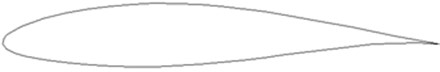
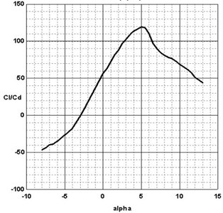
NACA63 series is the most widely used airfoil, which is a high lift airfoil influenced little by the surface roughness. This paper chooses NACA63-412 airfoil, which is shown in Fig. 1. Its maximum camber is 15 % which is in the 35.1 % airfoil. Its maximum surface in 50 % airfoil is 2.21 %. According to the data in the Table 1, 106 is chosen for the Reynolds number. With the software Profili, the relationship between lift drag ratio and angle of attack is obtained as shown in Fig. 2. Obviously, when attack angle is 5 degrees, the lift drag ratio reached the maximum. So 5 degree is chosen for the blade attack angle.
Fig. 1Airfoil NACA63-412
The blade is divided into 21 sections along the length direction. According to Schmitz design model [8], the chord line and twist can be calculated:
where, is the number of leaves, is the lift coefficient of the leaf, is the distance that section to the leaf, is radius of blade, is the tip speed ratio, is blade attack angle.
Fig. 2The lift to drag ratio change chart of NACA63-412
Put the blade design parameters into the Eqs. (1) and (2), and get the blade chord length and twist, the results are shown in Fig. 3 and Fig. 4.
Fig. 3The chord length varies with the radius
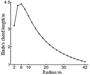
Fig. 4The blade torsional angle varies with the radius
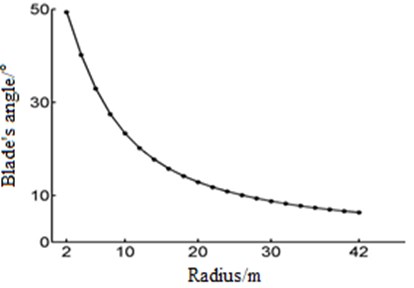
From the diagram, the maximum chord length of blade is in the section of the radius 6 m, and the maximum value is 4.4 m. And after the radius 6 m, Chord length decreases with the increase of radius. Blade twist decreases with radius increasing, the maximum value is 49 degrees.
2.2. Three dimensional modeling of blade
The coordinate transformation is conducted by each cross profile data exported from Pofili, and the cross profile coordinate of the importing 3D software blade can be obtained. The steps are as follows [12]:
1) Airfoil data is obtained by Profili software (, ).
2) Take the aerodynamic center as the origin (, ), and let the leading edge and trailing edge connection as the axis (, ). Then:
3) Combining with the chord length the airfoil coordinates are calculated:
where – chord length.
4) Solve the three-dimensional coordinate (, , ):
The actual coordinates (, , ) of each section of the blade can be obtained through the above steps. Data is imported into Solidworks software, and the 21 airfoil section curve is generated, as shown in Fig. 5.
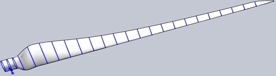
Set the curves as the combined curve, based on the section. Then connect the various curves by curve lofting. At last, 3D graphics blade is obtained, as shown in Fig. 6.
Fig. 5The curve of each section element of the blade
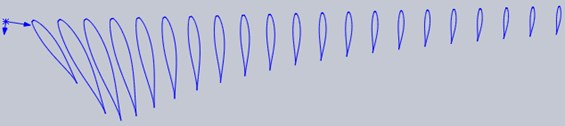
Fig. 6Three dimensional graphics of the blade
3. Modal analysis
The 3D model is imported into Ansys software. With the method of meshing blades by adaptive division, the blades is divided into 42478 units, the number of nodes is 43500, and blade grid graph is shown in Fig. 7.
The material glass steel is chosen for blade, and material properties are shown in Table 2.
Fig. 7Grid graph of the blade
a) Integral blade grid graph
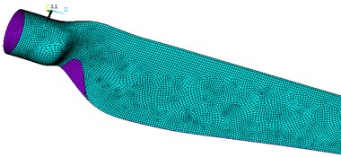
b) Local blade grid graph
It is assumed that considering the wind turbine at rated speed is 19 rad/min, different thickness of blade are set with respectively the thickness of each layer 0.2 mm, 0.4 mm, 0.6 mm, 0.8 mm and 1 mm, which is a total of 10 layer. Blade’s natural frequency curve is shown in Fig. 8.
Table 2Material properties of blade
(GPa) | (GPa) | (GPa) | (kg/m3) | |
62.5 | 16.5 | 5.5 | 0.2 | 1.7 |
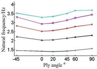
Fig. 8Natural frequencies of the blade under different layer thickness and ply angle
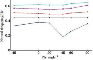
a) The first-order natural frequency
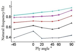
b) The second-order natural frequency
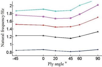
c) The third-order natural frequency
d) The fourth-order natural frequency
e) The fifth-order natural frequency
f) The sixth-order natural frequency
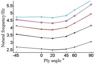
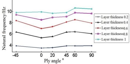
The Fig. 8 shows that with the single layer thickness increasing the natural frequency of each order of the blade is increasing under the circumstances of the same ply angle.
But when the single layer thickness is 0.2 mm, blade’s frequency have large amplitude of variation in the first order and second order. When single layer thickness is 0.9 mm, the sixth order frequency will rise in the –45°-0°, contrary to the change of frequency of other layer thickness.
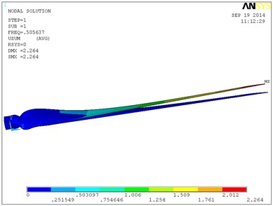
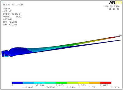
Fig. 9 shows a vibration modal of the blade’s first six orders in which the single layer thickness is 0.6 mm, and ply angle is 60°. The blade is mainly waving vibration in the first order, second order and third order modes. That is to say blade is in the bending vibration in the plane of perpendicular to the rotation direction. From the fourth order modal blade began to swing vibration, and with the increasing of order its torsion in certain angle is occurring. In the sixth modal blade torsion angle is relatively larger, and the maximum displacement in flap-wise direction is 3.41 m. With the increase of layer thickness, the natural frequency of the blade is increased, so the torsion angle of the blade of high order will increase. When the single layer thickness is 0.8 mm, the torsion angle of the blade high order will be greater. So the 0.6 mm layer thickness is selected, and the total thickness is 6 mm.
The Fig. 9 also shows that the natural frequency of blade varies with the change of the ply angle, but the changing trend of the blade’s natural frequency is irrelative with the layer thickness. So the layer thickness of 0.6 mm is taken as an example to analyze the influence of different ply angle on the natural frequency of the blades. The data is shown in Table 3.
Fig. 9Vibration modal of the blade
a) The firth-order modal
b) The second-order modal
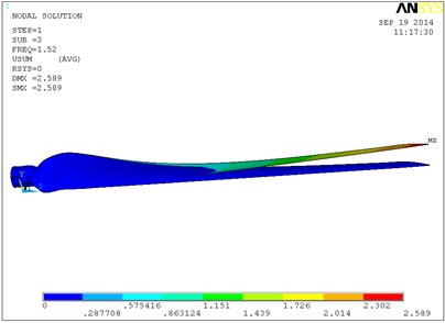
c) The third-order modal
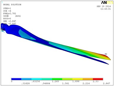
d) The fourth-order modal
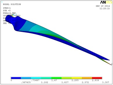
e) The fifth-order modal
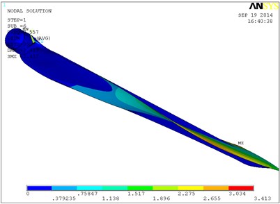
f) The sixth-order modal
Different forms of vibration will occur during the course of vibration, so the variation rule of each order natural frequency will not be the same. As Fig. 8 and Table 3 show it is not obvious that the first order natural frequency of the blade increase with angle change, which can be ignored. The second order frequency increase with the angle during –45°-0°and 60°-90°. The third order and fifth order frequency decrease with the angle in –45°-20°, and when angle is in 60°-90°, the frequency is increasing. The fourth order frequency deceases with the increase of angle in –45°-0°, while it increases with angle in 0°-90°. At last, the sixth order frequency decreases with ply angle when it is during –45°-0° and 60°-90°, and natural frequency increases at 0°-60°.
Table 3The natural frequencies of the blades
Ply angle (°) order | –45 | 0 | 20 | 45 | 60 | 90 |
1 | 0.508 | 0.5 | 0.49 | 0.49 | 0.505 | 0.52 |
2 | 0.69 | 0.72 | 0.71 | 0.71 | 0.73 | 0.82 |
3 | 1.52 | 1.5 | 1.45 | 1.46 | 1.51 | 1.7 |
4 | 2.82 | 2.52 | 2.56 | 2.68 | 2.78 | 2.9 |
5 | 4.13 | 3.9 | 3.86 | 4.02 | 4.31 | 4.94 |
6 | 8.38 | 6.96 | 7.3 | 8.14 | 8.55 | 7.94 |
Wind turbine blade requires a large stiffness in a condition of reducing the weight as much as possible, i.e. the higher the natural frequency is, the better it is. When the ply angle is 20°, 45° or 60°, the turning point of some order natural frequency of the blade is occurring. And when ply angle is 20°, blade’s third order and fifth order natural frequency is the minimum; and when the ply angle is 60°, the natural frequency reach the maximum. So it is most appropriate to choose the ply angle of 60°.
4. Aeroelastic analysis
Blade aerodynamic load analysis is an important step in designing and checking the wind turbine. It is the aerodynamic performance which determines how much wind energy can be transformed into electrical energy. The aerodynamic load functioning on the blade is the main source of power of wind turbine. The calculation of aerodynamic load is mainly based on the blade element momentum theory (BEM theory). The theory assumes the blade is in a steady uniform airflow and the influence factors are ignored such as blade pitch, yaw and cone angle, and the force is decomposed into the chord direction and perpendicular to the chord direction [12]. Assuming the concentrated loads on the blade length along and direction is and , then:
where: – the density of air, – the relative flow velocity, – blade section chord, – normal force coefficient, – tangential force coefficient.
Put the blade parameters into the type 6 and 7, and we can obtain concentrated load ( direction) varies with blade radius curve, as shown in Fig. 10.
Fig. 10Distribution of the aerodynamic loading in X direction
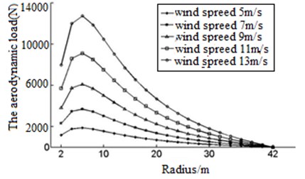
Fig. 10 shows as the blade chord length growth, blade aerodynamic concentrated load () in linear growth, and the largest load in the largest chord length, tip loading force can be seen as 0. Blade in the direction of axis load change rule with the same force.
Fig. 11The finite element mode of the blade
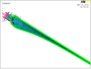
The load is applied on each section. Because each section is composed of many nodes, after the grid division, sometimes each part of the model is not continuous, so the connection can be established with free coupling.
The ply angle is selected as –45°, 0°, 20°, 45°, 60° and 90°, and by using the blade finite element mode, some curves can be obtained, as shown in Fig. 12 and Fig. 13.
Fig. 12The maximum concentration stress

Fig. 13The maximum displacement of the offset
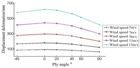
From the Fig. 12, we know the data has a same trend under any wind speed. Fig. 13 shows the concentrated stress drops during –45°-45°, but in 45°-90° interval, concentrated stress begins to rise. So the ply angle 45° is a turning point, maybe the blade’s stress is minimal when ply angle is in the 45° near. Therefore, taking the wind speed of 5 m/s as an example, the ply angle is set to 43°, 44°, 45°, and the analysis of the data is shown in Table 4.
We can see from Table 4, the maximum stress of blade is the smallest when the ply angle is 44°. So the ply angle we choose is 44°, when this time blade has the best aerodynamic loading characteristics.
Table 4The maximum stress and maximum displacement offset
Ply angle | 43° | 44° | 45° |
Maximum stress (MPa) | 762.87 | 622.4 | 623.3 |
Maximum displacement offset (mm) | 85.61 | 83.69 | 83.3 |
5. Conclusions
Considering the change of circumferential velocity in the actual process of air flow, the aerodynamic shape of a 2 MW wind turbine blade has been designed based on the Schmitz theory, and the solid model for the blade has been established. The influences of the layer thickness and ply angle on the modal characteristics and aerodynamic load of the blade have been analyzed. The results show that:
1) The maximum chord length of blade in the section radius is 6 m, and the maximum value is 4.4 m. After the radius of 6 m, chord length decreases with the increase of radius. Blade twist angle decreases with increasing radius, and the maximum value is 49 degrees.
2) With the increase of the composite blade single layer thickness, on the same ply angle, the natural frequencies increase. In single layer thickness is 0.6 mm, the blade has the best modal characteristics.
3) The natural frequency of the blade’s different order varies with ply angle, but whatever the layer thickness increase or decrease, its same order natural frequency has a same change trend. When the ply angle is 20°, 45° or 60°, the turning point of some order natural frequency of the blade is occurring. And when ply angle is 20°, blade’s third order and fifth order natural frequency is the minimum; and when the ply angle is 60°, the natural frequency reach the maximum. So it is most appropriate to choose the ply angle of 60°.
4) With the growth of the blade chord length, blade aerodynamic concentrated load is in linear growth, and the largest load is in the largest chord length; when ply angle is 44°, the maximum concentration stress on blade which has applied aerodynamic load is minimal.
References
-
Tenguria N., Mittal N. D. Modal analysis for blade of horizontal axis wind turbine. Asian Journal of Scientific Research, Vol. 4, Issue 4, 2011, p. 325-334.
-
Li Z. W., He D. X. Reviews of fluid dynamics researches in wind energy engineering. Advances in Mechanics, Vol. 43, Issue 5, 2013, p. 472-525.
-
Thomsen O. T. Sandwich materials for wind turbine blades: present and future. Journal of Sandwich Structures and Materials, Vol. 11, 2009, p. 6-26.
-
Jonkman J., Butterfield S. Definition of a 5-MW reference wind turbine for offshore system development. National Renewable Energy Laboratory, Vol. 12, 2009.
-
Yang H., Shen W. Z. Prediction of the wind turbine performance by using BEM with airfoil data extracted from CFD. Renewable Energy, Vol. 70, 2014, p. 106-115.
-
Zheng Y. Q., Zhao R. Z. Finite element modal analysis of large-scale composite wind turbine blade. Manufacturing Process and Equipment, Vol. 6, 2013, p. 453-457.
-
Cheng T. H. Fluid-structure coupled analyses of composite wind turbine blades. Advanced Materials Research, Vols. 25-28, 2007, p. 41-44.
-
Ali A., Horst W. A torque matched aerodynamic performance analysis method for the horizontal axis wind turbines. Wind Energy, Vol. 17, 2014, p. 1727-1736.
-
Chen C., Wang M. Modal analysis of wind turbine blades based on ANSYS modeling. Advanced Materials Research, Vol. 790, 2013, p. 655-658.
-
Kim T., Hansen A. Development of an anisotropic beam finite element for composite wind turbine blade in multibody system. Renewable Energy, Vol. 59, 2013, p. 172-183.
-
Martfnez Jaime, Bernabini Luca An improved BEM model for the power curve prediction of stall-regulated wind turbines. Wind Energy, Vol. 8, Issue 4, 2005, p. 385-302.
-
Dong O. Y., Oh J. K. Predicting wind turbine blade loads and aeroelastic response using a coupled CFD-CSD method. Renewable Energy, Vol. 11, 2014, p. 184-196.
-
Cheng O., Stephen T. Design, Manufacture and Testing of a Bend-Twist D-Spar. Sandia National Laboratory, Albuquerque, 1999.
About this article

This work was supported by the National Natural Science Foundation of China (11472103), and the Program for New Century Excellent Talents in University (NCET-13-0782).
