Abstract
A mathematical model is developed to study the shimmy oscillations of aircraft nose landing gear with a dual-wheel co-rotation configuration. This model incorporates the dynamics of the torsional and lateral mode and the non-linear kinematics of the tire. The procedure of different types of shimmy bifurcation analysis is described in detail. The effect of the co-rotation configuration on shimmy oscillation is compared with non-co-rotation wheels. More specifically, the wheel separation distance and wheel moment of inertia are selected as important parameters to study the effect of the co-rotation configuration on the aircraft shimmy. It is concluded that as the wheel separation distance increases, the lateral shimmy becomes more stable, while the torsional mode become less stable. In comparison to the non-co-rotation configuration, dual co-rotation wheels have a petty effect on landing gear with small wheel separations. However, in the condition of a relatively large distance between wheels, the co-rotation configuration has a great positive influence on the anti-torsional shimmy. The wheel moment inertia, within a practical range, affects shimmy oscillation weakly for both the co-rotation and the non-co-rotation configuration.
1. Introduction
One of the problems facing the aircraft community is landing gear dynamics, especially shimmy and brake-induced vibration [1]. Aircraft shimmy is one of the most widely known dynamic instability phenomena of the landing gears and has been studied intensively for more than 90 years. Shimmy is considered to be the self-induced swiveling of the nose landing gear (NLG) of an airplane during the taxiing process when launching or landing [2].
Shimmy may be caused by a number of conditions, such as low torsional stiffness, excessive free-play in the gear, wheel imbalance, or the presence of worn parts [1]. In consideration of airplane load, tire pressure, floating, and space for retractable landing gear, large and medium-sized aircrafts tend to use dual-wheel nose landing gear [3]. Once shimmy occurs during taxiing of an aircraft, the wheels turn right or left instead of moving forward, not in a straight line but in a curve on the runway. Accordingly, serpentine trace results.
In a curvilinear motion, the angular velocity of the dual wheels is not completely equal. In spite of this problem, many designers have elected to use a dual-wheel co-rotation nose landing gear to make sure that the velocity of the two wheels are the same in any given time [4, 5]. Thus the wheels can eliminate the unbalanced motion, and shimmy oscillation will be reduced or inhibited.
Landing gear shimmy is a non-linear problem of stability with vibration upon multiple DOFs. The dynamic system for the shimmy phenomenon includes many non-linear factors, such as varying tire models, structure clearance and coulomb friction [1]. To deal with such non-linear issues, a comprehensive control of relevant parameters along with the proper arrangement of non-linear factors can lead to bright prospects for bifurcation calculation theory [6-8]. Some software is available to deal with the bifurcation analysis of dynamics system conveniently, such as Matlab Matcont and AUTO. In this paper, Matlab Matcont is applied to deal with shimmy bifurcation analysis.
The paper is organized as follows. We first discuss the mathematical model of a dual-wheel co-rotation nose landing gear in Section 2. We then consider in Section 3 the procedure of shimmy bifurcation analysis, in which we show two-parameter bifurcation diagrams representing different types of dynamics in the plane of forward velocity of the aircraft and vertical force on the gear. Section 4 is devoted to the effect of the dual co-rotation wheels on shimmy reduction, with special emphasis on the parameter of the wheel-separation distance and the wheel moment of inertia. Finally, Section 5 summarizes the results of the investigation.
2. Shimmy mathematical model of a nose landing gear
The sketch of a typical dual-wheel co-rotation nose landing gear is shown in Fig. 1 [9]. It consists of a strut attached to the fuselage and an axle which supports a pair of wheels with flexible tires of radius . The fuselage moves at a forward velocity and exerts a vertical force on the NLG.
Fig. 1Schematic of an aircraft NLG with dual co-rotation wheels configuration
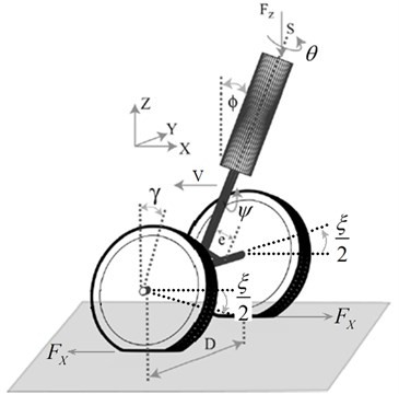
The strut is able to rotate about its axis , which generates the torsional mode . Due to a non-zero rake angle , the swivel angle is not equal to the rotation angle of the wheel , which is given by:
It also contributes to the effective caster length of the NLG given by:
where is the mechanical caster of length.
And the lateral bending mode of the strut is modeled by the angle of rotation about the axis . The two degrees of freedom are coupled via the lateral force caused by the lateral deformation of the tire. The wheel-ground interaction is modeled by the stretched string model [10]. The lateral deformation and slip angle are selected as the deformation parameter of the tire. Here, the slip angle , related to the lateral deformation and the relaxation length of the tire , is given by:
As is shown in Fig. 1, the wheels, fixed to the axle with a separation distance between their centers, are assumed to rotate at an equal angle reversely, where is the torsional angle of the axle. Besides, the difference of the forces on two wheels in is considered to be twice of . Apparently, on the effect of non-zero torsional angle of the strut, the overall vertical force on the NLG is asymmetrically divided into two forces and on the left and right wheels according to [9]:
Here, is the vertical stiffness of the tire, and which constitutes another geometric effect of a non-zero rake angle .
The overall model for the torsional and lateral vibration modes and their coupling through the elastic tires of both wheels then takes the form [9, 11]:
Eqs. (5) and (6) are for the torsional and lateral dynamics, and Eqs. (7) and (8) describe the non-linear kinematics of the tire deformation and of the left and right tires, respectively. Eq. (9) shows the relation between the longitude deformation and the longitude force on the contact point of the tire, regardless of longitude slip of the tire. Eq. (10) depicts the torsional dynamics of the wheel axle.
The terms and in Eq. (5) correspond to the moments generated due to the stiffness and damping of the strut in the torsional mode and are given by:
where is the torsional stiffness, is the linear damping.
The combined moment , which models the torsional tire interaction with the ground, is given by:
where is the self-aligning moment and is the restoring force of the tire.
The self-aligning moment is a function of the slip angle [12]:
where is the tire torsional stiffness, and is the limit slip angle. If current slip angle is beyond , then the self-aligning moment is taken to be zero.
The lateral restoring force due to tire deformation is described by the fitting curve based on experiment [13, 14]:
where is the tire lateral stiffness.
The moment due to the tread damping of the tire is given by:
where is the tire lateral damping coefficient.
The term is the gyroscopic moment of the wheel in the torsional mode and is given by:
where is the wheel moment of inertia.
Similarly, the terms and in Eq. (6) correspond to the moments generated due to the modal stiffness and damping in the lateral mode and are given by:
where is the lateral stiffness coefficient, and is the lateral damping coefficient.
The term in Eq. (6) is the result of the force created from the tire lateral deformation and is given by:
Also, is the gyroscopic moment of the wheel in the lateral mode and is given by:
Meanings and values of different parameters in the previous equations are listed in Table 1. The value is mainly referred to as A320 and C919 [9, 15]. For bifurcation continuation, some parameters are beyond the practical ranges.
Table 1Parameters and their values used in the model
Symbol | Parameter | Value | Unit |
Caster length | 0.12 | m | |
Rake angle | 0.1571 | rad | |
Gear height | 2.5 | m | |
Torsional stiffness of strut | 3.8×10⁵ | N·m/rad | |
Lateral stiffness of strut | 6.1×10⁶ | N·m/rad | |
Torsional stiffness of wheel axle | 2.0×10⁵ | N·m/rad | |
Torsional damping of strut | 300 | N·m·s/rad | |
Lateral damping of strut | 300 | N·m·s/rad | |
Torsional moment of inertia of strut | 100 | kg·m2 | |
Lateral moment of inertia of strut | 600 | kg·m2 | |
Distance between the wheels | 0.2 | m | |
Relaxation length | 0.3 | m | |
Contact path length | 0.2 | m | |
Radius of nose wheel | 0.362 | m | |
Self-aligning moment limit | 0.1745 | rad | |
Self-aligning coefficient of the tire | 1.0 | m/rad | |
Restoring coefficient of the tire | 0.002 | rad-1 | |
Vertical stiffness of the tire | 4.0×10⁶ | N/m | |
Longitude slip stiffness of the tire | 2.0×10⁵ | N/m | |
Damping coefficient of the tire | 285 | N·m2/rad | |
Wheel moment of inertia | 0.2 | kg·m2 | |
Vertical force on the gear | 0-750 | kN | |
Forward velocity | 0-200 | m/s |
3. Shimmy bifurcation analysis procedure
In the analysis of shimmy, it is of great importance to analyze the stability when landing gear strut has no torsional and bending deformation, tire contact centerline has no lateral displacement. Shimmy phenomenon takes place in the wake of Hopf bifurcation.
This section is aiming at the dual-wheel co-rotation landing gear shimmy model considering strut torsional and lateral bending deformation. With a vertical load of 200 kN and taxiing speed as the only control parameter, all the eigenvalues of the equilibrium under different taxiing velocity are calculated. On condition that the eigenvalues of Jacobi matrix , ,…, accord with , the equilibrium is thus stable. As control parameter α alters consecutively, all the eigenvalues changes as well. If a pair of eigenvalues satisfy when control parameter reaches a certain value , yet Hopf bifurcation occurs. In this case, control parameter is the bifurcation point for the original equilibrium. Afterwards, original equilibrium breaks apart and limit cycle oscillation with a constant amplitude occurs.
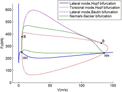
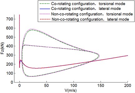
Based on the fact that Hopf bifurcation point is already acquired, landing gear vertical load is added as a second control parameter, then the shimmy equation within the V-Fz plane is solved to attain a new Hopf bifurcation diagram as is shown in Fig. 2. The bifurcation figure is comprised of two curves. The closed curve represents the torsional bifurcation, within which torsional shimmy happens. The other curve indicates lateral shimmy phenomenon. In the upper right of the curve should lateral bending shimmy takes place. These two curves intersect in two double-Hopf bifurcation points, labeled HH in the Fig. 2.
Within the variation of parameters, the lateral shimmy bifurcation stays stable, meanwhile the torsional shimmy turns dramatically. At point (5.149, 377.2) and (131.4, 326.0), the Bautin bifurcation happens as the marker ‘B’ indicates. Two Bautin bifurcation points divide the curve into two parts. The Hopf bifurcation of lower part is stable while that of upper part is not. So they no longer indicate the shimmy boundary. The original sole limit circle splits into two limit circles whose stability are opposite. In the two-parameter plane, the Bautin bifurcation theory is used to acquire the stable limit circle bifurcation prolong the unstable Hopf bifurcation.
Fig. 2Two-parameter control Hopf bifurcation diagram in V-Fz plane
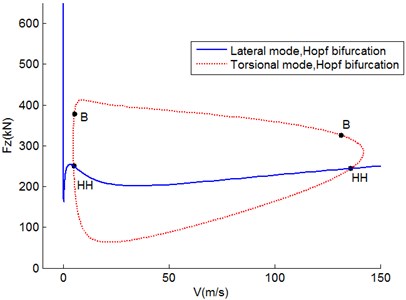
Fig. 3Bautin bifurcation diagram in V-Fz plane
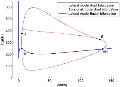
Fig. 4Two-parameter shimmy stability diagram in V-Fz plane
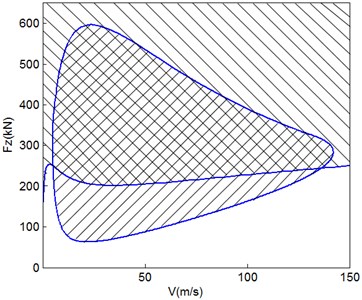
Fig. 5Neimark-Sacker bifurcation diagram
Based on the solutions above, Bautin bifurcation can be calculated as Fig. 3 depicted which is outside of the torsional Hopf bifurcation curve. As a result, due to the instability of Hopf bifurcation, the torsional shimmy region expands. Moreover, Bautin bifurcation curve is tangent to the Hopf bifurcation curve at the Bautin bifurcation point.
So far the shimmy stability diagram in the two-parameter plane is accomplished. Trim off the region of subcritical Hopf bifurcation and the final shimmy region figure comes forth as Fig. 4 displays. The right-slanted region surrounded by closed curves represents torsional shimmy oscillations. The top-right corner of the other curve which is left-slanted indicates lateral shimmy phenomenon. The region outside of the torsional and lateral shimmy region is the shimmy-free in the current two-parameter plane. Landing gear will encounter shimmy issue outside of the shimmy-free region.
It is noted that when shimmy phenomenon happens in the intersection of torsional and lateral shimmy areas, unneutral equilibrium state is not certain to tell there exists stable torsional and lateral shimmy oscillation with constant amplitude. Under certain circumstances, long time multi-periodic or quasi-periodic oscillation emerges [16]. Such phenomenon results from oscillation coupling of different frequencies. Based on the Poincaré normal form for dynamic equations, Neimark-Sacker bifurcation showing torsional and lateral shimmy is calculated as Fig. 5 shows.
It is indicated that near Neimark-Sacker bifurcation, multi-periodic or quasi-periodic shimmy is likely to take place. However, the Neimark-Sacker bifurcation of aircraft shimmy is subcritical, which means the multi-periodic or quasi-periodic phenomena are merely temporary [6]. As a result, temporary quasi-periodic phenomena take place during the interim of landing gear shimmy, yet periodic oscillation still plays a dominant role in the end. Therefore, such interim will be neglected in this paper.
4. The effect of co-rotation configuration on shimmy oscillations.
We consider the bifurcation diagram in the Fz-V plane to provide a global view of the overall dynamics. Specifically, comparisons between co-rotation configuration and non-co-rotation configuration are made to determine the influence of co-rotation configuration on shimmy oscillation in terms of different wheel-separation distance and moment of inertia of the wheels, respectively.
4.1. Effect of separation distance on shimmy oscillations
The distance between the wheels is a prominent parameter of a co-rotation dual-wheel landing gear shimmy model. This distance contributes to the difference of the wheel load while working, as well as the difference in contact force and moment between the wheel and the ground, which brings a huge impact on the torsional and bending degrees of freedom of the strut. In an attempt to study the influence of distance between the wheels on aircraft shimmy, the shimmy diagram for co-rotation configuration while 0.1 m, 0.2 m, 0.3 m are calculated respectively.
Fig. 6Two-parameter stability diagram in Fz-V plane for D= 0.1 m
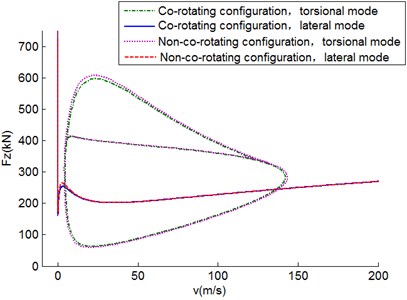
Fig. 7Two-parameter stability diagram in Fz-V plane for D= 0.2 m
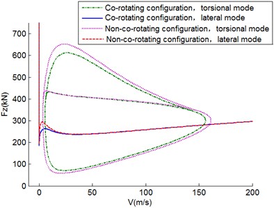
Figs. 6-8 show the shimmy regions under different distances between wheels of co-rotation configuration. As the distance gets larger, the torsional shimmy region tends to expand while the lateral shimmy region squeezes. The larger distance grants a higher bending stiffness of the strut, which hinders lateral shimmy and boosts torsional shimmy. The stability of the region within the low and mid-low velocity remains the same as shimmy region expands towards the high speed and high vertical load when the distance increases. Lateral shimmy region expands along the direction of high vertical load. An even larger distance might lead to a complex bifurcation phenomenon [9]. Taking a normal range of distance into consideration, parameter analysis of extreme distance between wheels will not be performed in this paper. The same rule can be easily identified in the non-co-rotation configuration.
For comparison, the shimmy diagrams under the same distance in the co-rotation and non-co-rotation configuration are calculated. When 0.1 m, the shimmy region of non-co-rotation wheels is almost the same as that of the co-rotation, and the co-rotation configuration affects shimmy phenomenon weakly. When the distance reaches 0.2 m, the torsional shimmy region for the co-rotation wheels is evidently smaller. As for the lateral shimmy region, co-rotation configuration is only a bit bigger under a low velocity and low vertical load. When the distance gets to 0.3 m, the shimmy region for the co-rotation wheels shrinks further to its center. Torsional shimmy does not take place along the edge of the torsional shimmy region for the non-co-rotation configuration. Yet the lateral shimmy region is not significantly altered.
Fig. 8Two-parameter stability diagram in Fz-V plane for D= 0.3 m
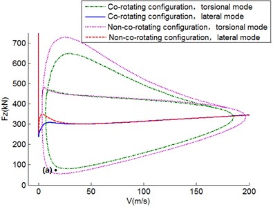
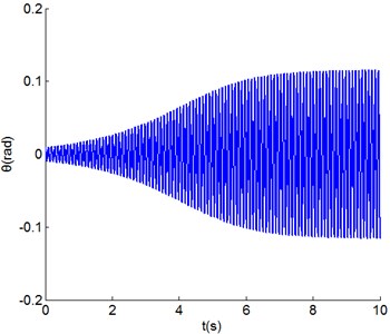
Figs. 9-10 show an example of torsional shimmy oscillations, specifically for 20 m/s and 75 kN, which corresponds to the labelled point (a) in Fig. 8. The shimmy dynamics Eqs. (5)-(10) are calculated in time domain with the fourth-order Runge-Kutta method.
As Fig. 8 shows, this typical point ( 20 m/s and 75 kN) is in the torsional shimmy region of the non-co-rotation wheels and out of the torsional shimmy region of the co-rotation configuration. It is demonstrated by graphs in time domain shown in Figs. 9-10. Although the same initial condition ( 0.01 rad) is applied, the torsional angle of co-rotation configuration decreases quickly. However, it is clear that torsional shimmy oscillation of non-co-rotation configuration happens because the torsional angle increases to almost 0.1 rad in 10 s.
Fig. 9Time series of the torsional angle of co-rotation configuration
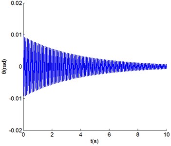
Fig. 10Time series of the torsional angle of non-co-rotation configuration
In Eq. (6), the effects of the co-rotation configuration on strut torsional stiffness are condensed into the last term, which is the restoring moment resulting from vertical load difference. The wheel-separation distance poses as the moment arm, hence the distance between wheels has a strong connection with co-rotation configuration.
4.2. Effect of moment of inertia on shimmy oscillations
Commercial aircrafts usually have NLGs with large wheels, heavy tires and a considerable moment of inertia of the wheels. Hence, moment of inertia of the wheels is the other parameter of particular significance in the determination of the influence of co-rotation configuration on shimmy oscillation. In order to investigate the influence of the moment of inertia of the wheels on aircraft shimmy, we increase at 0.3 kg∙m2, 0.8 kg∙m2, 1.1 kg∙m2 while setting the wheel-separation distance constant at 0.1 m.
Figs. 11-13 depict the two-parameter stability diagrams of shimmy oscillation under circumstances of different moments of inertia. For the co-rotation configuration, the regions of both torsional mode and lateral mode remain almost constant as the moment of inertia increases. Therefore, the effect of wheel moment of inertia on the dual-wheel co-rotation landing gear is quite limited. On the other hand, the torsional shimmy regions of the co-rotation wheels is only a bit smaller than that of non-co-rotation wheels under low velocity and a large vertical force, while in other parts of the diagram, the two curves coincide with each other. As for lateral shimmy, these different configurations show no difference in various wheel moments of inertia.
Fig. 11Two-parameter stability diagram in Fz-V plane for I= 0.3 kg∙m2
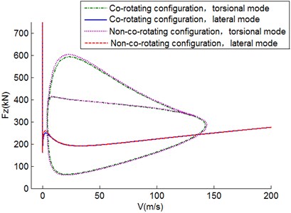
Fig. 12Two-parameter stability diagram in Fz-V plane for I= 0.8 kg∙m2
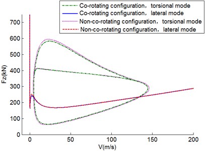
Fig. 13Two-parameter stability diagram in Fz-V plane for I= 1.1 kg∙m2
5. Conclusions
In this paper, applied bifurcation theory in the shimmy analysis of dual co-rotation wheels was studied through a nonlinear model. The procedure to determine the shimmy region of lateral mode and torsional mode is discussed in detail. The wheel separation distance and wheel moment of inertia are selected as important parameters to study the effect of co-rotation configuration on aircraft shimmy. The work of this paper demonstrates that:
1) Increasing the wheel separation distance is equivalent to enlarging the lateral stiffness of the strut, which contributes to enlarging regions of torsional shimmy and reducing the areas of lateral shimmy.
2) In comparison to the non-co-rotation configuration, dual co-rotation wheels have a petty effect on landing gears with small wheel separations. However, in the condition of a relatively large distance between wheels, co-rotation configuration has a great positive influence on anti-torsional shimmy.
3) The wheel moment inertia, within a practical range, affects shimmy oscillation weakly for both the co-rotation and the non-co-rotation configuration.
The conclusions are helpful in designing the NLG of a shimmy-free aircraft. It is suggested that a well-chosen moderately large separation distance between the wheels, relative to the lateral stiffness of the strut, helps to minimize or even eliminate shimmy oscillation in both lateral mode and torsional mode. Co-rotation configuration has a significant advantage when the wheel separation distance is large enough.
References
-
Pritchard Jocelyn I. An Overview of Landing Gear Dynamics. NASA/TM, 1999.
-
Moreland J. W. The story of shimmy. Journal of the Aeronautical Sciences, Vol. 21, Issue 12, 1954, p. 793-808.
-
Norman S. Aircraft Landing Gear design: Principles and Practices. American Institute of Aeronautics and Astronautics, Washington, D.C., 1998.
-
Stevens J. E. Shimmy of a nose gear with dual co-rotation wheels. Journal of the Aerospace Sciences, Vol. 28, Issue 8, 1961, p. 622-630.
-
Beery R. W. Mathematical analysis of co-rotation nose-gear shimmy phenomenon. Journal of the Aerospace Sciences, Vol. 29, Issue 12, 1962, p. 1462-1470.
-
Thota Phanikrishna, Krauskopf Bernd, Lowenberg Mark Bifurcation analysis of nose-landing-gear shimmy with lateral and longitudinal bending. Journal of Aircraft, Vol. 47, Issue 1, 2010, p. 87-95.
-
He Lijuan, Zhou Yucun Analysis of Hopf bifurcation of steering wheel shimmy of automobile. Applied Mechanics and Materials, Vol. 344, 2013, p. 61-65.
-
Kuznetsov Y. A. Elements of Applied Bifurcation Theory, Second Edition, Springer-Verlag, New York, 1997.
-
Thota Phanikrishna, Krauskopf Bernd, Lowenberg Mark Multi-parameter bifurcation study of shimmy oscillations in a dual-wheel aircraft nose landing gear. Nonlinear Dynamics, Vol. 70, Issue 2, 2012, p. 1675-1688.
-
von Schlippe B., Dietrich R. Shimmying of a Pneumatic Wheel. NACA TM-1365, 1947.
-
Wang Xuejun Stability Analysis of Aircraft Nose Landing Gear Shimmy. Nanjing University of Aeronautics and Astronautics, Nanjing, 1991.
-
Somieski G. Shimmy analysis of a simple aircraft nose landing gear model using different mathematical methods. Aerospace Science and Technology, Vol. 1, Issue 8, 1997, p. 545-555.
-
Thota Phanikrishna, Krauskopf Bernd, Lowenberg Mark Interaction of torsion and lateral bending in aircraft nose landing gear shimmy. Nonlinear Dynamics, Vol. 57, Issue 3, 2008, p. 455-467.
-
Thota Phanikrishna, Krauskopf Bernd, Lowenberg Mark Influence of tire inflation pressure on nose landing gear shimmy. Journal of Aircraft, Vol. 47, Issue 5, 2010, p. 1697-1706.
-
Fei Feng, Hong Nie, Ming Zhang, Yiming Peng Effect of torsional damping on aircraft nose landing-gear shimmy. Journal of Aircraft, 2014, p. 1-8.
-
Stepan G. Chaotic motion of wheels. Vehicle System Dynamics, Vol. 20, Issue 6, 1991, p. 341-351.
About this article

We thank Ran Xu and Guangfei Duan for their helpful comments and writing skills.
