Abstract
A novel piezoelectric balance was developed to measure the six-component forces for the complex aircraft scaled model in the impulse combustion wind tunnel at a short duration airloads Mach number of 5. The piezoelectric balance using four triaxial piezoelectric load cells yields the high stiffness, sensitive and good dynamic response characteristics. The dynamic model-balance system was built to analyze the vibration characteristic. The time series analysis approach was developed on the basis of the system transfer function and the natural frequency, and the accelerated forces which induce the airloads overshooting oscillations had been obtained by the second order derivatives function. The experimental results have shown that the problem of overshooting oscillations effect of the impulse can be effectively solved by the acceleration compensation technology for the complex test model with the novel piezoelectric balance.
1. Introduction
This paper presents the results of an internal research effort to develop and validate novel acceleration solution method for the multi-component aerodynamic forces on the simulation aircraft device in the impulse wind tunnel. On the basis of previous works, a novel six-component piezoelectric wind tunnel balance had been developed to measure the aerodynamic forces and moments of a mechanical device [1, 2]. The device motion can be accurately controlled. The piezoelectric wind tunnel balance had been accomplished the static and dynamic calibration on the experimental platform [3]. The piezoelectric balance is high stiffness, high frequency response, high sensitivity and wide measuring range. The prominent advantage over the conventional strain gage balance is the good performance of dynamic response characteristics. The experimental results in the transonic wind tunnel have displayed that the dynamic airloads can be effectively measured by the piezoelectric balance.
However, unlike conventional transonic wind tunnel test, the sudden impact from the aerodynamic forces usually generates oscillations of the aircraft device. Therefore, for the short duration impact measurement, typically within 300ms, offers no opportunity to completely damp the oscillations during the steady flow. This makes direct force measurements challenging as the inertial forces resulting from the model and piezoelectric balance accelerations add to the aerodynamic forces and must therefore be accounted for to obtain accurate force and moment measurements.
In the past, various techniques have been developed to overcome these problems. Dibesh D. Joshi utilized an external balance for the drag measurement in a hypersonic shock tunnel. An accelerometer was placed on the model-balance structure to compensate the inertial forces [4]. Michael G. Werling used a conventional five-component strain gauge balance to measure the wingtip force at Mach 0.75, and a dynamic calibration was applied to the force balance to account for the sudden aerodynamic loading [5]. Experiments to measure the forces and moments acting on a blunt-cone capsule model were carried out by Stuart J. Laurence. A combined accelerometers and visualization-based tracking technique was proposed to measure the short duration impulse [6]. In the meanwhile, dynamic calibration methods of wind tunnel balances for short duration impulse measurement had been researched [7]. Mee D. J. analyzed different techniques for the calibration of force balances for use in short-duration impulse hypersonic facilities. The impulse force hammer was used to apply and measure the force pulse [8]. Two force balance techniques for use in hypersonic impulse facilities were compared by measuring the drag force by Niranjan Sahoo. And the impulse response function was determined using the cut-weight method [9]. Recent measurements by Marineau have shown that it is possible to make accurate force measurements in shock tunnels with an acceleration compensated strain gage force balance [10]. The results were compared with a new six-component acceleration compensated piezoelectric balance under the same nominal flow conditions on the exact same aerodynamic model. The new piezoelectric balance has both frequency response and sensitivity increased by a factor of approximately four compared to the strain gage force balance [11].
Over the years, the strain gage force balance was designed as a thin-walled structure so that it was liable to deformation by external force. In addition, the structure of the aircraft model is simple, and the natural frequency of the model-balance system is therefore available for the short duration measurement. However, for the purpose of complex model-balance system and hypersonic wind tunnel environment airloads measurement, a higher stiffness and better dynamic characteristics of balance should be designed. In this case, a novel piezoelectric balance and the model system endeavor to be developed. The primary objective of this paper is therefore to demonstrate the validity of the complex model-balance measuring method in the impulse combustion wind tunnel.
The normal force was obtained with the piezoelectric balance at Mach 5. For the purpose of overcoming the overshooting oscillations signal during the transient impact, an accelerated forces compensation method on the basis of the time series analysis approach has been developed for the dynamic short duration measurement in this paper.
2. Theory and method
In recent years, the dynamic multi-component forces measurement plays an important role in research aerodynamics test, modal analysis, crash testing and so on. In these cases, the static calibration results are no longer appropriate for the dynamic measurement. Especially, for the high accuracy multi-component measurement results required, it is major different that short duration impact generates the oscillations effect comparing with the traditional steady flow.
2.1. Structure of the model device
[1] has introduced the design of the aircraft device. This mechanical device is to simulate the hatch open motion. Then it is developed to research the aerodynamic characteristics of the multi-component airloads which change with the hatch open angle within 0-120°. The whole system includes two parts, one is the hatch open motion device, and the other is the six-component piezoelectric balance, the whole system which is designed as a ship shell cabin structure is shown in Fig. 1(a). The hatch’s open angle is 0°. The direct assembly parts joined with the piezoelectric balance are the support frame, hatch and plug. The local assembly device is shown in Fig. 1(b).
As the material of quartz is stiff, the piezoelectric sensors have considerable advantages comparing with other sensors used to measure the impact airloads. The triaxial piezoelectric load cells are very compact, rigid and therefore have a high natural frequency which allows precise measurement of highly dynamic circumstances. It can be seen as the non-displacement type sensors. The four triaxial piezoelectric load cells are arranged as a rectangle mode. Each load cells are preloaded with a bolt which makes the piezoelectric balance connecting to the support frame closely. There is a self-lubricating gasket between the shaft and support. Therefore, there is no displacement of direction when the airloads act on the hatch.
Fig. 1Schematic diagram of the model-balance system
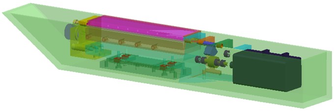
a) The whole aerodynamic model
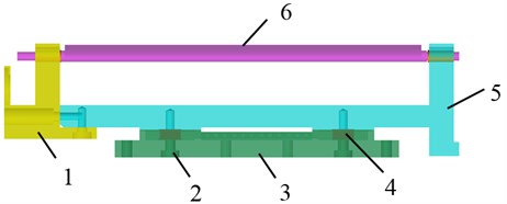
b) The balance measurement model: 1 – plug, 2 – preload bolt, 3 – piezoelectric balance, 4 – triaxial sensor, 5 – support frame, 6 – hatch
2.2. Model of the dynamic system
The dynamic motion system on the basis of the piezoelectric balance can be described by an equivalent model, as is shown in Fig. 2.
Fig. 2Equivalent model of the motion system
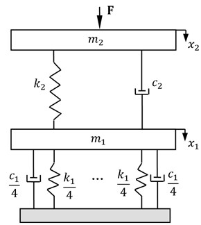
As it cannot be assumed that the four preloaded bolts are infinitely stiff, it is described by approximation as the bolts stiffness with damping coefficient . The aircraft model, which is a combination of support, plug and hatch, has the stiffness and the damping coefficient . Meanwhile, the effective mass acting on the piezoelectric balance is composed of the masses of the connecting elements. The mass covers the mass of the four triaxial piezoelectric load cells. Take the downward direction for example, the exciting force is the impact of the airloads, and the displacements of the masses from the rest positions are denoted by .
The vibration model is therefore described by the following system of differential equations:
For the high rigid connection components of the aircraft model, when the external impact force act, compared with the stiffness, the system damping is in general low and then it can be neglected for the moment. Therefore, the Eq. (1) can be expressed by the following relation:
Due to the impact force acting on the model system which generates the oscillations instantaneously, the system itself therefore generates the acceleration. Though the effect of acceleration can be neglected for the steady flow and long duration measurement, the last smooth section of the data can represent the actual airloads. However, for the short duration impact force measurement in the impulse wind tunnel, the experimental model has no opportunity to completely damp the oscillations during the steady flow when the airloads stop. Therefore, the inertial forces generated by the accelerated masses should be taken into consideration. The second polynomial of Eq. (2) displays the derived inertial forces in theory, which adds to the aerodynamic forces as the errors. And the first polynomial displays the spring forces of the piezoelectric balance which is the measuring results.
2.3. Time series analysis approach
The inertial force can be determined from the accelerations of the effective dynamic mass. The accelerations related to the dynamic forces can be seen the so-called accelerated forces , which can be written in theory as follows:
where is the density of the mass distribution. The variable displacements will change with time . Therefore, the accelerated forces consists of a series of displacements changing with time.
In addition, on the basis of Eq. (2), the impact force can be expressed as:
Due to the stiffness of the model and piezoelectric balance system, the dynamic behavior of the system can be modeled as time-invariant, causal and linear with an output which is the resulting piezoelectric balance signal, being related to the applied impact force , where is the unit impulse function, is the true impulse response scaled in magnitude by , via an impulse response function , then the relationship between the input and output as described by the convolution integral:
The impulse response function can be solved by the dynamic calibration. Then time series of the applied impact force can be obtained by the deconvolution method.
According to Eq. (2) and Eq. (4), the second order differential of can be concluded by the following equation:
As the masses of the triaxial piezoelectric load cells are much less than the model device, the so-called accelerated forces can be expressed by the direct contact support frame approximately:
And then, to combine the Eq. (6) with Eq. (7), the accelerated forces can be further expressed as:
where is the natural frequency of the model system. Therefore, the accelerated forces can be obtained by deconvolution the time series of the measuring airloads with the second order derivatives function. More precisely, the accelerated forces of the system are closely related to the second order differential of piezoelectric balance measurement results and the natural frequency of the model system.
3. Dynamic calibration
3.1. Modal analysis of the system
For the purpose of the impulse response function solution, the frequency domain modal analysis method is adopted [12]. The mass-spring-damping system of the aircraft model and the piezoelectric balance can be seen a single-input single-output transient dynamic response system, and the vibration equation can be written as follows:
then can be expressed as:
where and are the 2×2 matrix, the state vector is given as:
when the system is in the case of free vibration, supposing that 0, then the particular solution can be obtained:
The characteristic equation of the system is as follows:
and then parts conjugate eigenvalues , and eigenvectors , are in the Eq. (13) respectively. Which are given as:
then the eigenvectors matrix can be expressed as:
where , . is the modal matrix according to the state vector , and can be transformed by the complex modal coordinates .
Therefore, the Eq. (9) can be decoupled by the following equation:
The Fourier transform of the Eq. (16) can be obtained:
In the physics coordinate, the impulse response function of the single-input single-output transient dynamic complex modal system can be expressed as:
3.2. Nonlinear parameters identification
For the purpose of acquisition an accurate impulse response function, the nonlinear identification method is adopted. The errors matrix consists of an experimental frequency response function and the theoretical impulse response function is therefore used to fit the impulse response function. The relationship between the errors matrix and the identified modal parameters is nonlinear.
As is shown in the Eq. (18), the Laplace transformation of both sides of equal sign can be expressed as:
where and are the residues of at the poles of complex modal frequency and respectively. Which are given as:
then the Eq. (19) is equivalent to:
Therefore, the modal parameters, such as the real and imaginary parts of the poles and residues, are needed to be identified are shown in the Eq. (21). Due to the dynamic system of the mode number is , the number of the parameters is 4, which can be expressed as:
3.3. Least-square curve fit
As is shown, the vector matrix consist of all the modal parameters, on the basis of the every modal frequency , the errors matrix can be obtained:
where the measuring frequency points are , is the theoretical value of the frequency response function, and is the experimental values. For the frequency response function, the parameters identified are subjected to a least-square curve-fit on the basis of square errors, as is shown in the Eq. (23):
When takes the minimum value, the corresponding natural frequency and damping ratio are the best estimate values. Due to the frequency response function is a nonlinear combination based on the natural frequency and the damping ratio, the linear terms can be obtained with Taylor series expansion. Moreover, partial derivatives method is applied, and then the error function can be expressed as:
The Eq. (22) can be written as:
where is the initial iteration matrix, whose element is:
According to the Eq. (23) and Eq. (25), a derivative of the vector is solved and can be expressed as:
where the superscript represents conjugate transpose. When , the vector can be obtained:
Therefore, is the step of the cyclic iteration. Due to the experimental frequency response function can be acquired, the initial value of the iteration can be directly determined. Moreover, the theoretical impulse response function of the aircraft model and piezoelectric balance system can be concluded.
4. Experimental setup
4.1. Impulse excitation response experiment
For the purpose of acquiring the frequency response curve, an impulse excitation test is carried out on the platform. In this test, the outermost ship shell cabin structure is removed so that the bottom of the piezoelectric balance can be directly assembled on the test platform through several studs. The test platform is vibration isolated. The open angle of the hatch is 0°. The arrangement of the model and piezoelectric balance is shown in Fig. 3. A hammer equipped with a steel tip is used to apply and measure the force pulse.
Fig. 3Impulse excitation response experiment: 1 – force hammer, 2 – hatch, 3 – support frame, 4 – piezoelectric balance, 5 – plug, 6 – test platform
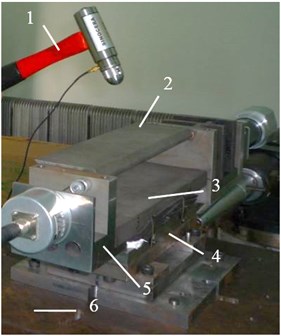
In order to simulate the sudden impact airloads in the impulse wind tunnel, the force exciting duration should be short enough. The input signal of the hammer and the output signal of the piezoelectric balance are acquired simultaneously. The output signal of the piezoelectric balance is transformed by FFT, and the frequency domain curve of the dynamic impulse response is obtained, which is shown in Fig. 4.
As can be seen from Fig. 4, three major peak points of the curve are appeared, and then the mode of this direction is therefore three orders. Furthermore, the natural frequency of the model and the balance system is 161.13 Hz. For the purpose of increasing the mechanical vibration frequency, the high stiffness piezoelectric balance is developed. The influences of rigid connections between the aircraft model and balance have been considered as well. The experimental results can fully meet the requirements for impulse wind tunnel test.
4.2. Impulse response function
According to the frequency response curve, the modal frequency can be directly obtained. Through the linear interpolation for the half power points method, the damping can be appropriately estimated. Furthermore, the cyclic iteration times have been decreased by the determined damping ratio compared with nonlinear identification. The necessary modal parameters identified are shown in Table 1.
Table 1Modal information of every order of the system
Mode | 1 | 2 | 3 |
Frequency (Hz) | 161.13 | 317.38 | 395.51 |
Damping | 0.031 | 0.0083 | 0.014 |
Real part | 0.0578 | 0.0196 | 0.0012 |
Imaginary part | –0.0806 | –0.0079 | –0.0036 |
For the purpose of improving the identification precision, some other parameters of points such as the inflexions and valleys are adopted as well. Therefore, the theoretical impulse response function of the system according to Eq. (19) can be obtained as follow:
where ,
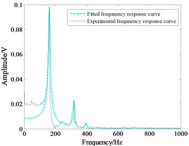
The comparison curve between the fitted impulse response and the experimental frequency response are shown in Fig. 5.
Therefore, the inverse Laplace transformation of the impulse response function can be obtained as the following equation, where the variable parameters are solved by previous work:
Fig. 4Amplitude-frequency response curve
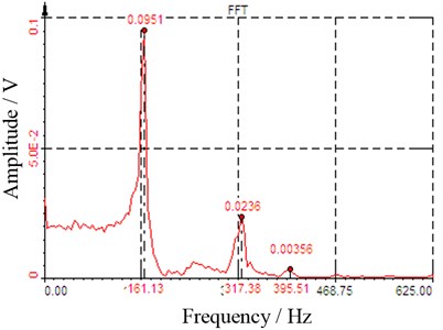
Fig. 5Comparison of the theoretical and the experimental frequency response
4.3. Wind tunnel test results
To validate the novel piezoelectric balance and the acceleration solution method, the test was accomplished in the Ø600 mm impulse combustion wind tunnel. The wind tunnel mainly consists of oxygen pipe, hydrogen pipe, quick-action value, spark plug, combustion chamber, conical nozzle, and test section. The combustion chamber is divided into two parts by an aluminum diaphragm. In the test, the mixed gas is ignited by the spark plug in the combustion chamber, and then the diaphragm is burst open simultaneously. The flows produced by the heater flow through the nozzle and are supplied to the test. Therefore, in the impulse combustion wind tunnel test, the transient impulse would act on the model-balance system instantaneously.
The Mach number was 5, the total pressure was 3.6 MPa, the total temperature was 1600 K, and the specific heat ratio of test gas was 1.28. The bottom of the model was fastened to the separate members in the test section and the angle of attack was 0°. The output data of the piezoelectric balance had been amplified by the charge amplifiers and then were acquired at 100 kHz using the Data Acquisition System providing 16 channels with 16 bit A/D conversion.
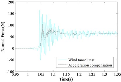
The piezoelectric balance test curve of the normal force is shown in Fig. 7 (the light-colored curve). Due to the transient impact of the airloads, the time domain waveform of the piezoelectric balance presents overshooting oscillations at the beginning moment 1.034 ms and continues the state until 1.126 ms, and then the oscillations decrease gradually. Good agreement for the theoretical analysis and experimental results that the accelerated forces of the model and piezoelectric balance system add to the aerodynamic forces.
The accelerated forces of the system can be obtained according to the Eq. (8), which is shown in Fig. 6. The normal force of the model with the accelerated forces compensation is shown in Fig. 7 (the dark curve). The experimental results were sampled at a high frequency due to the short duration impulse airloads. Therefore, the normal force signal was processed with the low pass filter to suppress the relatively high noise associated with the measurement system. As can be seen, the problem of overshooting oscillations effect of the impulse can be effectively solved.
Fig. 6Accelerated forces of the system
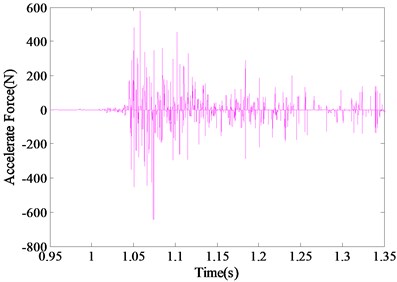
Fig. 7Comparison of the acceleration compensation curves
5. Conclusions
This research effort performed at an impulse combustion wind tunnel has shown that accurate impulse airloads can be measured by a novel piezoelectric balance without an additional accelerometer. This methodology using the time series analysis that the accelerated forces has been obtained by the second order derivatives function. The accelerated forces compensation method of the model system output yields the high stiffness, sensitive and good dynamic response characteristics. The theoretical analysis of the dynamic model has been built to describe the system response under the sudden impact. The results of the impact force are effectively demonstrated through comparison with directly measurement and with accelerated forces compensation. Therefore, the overshooting oscillations induced by the transient impulse can be solved and the accurate airloads measurements are obtained. The acceleration compensation technology processing the transient airloads measurement with piezoelectric balance will be used to build improved force balances for use in the wind tunnel, especially, for the purpose of measuring the short duration impulse aerodynamic force and moment.
References
-
Gao Y. F., Ren Z. J., Jia Z. Y., et al. A study on the dynamic six-component force measurement with wind loads. Proceedings of the Institution of Mechanical Engineers, Part C: Journal of Mechanical Engineering Science, Vol. 227, Issue 11, 2013, p. 2456-2466.
-
Jia Z. Y., Gao Y. F., Ren Z. J., et al. Research on the characteristics of a piezoelectric balance for the dynamic motion device. International Journal of Industrial and Systems Engineering, Vol. 18, Issue 3, 2014, p. 364-381.
-
Jia Z. Y., Gao Y. F., Ren Z. J., et al. Design and calibration method for a novel six-component piezoelectric balance. Proceedings of the Institution of Mechanical Engineers, Part C: Journal of Mechanical Engineering Science, Vol. 227, Issue 8, 2013, p. 1841-1852.
-
Dibesh D. J., Pravin V., Frank K. L. Acceleration compensation for drag measurements in hypersonic shock tunnel. 51st AIAA Aerospace Sciences Meeting including the New Horizons Forum and Aerospace Exposition, Grapevine, Texas, 2013, p. 1020.
-
Michael G. W., Jeiny E. G., Eric M. B., et al. Force measurements on a NACA 0012 wingtip at Mach 0.75. 51st AIAA Aerospace Sciences Meeting including the New Horizons Forum and Aerospace Exposition, Grapevine, Texas, 2013, p. 1026.
-
Stuart J. L., Jan M. S., Klaus H. Force and moment measurements on a free-flying capsule model in a high-enthalpy shock tunnel. 28th Aerodynamic Measurement Technology, Ground Testing, and Flight Testing Conference, New Orleans, Louisiana, 2012, p. 2861.
-
Robinson M. J., Schramm J. M., Hannemann K. Design and implementation of an internal stress force balance in a shock tunnel. CEAS Space Journal, Vol. 1, 2011, p. 45-57.
-
Mee D. J. Dynamic calibration of force balances for impulse hypersonic facilities. Shock Waves, Vol. 12, 2003, p. 443-455.
-
Sahoo N., Suryavamshi K., Reddy K. P. J., et al. Dynamic force balances for short-duration hypersonic testing facilities. Experiments in Fluids, Vol. 38, 2005, p. 606-614.
-
Marineau E., Maclean M., Mundy E. P., et al. Force measurements in hypervelocity flows with an acceleration-compensated strain-gauge balance. Journal of Spacecraft and Rockets, Vol. 49, Issue 3, 2012, p. 474-482.
-
Marineau E. Force measurements in hypervelocity flows with an acceleration compensated piezoelectric balance. 49th AIAA Aerospace Sciences Meeting, Orlando, Florida, 2011.
-
Bratland M., Haugen B., Rølvåg T. Modal analysis of active flexible multibody systems containing PID controllers with non-collocated sensors and actuators. Finite Elements in Analysis and Design, Vol. 91, 2014, p. 16-29.
About this article

This work was supported by the National Natural Science Foundation of China under Grant No. 51505299 and Liaoning Province Department of Education under Grant No. L2015384. The anonymous reviewers are sincerely appreciated for their valuable comments and suggestions to improve the paper.
