Abstract
Engine pylon is one of the most important components of large civil aircraft, playing an essential role in structure connecting and load bearing. It is chosen as the research target, and a full sized engine-pylon-wing finite element model is established. By conducting the simulations of different landing and impacting conditions, dynamical responses and separation status of the pylon are obtained. Some main factors that affect the pylon’s separation are found out on the basis of preliminary analysis. The reasonable pylon separations for belly landing with small pitch angles and dead-stick landing are achieved. At last, further measures to improve the modeling method and achieve better pylon separations are discussed based on a comparative analysis of all the simulation results. The proposed dynamical modeling method along with the emergency landing parameters and simulation results can provide certain reference to similar studies, pylon structure designs and validation tests.
1. Introduction
In the process of designing large civil aircraft, not only effective technical means should be applied to guarantee the smooth and reliable operation of aircraft, but also close attention should be paid to the occupant safety in emergency landing so as to improve the crashworthiness of the aircraft. Engine is the main source of the fires and explosions following plane crash. The technology of emergency breaking away between engine pylon and wing, as an effective measure to improve the aircraft safety, is of significance in reducing the possibility of secondary damage after a crash and striving for more chances to survive.
In the early 1980s, a plan called CID (Controlled Impact Demonstration) carried out by NASA and the Federal Aviation Administration. In1984, they conducted a landing impact test of the whole B720, and got the structural response data of a jumbo-jet in a crash for the first time [1, 2]. In addition, NASA conducted landing impact experiments with fuselage section of B737 three times during 1983 and 1986 [3-5]. Moreover, the Federal Aviation Administration took crash tests for the cabin of B737 twice in 1999 and 2000 respectively [6, 7].
Along with the sufficient accumulation of experimental data and the continuous improvement of collision theory, numerical analysis methods and computer technology, the crash simulation analysis of aircraft structure also developed rapidly. The United States established the corresponding model of simulation calculation during the CID project. According to the test data, the model and the analysis method are amended and optimized, and the final simulation result agreed well with the experimental value. In 1991, some of the data in the analysis report of Northwest Airlines Flight 255 crash accident given by D. E. Calkins, was obtained by simulation calculation, indicating that simulation analysis was applied in accident analysis at that time. Besides, in 2001, Karen E. Jackson and Edwin L. Fasanella did simulation calculation for the falling process of B737 fuselage, which carried dummy and luggage, with finite element software MSC. Dytran. After that, they got the acceleration response of structure under impact load, and the simulation result was in agreement with the test value [8, 9].
Since the 1990s, there have been more than 40 civil airplane accidents, including nearly 20 ones in which the engine pylon broke away from wing in the process of emergency landing, and engine pylon generally dropped far away from fuselage, and secondary damage to the fuselage was therefore avoided. Among that, a Garuda Indonesia B737 in 2002 and a US Airways A320 in 2009 successfully realized the emergency breaking away between engine pylon and wing in the progress of water landing. In the two accidents, there is only one person drowned because of falling into water in the former, and all 155 passengers and crew survived in the latter accident which created the famous “miracle on the Hudson” [10]. From the above, the pylon separation technology of advanced aircraft has developed maturely. It can be achieved in most of these typical working conditions and provide the passengers and the crew members with better safety security. Furthermore, from the amendments of some of the regulations and emergency notices made by the United States and the EU on airline safety, it can be seen obviously that the international community has attached importance to emergency separation and its development. For example, after the crash accident of EL AL Israel Airlines B747 in 1992, according to the accident investigation, the Federal Aviation Administration announced emergency information about checking the performance of engine pylon joints and fuse pins for Boeing 747 series aircraft. At the same time, Boeing Company also improved its relevant products and design accordingly [11].
In this paper, the engine pylon is chosen as the research target, and the real size of wing and the selected engine type are consulted to establish a full sized engine-pylon-wing finite element model before the simulation of aircraft planned pavement emergency landing as well as pylon separation are carried out. On the basis of the calculated load response, fuse pins failure state and pylon separation, major influence factors of pylon separation and the separation track are analyzed. After that, the method of pylon separation based on the failure of fuse pins is studied, and then improving the dynamic model. Finally, the improvement measures of this modeling approach and emergency separation are discussed.
2. Dynamics simulation
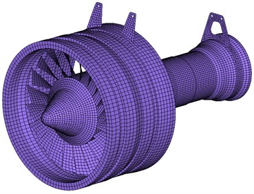
The simulation of pylon separation in this paper mainly focuses on engine, pylon and wing. Because engine and wing are not the key structures, we used simplified models of similar geometrical and mass characteristics instead. Engine size and mass parameters were determined through consulting the corresponding products. The geometric shape of airfoil was obtained basically by extracting the location reference plane in the design of pylon structure. In addition, we establish the main structure model of engine without nacelle, considering that the connection and load transfer between engine and pylon are mainly realized through the installing joints and the thrust bar and that collision of engine with the ground primarily occurs on the front end.
In order to facilitate mesh generation and reduce computational complexity, we extracted the middle surfaces of engine and wing, and meshed the models by using shell elements, as is shown in Fig. 1.
Fig. 1The engine and wing grids
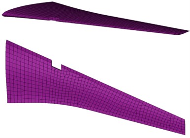
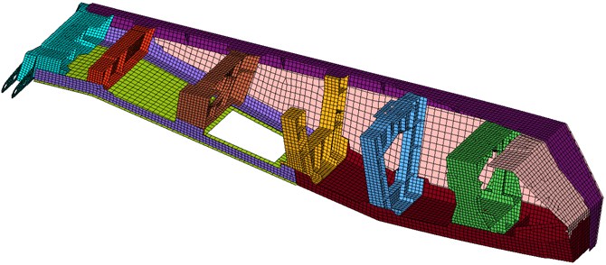
Engine pylon is composed of thin-walled sheet metal parts components (bulkhead, panel, skin and etc.), large size components (joint, linkage and etc.) as well as some appurtenances (edge strip, bush and etc.). Among them, bulkhead, panel, skin, joint and linkage are the main components to bear the weight and transfer the power. Since edge strip and bush have little impact on the analysis of structure loading, there was no need to include them in the process of modeling. Meanwhile the geometrical characteristics such as chamfers and holes were all cleared. Shell elements could still be used to mesh the thin-walled structures, including bulkhead, panel and skin. And the entity parts like joint and linkage were meshed with tetrahedron and hexahedron elements. The geometry clearing and mesh generation of the components are shown in Fig. 2.
Fig. 2Shell element division of thin-walled pylon structure
Tetrahedron elements were applied to mesh the model due to the complexity of the geometry shape of the joint. The use of tetrahedron elements may lead to the flaky or sharp wedge-shaped elements with small collapses in the small size positions such as the stiffener and the groove. These elements are very prone to early distortions during the calculation of large structural deformation and will cause the solving process to terminate. In order to avoid this condition, we should, on the one hand, refine the mesh, and repeatedly check and adjust the low-quality elements; on the other hand, we should also adjust and make improvements to the control parameters and element integration type in the process of calculation so as to achieve a better solution.
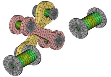
There are 10 fuse pins connecting pylon and wing, respectively located in slant beam, middle lugs, upper connecting rod and lateral connecting rod respectively. Fuse pins are of critical significance to emergency separation. They were involved in the simulation of the impact contact between joint and hole wall, and that of the damage failure of the structure in itself. In the process of impact contact, the structure coupled to load and the variations of momentary speed were not continuous, which dramatically increased the difficulties in achieving the solution and improving its accuracy. Meanwhile, if there fuse pins fails to work, local large deformation will be caused. And if the modeling or the control parameters is improper, it may be very probable to cause series problems such as negative volume in element and node velocity out of range, and lead to failure in achieving the solution. Hence, it is needed to refine the model of fuse pins and select reasonable contact property setting and mode of failure simulation
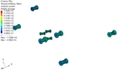
LS-DYNA was used for simulation analysis in this paper. This software simulates the structure failure through defining the material property. It has different modes failure simulation including strain failure and stress failure [12]. This paper qualitatively simulates the damage and failure progress of fuse pins based on the existing material parameters and strain failure of them. The mesh generation of the fuse pins structure (including lateral connecting rod) is shown in Fig. 3.
When the components were meshed, we should assemble the model and set constraints. Engine and pylon were connected by linkages and bolts, and so were wing joints and wing. MPC rigid connection was used in them, because the relative motion between connection parts and the failure of structure were not considered. Bulkhead, panel and skin were all linked by rivets.
In this paper, metal materials are mainly used for the airplane structure. The engine pylon and joint are made out of TC4 titanium alloy, and the fuse pins out of 15-5PH precipitation hardening stainless steel. Materials of engine and wing are more complicated, including various kinds of alloys and composites. The stress-strain status of engine and wing are not considered, because they mainly reflect the mass and inertia in the simulation calculation.
Fig. 3Finite element mesh of fuse pins structure
The material properties of the model are shown in Table 1. The stress-strain curves are shown in Fig. 4.
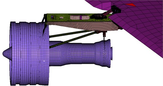
The whole structure mesh model of engine, fuse pins (simplified model) and wing (part) is shown in Fig. 5. There are 251407 elements and 149399 nodes in the whole model.
Table 1Material properties of the components
Components | Material | Density (g/cm3) | Elastic modulus (MPa) | Poisson’s ratio | Yield strength (MPa) | Failure plastic strain |
Pylon | TC4 | 4.4 | 116525 | 0.3 | 860 | / |
Joint | TC4 | 4.4 | 116525 | 0.3 | 860 | / |
Fuse pins | 15-5PH | 7.8 | 200000 | 0.3 | 925 | 0.15 |
Engine | Self-defined | 7.8 | 200000 | 0.3 | / | / |
Wing | Self-defined | 3.2 | 105000 | 0.3 | / | / |
Fig. 4Stress-strain curves of pylon and fuse pins
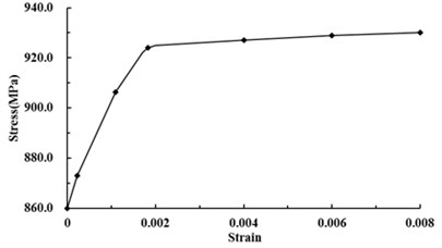
a) Stress-strain curve of TC4
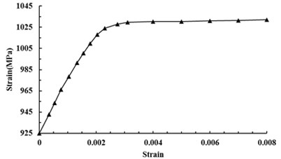
b) Stress-strain curve of 15-5PH
3. Planned pavement emergency landing
There are three main conditions of planned pavement emergency landing that should be considered: lateral landing with a single main landing gear, tail landing with nose gear, and belly landing without landing gear. The simulation analysis model only contained engine, fuse pins and wing, therefore the model needed to be adjusted according to the specific landing modes and the scheduled attitude.
In the progress of lateral landing with a single main landing gear, the aircraft will taxi at a certain roll angle and the wing on the side of the aircraft where the main landing gear is out of work will incline up. Then, the wing will go down and the engine on that side will collide with the ground. The engine bears the vertical impact load and course friction. The nose sinking because of the failure of the nose gear, so the engine hits the ground at a negative angle and the touchdown velocity to be lower than the initial landing speed. According to this analysis, in this condition, the model was adjusted as: the horizontal velocity of the whole engine-pylon-wing structure is 51 m/s, the descent speed 3 m/s, the elevation angle –5°and the roll angle 15°.
Fig. 5The whole mesh model of engine, fuse pins and wing
In the progress of tail landing with nose gear, the tail will slant downwards and the engine will hit the ground at a positive angle as to the fore-body is supported by the nose gear. And the touchdown velocity of engine will be lower than that of nose gear when the nose gear hits ground. The model was adjusted as: the horizontal velocity of the whole engine-pylon-wing structure is 53 m/s, the descent speed 2.8 m/s and the elevation angle 10°.
The flight parameters of planned emergency landing determined by the revised model are shown in Table 2.
Table 2Model parameters of planned emergency landing determined
Condition | Horizontal velocity (m/s) | Descent velocity (m/s) | Elevation angle (°) | Roll angle (°) |
Lateral landing | 51 | 3.0 | –5 | 15 |
Tail landing | 55 | 2.8 | 10 | 0 |
Belly landing | 58 | 3.25 | 0/4/8 | 0 |
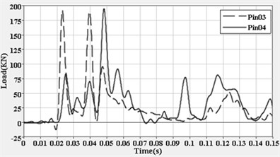
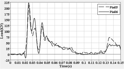
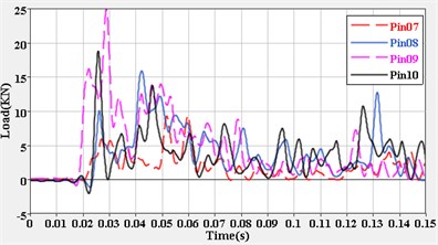
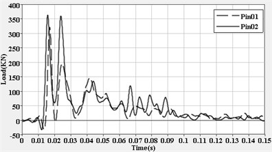
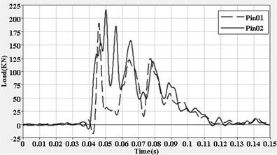
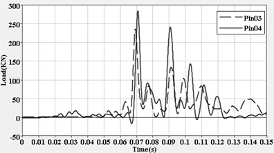
The simulations of emergency landing in the three conditions in Table 2 were completed respectively, and the time-period of calculation was 150 ms, to make it clearer, the fuse pins were numbered as shown in Fig. 6. Among them, No. 1 and No. 2 are the ones at two ends of slant beam; No. 3 and No. 4 are the ones at the left and right middle lugs; No. 5 and No. 6 are the ones at the ends of upper connecting rod; and No. 7-10 are the ones at the lateral connecting rod.
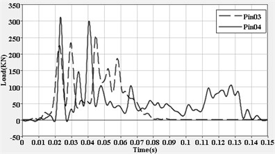
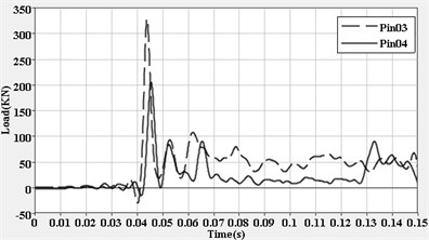
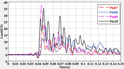
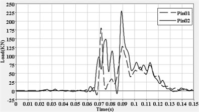
The simulation results showed that damage and failure at different degrees were caused to the fuse pins under the modes and fight parameters in Table 2. The most serious fuse pins failure happened under the condition of lateral landing with a single main landing gear. Complete failure was caused to the pins on slant beam, middle lugs and upper connecting rod. The engine pylon was separated from the wing. Under tail landing and belly landing, the failure was mainly caused to the pin (pin 1) at the joint of the slant beam and wing and the one (pin 6) at the joint of the upper connecting rod and wing, while others were basically intact and could still work. In these conditions, engine pylon was still linked with the wing. The state of failure and that of separation of engine pylon from wing in some of the modes are shown as Fig. 7 and Fig. 8. The contact force-time curves of fuse pins at various operation conditions are shown in Figs. 9-13.
The curves recorded the contact force between fuse pins and corresponding joints during the collision process. Its variation tendency that reflected the interface loading state of the joints may provide reference for the analysis of load transmitting and fuse pins failure. It can be seen from Figs. 9-13, the contact force on pins rapidly reached the peak upon the moment of collision. Slant beam, middle lugs as well as upper connecting rod borne the most of the impact load, and middle lugs borne the largest load in most conditions. The damage and failure of fuse pins were most likely to happen during the peak period. In the following progress, because of the effect of energy absorption and unloading as well as the overall speed decrease caused by the distortion failure of structure, load level remained comparatively lower.
Fig. 6Numbers of fuse pins
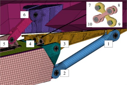
Fig. 7Fuse pins seriously fail and engine pylon separated

a) Fuse pins lose efficacy
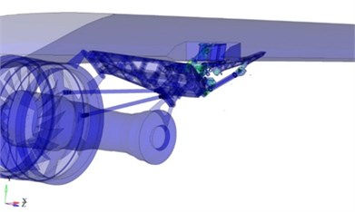
b) Engine pylon separated
Fig. 8Fuse pins largely intact and engine pylon not separated
a) Fuse pins lose efficacy
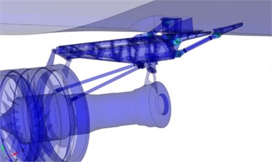
b) Engine pylon separated
It is indicated by Fig. 7 and Fig. 9 that failure occurred first in the fuse pins on upper connecting rod, then in the one on the middle lugs, and finally in the one on the lateral connecting rod and slant beam. The load in lateral connecting rod was significantly higher than that in other landing conditions as a consequence of the large lateral load during lateral landing. The successive failure of fuse pins in different positions leads to the separation of engine with wing, limiting the load transmitting and structural damage, and provided effective prevention against the tear of wing caused by lateral force.
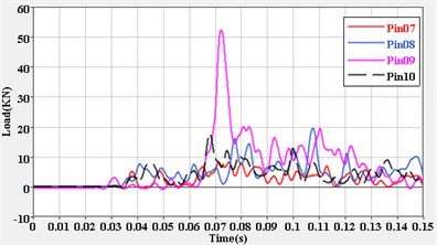
As shown in Fig. 8 and Figs. 10-13, slant beam and upper connecting rod borne serious load during tail landing and belly landing and the contact force values reached successively peaks. The fuse pin No. 1 and No. 6, they were the first to be damaged and their failure came first as their strength was the weakest. The strength of the fuse pins on the middle lugs is much stronger and they were slightly damaged and still working. The fuse pins on lateral connecting rod remained basically intact because the load on the rod was small.
Fig. 9Contact force of fuse pins during lateral landing
a) Force-time curves for slant beam
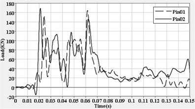
b) Force-time curves for middle lug
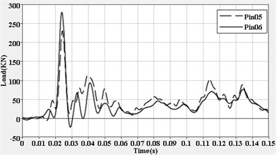
c) Force-time curves for upper connecting rod
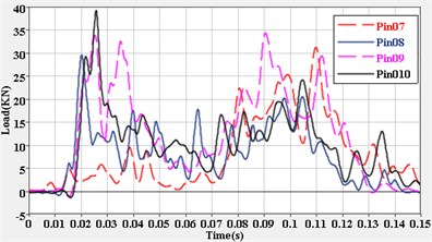
d) Force-time curves for lateral connecting rod
Fig. 10Contact force of fuse pins during tail landing
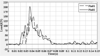
a) Force-time curves for slant beam
b) Force-time curves for middle lug
c) Force-time curves for upper connecting rod
d) Force-time curves for lateral connecting rod
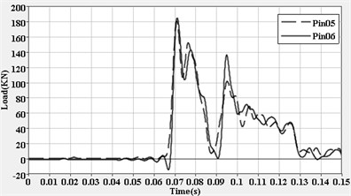
Fig. 11Contact force of fuse pins during belly landing (elevation angle 0°)
a) Force-time curves for slant beam
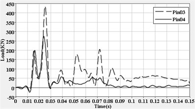
b) Force-time curves for middle lug
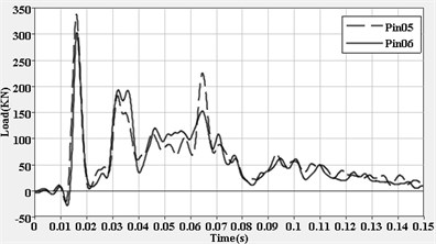
c) Force-time curves for upper connecting rod
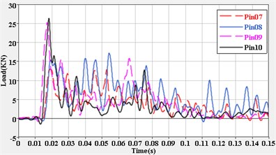
d) Force-time curves for lateral connecting rod
Fig. 12Contact force of fuse pins during belly landing (elevation angle 4°)
a) Force-time curves for slant beam
b) Force-time curves for middle lug
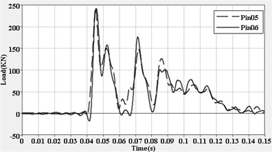
c) Force-time curves for upper connecting rod
d) Force-time curves for lateral connecting rod
The slant beam was in tension and upper connecting rod was in compression during belly landing. This effectively guarantees the course and vertical loading capacity of the engine pylon and maintains structural stability under the impact of lateral load. If the fuse pins on slant beam and upper connecting rod lose efficacy, the loading capacity of engine pylon will be significantly weakened and follow-up load distribution and pylon separation will be influenced. This is really critical to emergency breaking away and the control of the separated body’s motion.
The overload state of structure was monitored through arranging for measurement units in the progress of stimulation. The result recorded showed that the maximal vertical overload nearby the joint at lower surface was 4.85 g in lateral landing, 5.76 g in tail landing and 4.19 g in belly landing. All exceeded the heavy landing decision value 2.2 g but were lower than human tolerance limit value 9 g and the overload value 16 g specified by airworthiness regulations on the structure safety assessment. It was considered that the structure could be damaged under the foregoing landing modes, but was at a low risk of directly damaging the wing tanks and injuring the passengers and the crew members, combining the damage of fuse pins and the load condition of structure reflected by contact force.
Fig. 13Contact force of fuse pins during belly landing (elevation angle 8°)
a) Force-time curves for slant beam
b) Force-time curves for middle lug
c) Force-time curves for upper connecting rod
d) Force-time curves for lateral connecting rod
Based on the above simulation calculation and results analysis, it can be seen that the impact load and overload on the structure of aircraft is not very serious when all or part of the buffer protection from landing gear was lost, because the landing speed in planned emergency landing is close to that in normal landing. At that time, damage and failure shall happen to few fuse pins but was not enough to realize the complete separation of engine pylon. Pylon mainly transmitted and borne the course force and the gravity of engine, so the lateral bearing capacity was relatively weak. As a result, most of the fuse pins will fail and then the pylon will be separated from wing in lateral landing.
Moreover, the structural load reflected by contact force of fuse pins was lower than the measured value of limit load in the static test, though the overload of structure in planned emergency landing exceeded that in normal heavy landing. To ensure the safety of the structure and reduce the maintenance cost, all the fuse pins should be strong enough to bear the overload of from 1.7 g to 2.2 g in heavy landing without any damage.
4. Discussion
It can be seen from the previous simulation result that the peak load of the structure is mainly caused by collision. The time of fuse pins in different positions reaching the peak varies slightly with different load distributions and structural gaps. Under the impact of the peak load, fuse pins fail and fracture successively due to their difference of carrying state and intrinsic strength and then they release the constraint on engine pylon. The sequence of fuse pins’ failures has a direct impact on the realization of pylon separation and whether the trajectory of separated body is suitable.
In this paper, engine pylon was linked with wing through upper connecting rod, middle lugs, slant beam and lateral connecting rod. The first three parts were the main connecting and load-carrying components, while lateral connecting rod was the accessory. Among them, the strength of fuse pins No. 3 and No. 4 on the left and right middle lugs is the highest, and that of fuse pins No. 1 and No. 2 on slant beam comes the second, and that of fuse pins No. 5 and No. 6 on upper connecting rod are weaker. The strength of fuse pins No. 7-10 on the lateral connecting rod is lower than that of those major pins. Analyzing the conditions in previous simulations where the engine pylon failed to separate, we see that in these conditions, fuse pins at slant beam and upper connecting rod failed earlier than those on middle lugs and this leads to the excessive release of the constraint on engine pylon. Additionally, the fuse pins on lateral connecting rod failed earlier than those on middle lugs due to it that the strength of fuse pins on lateral connecting rod is much lower. At that time, the pylon rotates upward and reduces the course friction, causing the further decrease of load on pins. It will make the fuse pins to be unable to fail and the engine pylon not separate completely.
Therefore, in order to achieve the emergency separation of engine pylon under existing structural condition, we have to first realize the fracture failure of fuse pins in at least one side of middle lugs under peak impact load, or followed the failure of pins in upper connecting rod, pins in slant beam fail. Meanwhile, it is determined by the position where pins at connecting rod lose efficacy whether the rod separates from wing with pylon or remains linked in the wing. In general, the size of upper connecting rod is relatively small, and it can stay in wing fairing or separate from wing with pylon. However, slant beam is much longer, and it may poke the wing and damage the fuel tank during the follow-up flight progress if it remains in the wing. Hence, slant beam must be separated from wing with pylon. At last, to avoid the secondary collision and damage to wings and fuselage caused by the separated body, engine pylons should be made to move towards to the outer flank of wing and fall into a location a little distance from fuselage. The trajectory can be realized through coordinating the separation sequence of connecting rod and middle lugs in accordance with the load state in specific conditions.
With the foregoing analyses, to realize the separation between engine pylon and wing, it has to be ensured first the rapid failure of fuse pins on middle lugs under the influence of peak impact load. It can avoid the incomplete fracture of fuse pins in middle lugs under the situation that the follow-up constraint is insufficient and there is a load decrease. Meanwhile, fuse pins No. 1 in slant beam must be separated to bring the separated body into a better state. As for fuse pins No. 5 and No. 6 on upper connecting rod, their failure is determined by the state of loading state. Finally, it is needed to control and coordinate the separation sequence of connecting rod and middle lugs so as to realize a better trajectory of the separated body.
5. Conclusion
This paper focuses on the engine pylon, completes the separation stimulation in planned pavement emergency landing through the establishing of a full-sized engine-pylon-wing finite element model and then obtains the loading response of structure and the failure state of fuse pins during the collision. Damage and failure to a certain extent were caused to fuse pins in all landing conditions. Slant beam, middle lugs and upper connecting rod borne majority of the impact load, and in most conditions, middle lugs undertake the largest load. To realize the separation of engine pylon with wing, it has to be ensured first the rapid failure of fuse pins under the influence of peak impact load and coordinate the separation sequence of connecting rod and middle lugs so as to set a better trajectory for the separated body. This will help realize the emergency breaking away in planned pavement emergency landing.
References
-
Hayduk R. J. Full-Scale Transport Controlled Impact Demonstration. NASA CP 2395, 1985.
-
Fasanella E. L., Widmayer E., Robinson M. P. Structural analysis of the controlled impact demonstration of a jet transport airplane. Journal of Aircraft, Vol. 24, Issue 1, 1987, p. 274-280.
-
Williams M. S., Hayduk R. J. Vertical Drop Test of a Transport Fuselage Section Located Forward of the Wing. NASA TM-85679, 1983.
-
Williams M. S., Hayduk R. J. Vertical Drop Test of a Transport Fuselage Center Section Including the Wheel Wells. NASA TM-85706, 1983.
-
Fasanella E. L., Alfaro-Bou E. Vertical Drop Test of a Transport Fuselage Section Located Aft of the Wing. NASA TM-89025, 1986.
-
Jackson Karen E., Fasanella Edwin L. NASA Langley research center impact dynamics research facility research survey. Journal of Aircraft, Vol. 41, Issue 3, 2004, p. 511-522.
-
Jackson Karen E., Fasanella Edwin L. A survey of research performed at NASA Langley research center’s impact dynamics research facility. 44th AIAA/ASME/ASCE/AHS Structures, Structural Dynamics, and Materials Conference, 2003.
-
Fasanella E. L., Jackson K. E. Crash simulation of a vertical drop test of a B737 fuselage section with an auxiliary fuel tank. Proceedings of the 3rd Aircraft Fire and Cabin Safety Conference, 2001.
-
Jackson K. E., Fasanella E. L. Crash simulation of a vertical drop test of a B737 fuselage section with overhead bins and luggage. Proceedings of the 3rd Aircraft Fire and Cabin Safety Conference, 2001.
-
Wikipedia. US Airways Flight 1549 [EB/OL], http://en.wikipedia.org/wiki/US_Airways_Flight_1549, 2014.
-
FAA extends fuse pins in AD. Federal Aviation Administration, Aviation Week and Space Technology, Vol. 137, Issue 21, 1992, p. 35.
-
LS-DYNA Keyword User’s Manual. LSTC, 2013.
About this article

This work is supported by Jiangsu Provincial Natural Science Foundation of China (No. BK2012795), Operating Expenses of Basic Scientific Research Project (No. NS2014009) and Priority Academic Program Development of Jiangsu Higher Education Institutions.
