Abstract
The effect of weld residual stress on the free vibrational characteristics of cylindrical shell is investigated. Motion equations of cylindrical shell with weld residual stress are established based on Flügge theory, the interaction between weld residual stress and displacements is investigated. The analytical method is applied to calculate the vibrational mode. Weld residual stress can induce the variation of free vibrational characteristics. The amplitude mainly effects the variation magnitude of natural frequency and mode shape, and the distribution dose on the variation trend.
1. Introduction
The welding procedure is widely adopted in the process of submarine assembly and closure. During the welding uneven heating will result in weld residual stress, so it exists widely in the submarine hull [1, 2]. For the large structure, it is difficult to eliminate it though conventional methods. As the basic form of the submarine hull, it is necessary to evaluate the free vibrational behavior of the cylindrical shell with weld residual stress in order to prevent resonance fracture because of external dynamic loads.
Many scholars have done much investigations about weld residual stress, it is increasingly recognized that weld residual stress has the following characteristics [3-5]:
1) Weld residual stress includes tension and compression stress, they exist and balance in one component at the same time. Without the interference of external factors, weld residual stress will maintain stable in a long term.
2) The stress caused by the external load will overlay weld residual stress.
3) When the sum of stress caused by external load and weld residual stress exceeds the yield limit, plastic deformation will produce in the local area, and the distribution and amplitude of weld residual stress will change.
4) Weld residual stress mostly is in plane stress state, and it uniformly distributes along the thickness direction. It varies greatly along the thickness direction only in the thick section weld.
The research about the effect of weld residual stress on the free vibrational characteristics is fewer at present. Gao [6] found that weld residual stress has an influence on the natural frequency of the thin plate by experiments. He also proposed the formula of natural frequency of simple supported thin plate with weld residual stress [7]. The finite element method [8, 9] is used as a solution of vibrational mode of structures with weld residual stress, but it distributes mainly near the weld and varies drastically, so elements near the weld need to be divided very finely. For the large structure with long weld joints, it will spend lots of time on mesh generation.
In order to investigate the effect of weld residual stress on the free vibrational characteristics of cylindrical shell, the interaction between weld residual stress and displacements is investigated and motion equations of cylindrical shell weld residual stress are derived. And the analytical method is applied to calculate the vibrational mode. Finally, the effect of weld residual stress on the vibrational characteristics is discussed in detail.
2. Equations of motion
According to the above features of weld residual stress, the following assumptions are made:
1) Weld residual stress and the stress caused by vibration satisfy the linear superposition.
2) The release of weld residual stress does not occur during the vibration.
3) Weld residual stress maintains perpendicular to the cylindrical shell section during the vibration.
4) Weld residual stress uniformly distributes along the thickness direction.
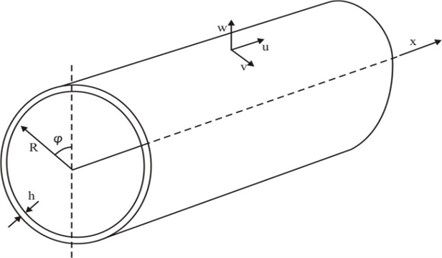
The geometry model of cylindrical shell is shown in Fig. 1. The thickness and radius are respectively denoted by and , is considered small in comparison with other dimensions. , and respectively represent the axial, circumferential and radial directions. , and respectively represent the axial, circumferential and radial displacements. Weld residual stress is generally resolved into two components in previous researches [1], which are respectively perpendicular and parallel to the weld joint. Due to the convenience of derivation, it is resolved into axial component and circumferential component in the cylindrical coordinate here, which are functions of coordinates and .
Fig. 1The geometry model of cylindrical shell
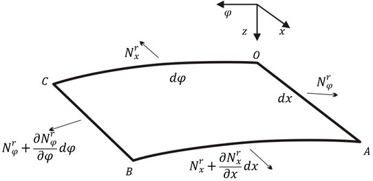
Cut out a element of the shell. The axis is taken perpendicular to the middle plane and positive in a downward direction. Forces acting on the element caused by weld residual stress are shown in Fig. 2. and are normal forces caused by weld residual stress along the and axes.
Fig. 2Element body force caused by weld residual stress
The following will focus on forces caused by weld residual stress during the vibration. The element produces the strain due to the vibration, so lengths at distance from the middle plane on OA and OC section become:
where and respectively denote lengths at distance from the middle plane on and section, and are respectively strains at middle plane in the and axes, and respectively denote curvatures parallel to the and planes.
So areas of and section become:
Flügge [9] proposed that in order to ensure the work done by the weld residual stress is zero, the normal force in the axis during the vibration should be expressed as:
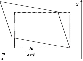
is no longer parallel to the x axis due to the vibration, it rotates around the and axes (shown in Fig. 3), angles are respectively equal to and .
Fig. 3Element body section angle
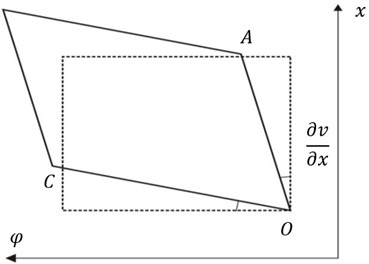
a)
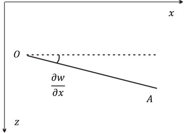
b)
So projections of the normal force in the and axes can be expressed as ignoring the high order term:
where and respectively denote projections of the normal force in the and axes.
When the element is static, which is equal to is parallel to the axis, and there is no projection in other axes. When the element vibrates, variation of in three axes are:
where ,, and respectively denote variations of in the , and axes. They both have the relationship with weld residual stress and displacement, which are called the coupling force.
Similarly, due to the strain caused by vibration, the normal force along the axis can be expressed as ignoring higher order term:
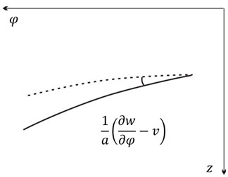
During the vibration, rotates around the and axes (shown in Fig. 4), angles are respectively equal to and .
Fig. 4Element body section angle
a)
b)
Similarly, when the element is static, equal to is parallel to the axis, and there is no projection in other axes. When the element vibrates, variations of in three axes are:
where , and respectively denote variations of in the , and axes, they are also coupling forces.
Since weld residual stress always remains perpendicular to the shell section and uniformly distributes along the thickness direction, it doesn’t produce new couple bending and twisting moments.
Now establish dynamic equilibriums in three axes. Assume that there is no external load acting on the cylindrical shell. Besides and caused by the vibration, there are coupling forces and in the axis. So the equilibrium in this direction can be expressed as:
where and respectively denote the normal force and shearing force along the axis caused by the vibration.
Next establish the equilibrium in the direction. Besides , and , there are coupling forces and . So the equilibrium in this direction can be expressed as:
where and respectively denote the normal force and shearing force along the axis caused by the vibration, denote the normal shearing force acting on the section caused by the vibration.
Then establish the equilibrium in the direction. Besides , and , there are coupling forces and . So the equilibrium in this direction can be expressed as:
where denote the normal shearing force acting on the section caused by the vibration.
Finally establish moment equilibriums in the and directions. Because weld residual stress doesn’t produce new bending and twisting moment, moment equilibriums can be expressed as according to Flügge shell theory [10]:
where and respectively are bending moments caused by normal stress around the and axes, and respectively are twisting moments caused by shearing stress around the and axes.
Forces and moments on the element caused by the vibration can be solved by Flügge theory [10]. Substitute Eqs. (5), (7), (11) and (12) into Eqs. (8)-(10), then free motion equations of the cylindrical shell with weld residual stress are:
where is the material density, , is the Young’s modulus, is the Poisson’s ratio and:
, and are called as coupling terms of weld residual stress and vibration displacement, and denoted by , and for simplification in the following. Weld residual stress is the function of the coordinates and , so its partial derivative of spatial coordinates can't be ignored. Compared with classic motion equations of the cylindrical shell without weld residual stress, Eq. (13) includes coupling terms.
3. Analytical solution
The displacement of the cylindrical shell with simply supported edges can be represented by double trigonometric series as follow [10]:
where , is the length of the cylindrical shell, is the frequency, is the time.
Substituting Eq. (14) into Eq. (13), we can obtain the following equations by making use of the orthogonality of trigonometric series:
where:
When there is a girth weld on the cylindrical shell, the distribution of weld residual stress can be approximately considered to be axisymmetric due to the geometrical axisymmetry. In addition, tensile and compressive residual stress maintain equilibrium in the shell. So weld residual stress is suitable for expressing in the form of single triangular series:
where , , and are amplitudes of weld residual stress, is the positive integer not less than one.
Substitute Eq. (18) into , and , then × equations are established by making use of Appendix Eqs. (A1)-(A4) and (A10)-(A13), which are expressed as matrix form:
where , , , and are clearly shown in Appendix Eqs. (A18) and (A19).
If weld residual stress is not axisymmetric, it will be suitable for expressing in the form of double triangular series:
where and are amplitudes of weld residual stress, and are positive integers not less than one.
Substitute Eq. (20) into , and , then × equations by making use of Appendix Eqs. (A1)-(A17) similarly, which are expressed as matrix form:
where:
and are clearly shown in Appendix Eqs. (A18) and (A20).
Eqs. (19) and (21) are linear systems of equations, the determinant of equation coefficient is set equal to zero, namely:
The eigenvalue and eigenvector can be obtained by solving Eq. (22). The existence of definitely leads to the variation of free vibrational behavior.
4. Discussion
4.1. Natural frequency
Take the two edges simply supported cylindrical shell with weld residual stress for example, which geometry and material parameters are shown in Table 1.
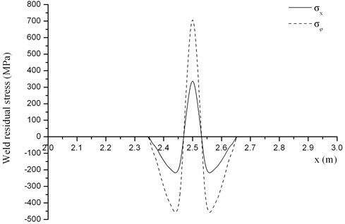
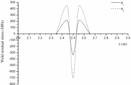
There is a girth weld on the cylindrical shell. Assume that the distributions of weld residual stress at every section are identical, which are shown in Fig. 5.
Table 1Cylindrical shell geometry and material parameters
Geometry parameter | Value | Unit | Material parameter | Value | Unit |
Length | 5 | m | Young’s modulus | 2.1×10¹¹ | N/m2 |
Width | 0.5 | m | Poisson’s ratio | 0.3 | |
Thickness | 0.014 | m | Density | 7860 | kg/m3 |
Fig. 5Weld residual stress distribution No. 1
Firstly, discuss the effect of weld residual stress amplitude on the natural frequency. On the premise of maintaining the distribution (shown in Fig. 6), its amplitude is respectively equal to 100 %, 75 % and 50 %. The first ten natural frequencies under different amplitude solved by the analytical method are shown in Table 2.
Difference of natural frequency under every weld residual stress amplitude is shown in Fig. 6. It can be found that the amplitude of weld residual stress has a great impact on natural frequency, especially variation rate of the first order is up to 6.78 %. With increase of the amplitude, the variation magnitude of natural frequencies grows, but the variation trend basically remains the same. Nowadays high strength steel is widely used as submarine pressure hull. It has the high yield limit, so its amplitude of weld residual stress is higher than general structural steel. Consequently, weld residual stress has the greater impact on natural frequency.
Next the effect of weld residual stress distribution on natural frequencies will be discussed. Two kinds of weld residual stress distribution which have the same amplitude are shown in Figs. 5 and 7.
Table 2The first ten natural frequencies under different weld residual stress amplitude
Order | Without weld residual stress (Hz) | With weld residual stress | |||||
100 % (Hz) | Difference (%) | 75 % (Hz) | Difference (%) | 50 % (Hz) | Difference (%) | ||
1 | 52.07 | 48.55 | –6.78 | 49.46 | –5.01 | 50.36 | –3.30 |
2 | 101.86 | 101.91 | 0.05 | 101.90 | 0.04 | 101.88 | 0.03 |
3 | 108.25 | 102.31 | –5.48 | 103.98 | –3.94 | 105.53 | –2.51 |
4 | 128.24 | 131.21 | 2.32 | 130.49 | 1.75 | 129.75 | 1.18 |
5 | 137.15 | 138.02 | 0.63 | 137.81 | 0.48 | 137.59 | 0.32 |
6 | 181.54 | 180.93 | –0.34 | 181.01 | –0.29 | 181.13 | –0.22 |
7 | 204.32 | 196.12 | –4.01 | 198.67 | –2.76 | 200.92 | –1.66 |
8 | 211.28 | 214.66 | 1.60 | 213.88 | 1.23 | 213.06 | 0.84 |
9 | 229.78 | 230.27 | 0.21 | 229.81 | 0.01 | 229.54 | –0.10 |
10 | 263.02 | 262.96 | –0.02 | 262.98 | –0.02 | 262.99 | –0.01 |
Fig. 6The impact of weld residual stress amplitude on the natural frequency
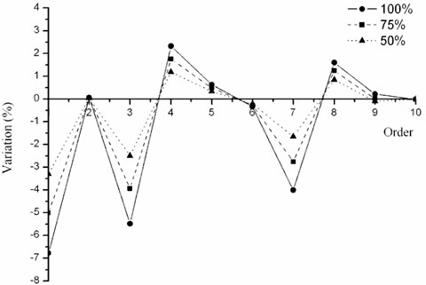
Fig. 7Weld residual stress distribution No. 2
The first ten natural frequencies under different amplitude solved by the analytical method are shown in Table 3.
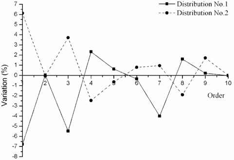
Difference of natural frequency under every kind of weld residual stress distribution is shown in Fig. 8. It can be found that different kind of weld residual stress distribution has different impact on natural frequencies. For example, distribution No. 1 makes the first-order natural frequency decrease, whereas distribution No. 2 makes it increase. Thus, the distribution of weld residual stress plays an important role in the variation trend of natural frequencies.
Table 3The impact of weld residual stress distribution on natural frequencies
Order | Without weld residual stress (Hz) | With weld residual stress | |||
No. 1 (Hz) | Difference (%) | No. 2 (Hz) | Difference (%) | ||
1 | 52.07 | 48.55 | –6.78 | 55.26 | 6.12 |
2 | 101.86 | 101.91 | 0.05 | 101.80 | –0.05 |
3 | 108.25 | 102.31 | –5.48 | 112.27 | 3.72 |
4 | 128.24 | 131.21 | 2.32 | 125.07 | –2.47 |
5 | 137.15 | 138.02 | 0.63 | 136.27 | –0.64 |
6 | 181.54 | 180.93 | –0.34 | 182.99 | 0.80 |
7 | 204.32 | 196.12 | –4.01 | 206.28 | 0.96 |
8 | 211.28 | 214.66 | 1.60 | 207.26 | –1.90 |
9 | 229.78 | 230.27 | 0.21 | 233.74 | 1.72 |
10 | 263.02 | 262.96 | –0.02 | 263.04 | 0.01 |
Fig. 8The effect of weld residual stress distribution on natural frequencies
4.2. Mode shape
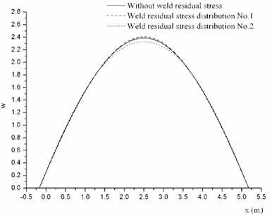
This section will focus on the impact of weld residual stress on the mode shape. The distribution of weld residual stress and are shown in Fig. 5. Firstly, discuss the effect of weld residual stress amplitude on the mode shape. On the premise of maintaining the distribution (shown in Fig. 6), the amplitude is respectively equal to 100 % and 75 %. The typical profiles of several order mode shapes are shown in Fig. 9.
Fig. 9Mode shapes of cylindrical shell with different weld residual stress amplitude at φ= 0
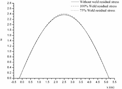
a) The first order mode shape
b) The third order mode shape
It can be found the mode shape of cylindrical shell without weld residual stress is single triangular function, and the mode shape with weld residual stress is the sum of several triangular functions. With the increase of amplitude, the variation of mode shape grows. So the amplitude mainly effects the variation range of mode shape.
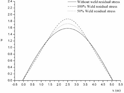
Next the effect of weld residual stress distribution on the mode shape will be investigated. Two kinds of weld residual stress distribution which have the same amplitude are shown in Fig. 5 and Fig. 7. The typical profiles of several order mode shapes are shown in Fig. 10.
It can be found that different kind of weld residual stress distribution has different impact on the shape mode. Distribution No. 1 makes the middle of the mode shape sharper, whereas distribution No. 2 makes it smoother. So the distribution mainly has the influence on the variation trend of mode shape.
Fig. 10Mode shapes of cylindrical shell with different kind of weld residual stress distribution at φ= 0
a) The first order mode shape
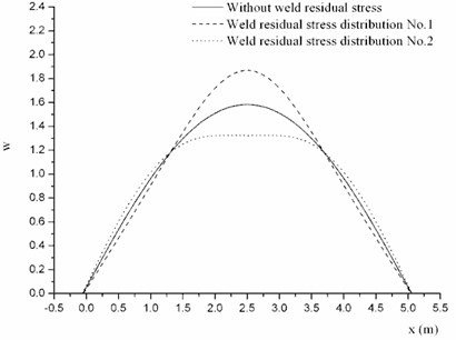
b) The third order mode shape
5. Conclusions
The interaction between weld residual stress and displacements is investigated and derived here, and motion equations of cylindrical shell with weld residual stress are established based on Flügge theory. The analytical method is applied to calculate the vibrational mode. Weld residual stress can lead to the variation of free vibrational behavior. The amplitude has an important effect on the variation magnitude of natural frequency and mode shape, and the distribution does on the variation trend. So the effect of weld residual stress on vibrational characteristics of cylindrical shell can’t be neglected.
References
-
Li L. B., Pan G. S., Wan Z. Q., et al. Numerical simulation and experiments study of welding residual stress of the cone-cylinder pressure hull of high tensile strength steel. Journal of Ship Mechanics, Vol. 14, Issue 10, 2010, p. 1143-1150.
-
Hong J. B., Du Z. M., Hou H. L., et al. Experimental study of residual stress in girth weld of large pressure hull. Ship Engineering, Vol. 28, Issue 5, 2006, p. 14-18.
-
Lee C. K., Chiew S. P., Jiang J. Residual stress study of welded high strength steel thin-walled plate-to-plate joints, Part 1: experimental study. Thin-Walled Structures, Vol. 56, 2012, p. 103-112.
-
Lee C. K., Chiew S. P., Jiang J. Residual stress study of welded high strength steel thin-walled plate-to-plate joints, Part 2: numerical modeling. Thin-Walled Structures, Vol. 59, 2012, p. 120-131.
-
Nickell R. E., Hibbitt H. D. Thermal and mechanical analysis of welded structures. Nuclear Engineering and Design, Vol. 32, Issue 1, 1975, p. 110-120.
-
Gao Y. Y., Su Z. X., Jiao Q. Y., et al. Influence on the natural frequency of component with residual stress. Journal of Mechanical Strength, Vol. 24, Issue 2, 2002, p. 289-292.
-
Gao Y. Y., Liu D. S. Study on estimation of residual stress using modal analysis. Journal of Vibration and Shock, Vol. 25, Issue 5, 2005, p. 111-114.
-
Han Wanmin, Cleghorn William L. Vibration analysis of pre-stressed pressure sensors using finite element method. Finite Elements in Analysis and Design, Vol. 30, Issue 3, 1998, p. 205-217.
-
Zhang Yong Liang, Gorman Daniel G., Reese Jason M. Vibration of prestressed thin cylindrical shells conveying fluid. Thin-Walled Structures, Vol. 41, Issue 12, 2003, p. 1103-1127.
-
Flügge W. Stress in Shells. Spring-Verlag, Berlin and New York, 1973.
About this article

