Abstract
A combined method of thermal and vibratory stress relief (TVSR) to extend effects of vibratory stress relief (VSR) is presented. TVSR was implemented by imposing vibratory load on a workpiece at an assisted temperature. Residual stresses before and after treatment were measured using the modified layer removal method (MLRM) to evaluate the stress variations. A finite element (FE) model was developed to investigate and compare TVSR and VSR treatment on workpieces cut from a 7075 aluminum alloy plate. Thermal influence on TVSR equipment and vibratory treatment of the workpiece was analyzed using this model. Experiments were conducted to validate simulation results. Significant residual stress relief was observed in TVSR, however, effects of VSR were limited.
1. Introduction
Residual stress is a problem often seen during manufacturing. This problem is critical and if left unaddressed could have disastrous consequences, especially in aeronautic and aerospace industries. Typically, residual stress in materials and manufactured parts is due to the presence of thermal gradients or mechanical deformation. Each of these can have a considerable impact on fabrication processes and subsequent service of a workpiece. For instance, effects of two different manufacturing methods on residual stresses were studied by Ma et al. [1] and Wu et al. [2]. Side effects associated with machining distortions would eventually occur [3] as residual stresses develop from the raw stock to the workpiece. Heinz et al. [4] suggested that residual stress should be significantly low to maintain distortions in manufacturing. In addition, stress stability in subsequent service is needed. For example, distortions of an airplane under thermal and vibration load are limited when the airspeed of an airplane is suddenly increased. For these reasons, it is essential to alter residual stress levels throughout the structure.
The objective of residual stress relief is to reduce unsatisfied high stress levels but not to entirely reduce to zero. Residual stress field in a material can be altered by application of thermal, mechanical, electrical or magnetic energy for a fixed time. Conventional technologies such as thermal stress relief (TSR) and vibratory stress relief (VSR) have found widespread application. However, other technologies including strengthening, compression, deep cryogenic treatment, slot peening, explosive treatment, hammer peening, electrical or magnetic treatment are relatively effective in limited situations.
TSR is generally referred to as annealing or tempering and is used as a process to accompany heat treatment. A wide variety of experimental and numerical studies have been carried out and reported in the literature focusing on the evaluation of thermal effects on residual stresses [5]. Residual stresses considerably decrease in magnitude due to mechanical properties variations, which are directly related to the temperature change. However, TSR cannot be used as a method for stress relief for all the applications due to several disadvantages associated with the method. TSR is often time consuming and attention should be given to lowered strength of the material after TSR treatment. As a result, when using this method determination of process parameters such as temperature and duration is critical.
VSR is an alternative method to TSR, which is being increasingly adopted by manufacturers. VSR overcomes the main disadvantages associated with TSR. Considerable effort has been implemented to investigate the effects of TSR [6-11]. In theory, stress relief occurs when yield limit of material is exceeded by the combination of residual stress and dynamic stress [6]. However, excessive VSR treatment has the possibility of damage due to fatigue. This poses a significant problem that effects of traditional VSR should be strengthened for the objects unable to be treated. Actually, one way to allow handling of a workpiece with a high natural frequency is to improve the capacity of VSR equipment. Alternatively, a combination of annealing and vibration treatment can also be used [7].
Here, based on the method proposed by Dawson et al. [7], a combined method of thermal and vibratory stress relief (TVSR) is developed. The modified layer removal method (MLRM) was used to determine the residual stresses field. In order to compare TVSR with VSR, a finite element (FE) model was established based on the Johnson-Cook (JC) constitutive law. Simulation results were validated by experiment. Effects on thermal and vibratory treatment were observed from qualitative and quantitative perspective.
2. MLRM for stress evaluation
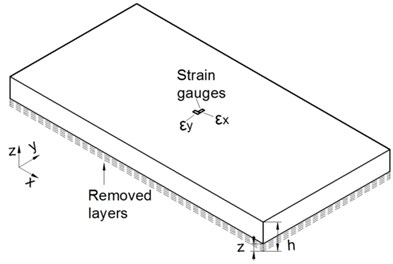
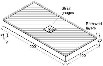
A method for stress measurement is needed to evaluate residual stresses before and after TVSR or VSR treatment. Layer removal method (LRM) is especially suitable in cases where residual stresses are known to vary across the thickness and are assumed to be a function of depth. This method was purposed by Treuting et al. [12] to measure the residual stresses of a plate specimen. Traditionally, variations are determined on one surface as the layers are removed one at a time from the opposite surface. In addition, deformations are measured using strain gauges rather than measuring curvature of the material during in the layer removing, as shown in Fig. 1(a).
Fig. 1a) Schematic depiction of LRM; b) schematic depiction of MLRM and c) experimental application of MLRM
a)
b)
c)
According to the theory of elasticity, equations of strain gauges measurement can be used as follows [12]:
where is Young’s Modulus, is Poisson ratio, is the whole thickness, is the removed depth, , are residual stresses of and direction for the removed layer respectively, , are strains of and direction fitted to the removed layer respectively.
However, this equation is somewhat impractical due to the fitting function, differential and integral of strains as well as unsatisfied sensitivity to the low stress levels. Hence, the MLRM was used to improve effectiveness in the stress evaluation. Strain changes were obtained on the same side of a removed layer compared with the current method. Strain gauges were attached to the center of cutting surface and a small block in the cutting layer was left unprocessed. Then, this block was removed after the measurement. The average value of the measured stress was assumed to be the plate stress state. As illustrated in Fig. 1(b) and (c), this method is an extension of the current method based on existing theory. Due to the property of internal stresses, residual stresses are consequently balanced. Both the direction and direction throughout the whole specimen have to meet the equations as follows:
where σ is residual stress of or direction, is the distance from the midplane, is the cross section.
When a layer is removed, released effects of stresses are equivalent to the combination of external force and moment. The equations are as follows:
where , are force and movement produced by the removed layer respectively.
Residual stresses within the remaining layers redistribute after each removal process. Therefore, stresses calculated using plane stress equations are different from the initial state and are not self-equilibrium. The calculated equations are as follows:
where , are altered residual stresses of and direction respectively.
It is important to calculate the accumulated influence of the force and moment to determine the initial residual stresses. In an effort to avoid complicated calculations, a FE model was utilized. Direct stress results of the modified method were imposed on elements corresponding to each layer in the model. After automatic calculations for the FE model, initial state was restored. It is convenient to maintain analytical, experimental, and numerical modeling methods based on this method.
3. Model and treatment equipment for workpiece
A 7075 aluminum alloy plate was prepared for the quantitative study on the residual stress relief process. It is known that the distribution of residual stresses is virtually symmetric [13]. Chemical compositions of material selected were (wt. %) Si 0.4, Fe 0.3, Cu 1.7, Mn 0.1, Mg 2.2, Cr 2.2, Zn 5.5, Ti 0.2, Al (Bal.). Thermo-mechanical properties varying with temperature were shown in Table 1. Additionally, for the FE model, Poisson ratio was set as 0.3 and thermal expansion coefficient was set as 2.43×10⁻⁵.
Table 1Thermo-mechanical properties of 7075 aluminum alloy plate
Properties | Relation with temperature |
Young’s Modulus (MPa) | 73431-123.35·+0.0517· |
Thermal conductivity (w/m·°C) | 130.5+0.0161·-6×10⁻⁶· |
Specific heat (J/kg·°C) | 960+0.53·-6×10⁻⁶·+6.2×10⁻⁷· |
Density (kg/m3) | 2830-0.513·+2×10⁻⁴· |
Taking into account efficiency and accuracy of FE model, JC constitutive law was employed, which is defined as follows:
where is effective stress, is true strain, is true strain rate, is reference true strain rate, is yield strength, is hardening modulus, is strain rate sensitivity coefficient, , are softening and hardening coefficient respectively, , , are the work, melting and room temperature respectively.
Effects of strain hardening, strain rate hardening and thermal softening can be considered in the JC model. Parameters 503, 303.58, 0.97, 0.77, 0.39 were determined through the split Hopkinson pressure bar tests [14].
Fig. 2Detail of initial residual stress obtained by MLRM
Several workpieces with dimensions of 200 mm (length), 100 mm (width), and 20 mm (thick) were prepared, as shown in Fig. 1(b). Even though they were cut from the same large plate, there was a possibility of stress difference. Therefore, average stresses of two workpieces were taken as initial residual stresses using the MLRM, as shown in Fig. 2. Twenty mesh layers were generated corresponding to the measurement. The maximum compressive and tensile residual stresses were found to exist in the third and sixth layer from the surface layer respectively, which were considered as unsatisfied high stress region.
Natural frequency of the workpiece was 2121.04 Hz, which is quite high for normal vibration exciters. An eccentric mass electric motor was used here to treat the small size but high stiffness workpiece as ranges of frequencies and exciting forces exceed the specifications of the normal vibration exciters.
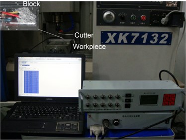
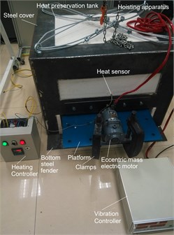
The treatment system is shown in Fig. 3. Two clamps, a vibration platform, a bottom steel fender, three supporters made from micanite, and an eccentric mass electric motor with the controller were included in the vibratory system. Mechanical properties [15] of steel in this system were set as: thermal conductivity 45.1 W/m·°C, specific heat 461 J/kg·°C, thermal expansion coefficient 1.2×10⁻⁵, density 7850 kg/m3 and Poisson’s ratio 0.3. Young's modulus was 212 GPa at 20 °C and 199 GPa at 200 °C. The heating system consisted of a furnace and controller. A steel cover, a heat preservation tank made from the refractory ceramic fiber plates, a heat sensor and heat pipes were included in the furnace, which could be lifted using a hoisting apparatus as required.
Fig. 3Photograph of TVSR equipment setup
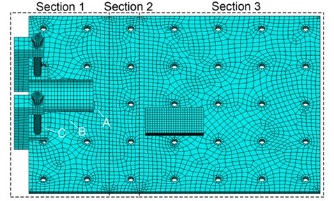
As shown in Fig. 4, the vibration platform with dimensions of 1000 mm ( direction), 700 mm ( direction), and 15 mm ( direction) was recognized as three sections. Section 1 was in contact with air. Section 2 was for temperature transition. Section 3 was covered and heated by the furnace. 32252 nodes and 62048 elements were generated for the model. Arrangement of vibratory equipment was based on modal analysis. The workpiece was placed on the strongly vibratory and easily clamped position of the platform, and supporters were placed on the nodal line regions.
Fig. 4Depiction of FE model. Section 1 to 3 represent different thermal sections for TVSR. A, B and C are reference points for temperature detection
4. Thermal analysis
TVSR is a method to apply initiative warming before and during vibration and cooling after vibration in the majority of cases. Here, thermal effects are explored for altering the vibratory condition. Temperature distribution of the whole equipment is affected by factors such as the heat transfer coefficient of section 1 and treatment temperature in section 3. Three reference points shown in Fig. 4 were selected for temperature detection. Simulations with three levels of heat transfer coefficient and treatment temperature were performed to discover thermal effects. Results are summarized in Table 2, where is the heat transfer coefficient of the section 1, is the treatment temperature in the section 3, , , are the temperatures of reference point A, B, C, respectively, is the frequency of order one affected by temperature distribution, is the frequency of order one affected by both temperature distribution and thermal stresses.
Table 2Temperatures of reference points and frequencies of order one at different thermal parameters
(W/m2·°C) | (°C) | (°C) | (°C) | (°C) | (Hz) | (Hz) |
150 | 125 | 33.40 | 27.23 | 22.10 | 71.14 | 71.80 |
250 | 125 | 29.01 | 24.61 | 22.02 | 71.15 | 71.81 |
350 | 125 | 26.83 | 24.26 | 22.00 | 71.16 | 71.82 |
150 | 150 | 36.16 | 28.50 | 22.12 | 70.86 | 71.52 |
250 | 150 | 30.72 | 25.24 | 22.02 | 70.87 | 71.53 |
350 | 150 | 28.01 | 23.89 | 22.01 | 70.88 | 71.54 |
150 | 175 | 38.93 | 29.77 | 22.14 | 70.56 | 71.22 |
250 | 175 | 32.42 | 25.88 | 22.03 | 70.58 | 71.24 |
350 | 175 | 29.18 | 24.26 | 22.01 | 70.59 | 71.25 |
Temperature was balanced from to the room temperature in section 1 and 2. For the results of , values were found to be satisfactory with and selected. It can be concluded that and within section 1 grows with increasing or decreasing . It was suggested that a relatively high is applied to magnify thermal effects. For actual parameters, was selected to be 175 °C, and , , were measured as 28.8 °C, 24.1 °C, 22.0 °C respectively. was determined as 361.7 W/m2·°C through optimization.
Frequency of order one for VSR was 72.18 Hz, which can be affected by thermal effects. According to in Table 2, frequency decreased when temperature distribution was considered. It can be explained from the decrease in Young’s modulus. From , frequency increased slightly but was still lower than 72.18 Hz for the reason of thermal stresses.
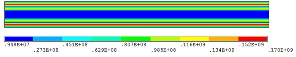
Heating and cooling states of a workpiece were correlated with many parameters, such as heating velocity of furnace, material properties and structure shapes. For isothermal treatment, it was important to enable both core and surface of the specimen to reach the desired temperature. For the top surface layer, relation of temperature to time was measured experimentally, which was associated with the furnace internal ambience. Temperature variation was acquired by thermal simulation for the core and bottom layer. No significant difference was identified and the largest temperature gradient was found to be 0.24 °C. Residual stresses within the workpiece cannot be altered due to this thermal condition. The cooling process condition was approximate to the heating process.
5. TVSR and VSR treatments
Transient analysis of the whole vibratory assembly is a direct but not a reasonable method. At least 20 iterations for the simulation need to be carried out for one cycle time (about 0.014 s) and at least 5 minutes need to be simulated, which result in large computational costs (time and memory). As a result, it is tough to meet convergence properties.
Harmonic analysis using established model was carried out to estimate dynamic stress response in steady state. Combination of dynamic stress and residual stress can be obtained using this analysis. Stiffness damps were set as 1.4×10⁻⁵ in TVSR and 1.6×10⁻⁵ in VSR analysis, which can be calculated by the experimental modal damp ratio. Simulations using same vibratory parameters of both TVSR and VSR were carried out and used in the comparison. Resonant vibratory frequency was put into service, and the load produced by eccentric-mass was 4000 N. Fig. 5 shows the magnitude and phase angle of dynamic stresses. It was concluded that non-uniform responses were present due to the combination of tensile or compression and bending modal shape. However, there is little difference in the magnitudes for TVSR and VSR. is too low to cause stress relief, as no significant vibratory deformation is generated along direction. Thereby the workpiece was treated twice by changing the two principle stress direction along to the direction of vibration platform.
Consequently, steady simulation instead of complicated transient analysis was utilized to study stress relief process after dynamic stress analysis. As twenty states of responses were obtained, simulation was carried out using a series of twenty calculations and was fulfilled via the secondary development. Residual stresses before and after the two treatments were observed, as can be seen in Fig. 6. Plastic flow existed for the case of TVSR due to relative high temperature, which caused sufficient degradation of yield strength temporarily. Residual stresses were firstly relieved in the high stresses region where the softened materials cannot withstand thermal and vibratory loading. Meanwhile, stress redistribution was accompanied. It was revealed that stresses reduction was not uniform throughout the specimen. A maximum stress reduction of 52 % was discovered in unsatisfied high stress region. Plastic deformation did not occur in VSR under the similar conditions because the stresses were lower than and did not exceed the yield strength at room temperature. Namely no stress reduction by simulation was found in VSR.
Fig. 5Comparison of dynamic stress through thickness during VSR and TVSR
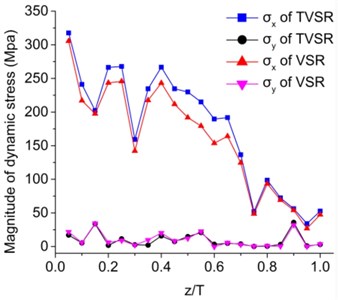
a) Magnitude analysis
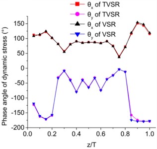
b) Phase angle analysis
Fig. 6Comparison of residual stress in deferent direction through thickness before and after VSR and TVSR, by simulation and experiment
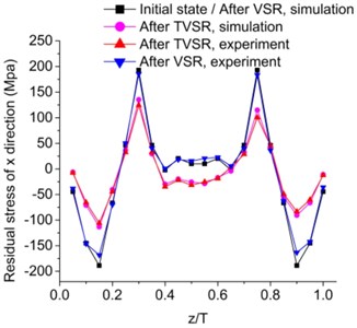
a) direction
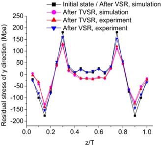
a) direction
A sequence of experiments was performed to verify the analysis results. Specimens were treated by both TVSR and VSR for comparison using the parameters, which were identical to simulation. Experimental residual stresses were measured using the MLRM. Simulated residual stresses reductions were in good agreement with experimental results. A maximum deviation of 14.5 % was discovered in unsatisfied high stress region. Some stress relief was experimentally found in VSR, which may be due to stress concentration. For experimental results, maximum stress reductions of 55.9 % in TVSR and of 13.4 % in VSR were discovered in unsatisfied high stress region.
Vibratory treatment was maintained for 5 minutes for the adequate stress redistribution. For TVSR, preheating was maintained for 20 minutes with the goal of isothermal process. Cooling time was about 30 minutes. Total calculated time for TVSR was about 70 minutes, which was longer than VSR but lower than TSR.
6. Conclusions
A method of TVSR was studied through FE analysis and experimental validation. The MLRM was employed for residual stress evaluation in simulation and experiment. Conclusions can be summarized as follows.
1) The MLRM is convenient to maintain analytical, experimental, and numerical modeling methods. Complicated calculations are avoided and residual stresses are evaluated plainly and effectively in terms of numerical results in FE model. Initial residual stresses and experimental results after treatment can be obtained using this method.
2) An FE model was established based on the JC constitutive law. TVSR equipment should be arranged based on modal analysis. Temperature distribution and thermal stresses were found to decrease the modal frequency in thermal analysis. Non-uniform dynamic stresses were presented in harmonic analysis. Twenty calculations of steady simulation instead of complicated transient analysis were utilized to study stress relief process after dynamic stress analysis. Efficiency of FE method was observed. VSR process was simulated using this FE model as well.
3) Based on the simulation and experimental results, improved efficiency of TVSR compared VSR was demonstrated. TVSR method did indeed contribute to strengthen the effects of VSR. A maximum stress reduction of 52 % in TVSR and no reduction in VSR were discovered in unsatisfied high stress region through simulation. For experimental results, maximum stress reductions of 55.9 % in TVSR and of 13.4 % in VSR were discovered in unsatisfied high stress region.
4) For TVSR, an appropriate temperature causes material softening. Residual stress relief was firstly observed in the unsatisfied high stresses region due to plastic flow. Meanwhile, stress redistribution was accompanied.
5) Process parameters such as temperature, duration, exciting force and vibratory frequency for different workpieces need to be optimized. Eventually the applied temperatures should not to exceed phase transformation point.
References
-
Ma Y. J., Zhang Y. D., Zhang H. W., Xue C. Residual stress analysis of the multi-stage forging process of a nickel-based superalloy turbine disc. Proceedings of the Institution of Mechanical Engineers, Part G: Journal of Aerospace Engineering, Vol. 227, Issue 2, 2013, p. 213-225.
-
Wu Q., Li D. P. Analysis and X-ray measurements of cutting residual stresses in 7075 aluminum alloy in high speed machining. International Journal of Precision Engineering and Manufacturing, Vol. 15, Issue 8, 2014, p. 1499-1506.
-
Ma K., Goetz R., Srivatsa S. K. Modeling of residual stress and machining distortion in aerospace components. Metals Process Simulation, Vol. 22B, 2010, p. 386-407.
-
Heinz A., Haszler A., Keidel C., Moldenhauer S., Benedictus R., Miller W. S. Recent development in aluminium alloys for aerospace applications. Materials Science and Engineering: A, Vol. 280, Issue 1, 2000, p. 102-107.
-
Mackerle J. Finite element analysis and simulation of quenching and other heat treatment processes: a bibliography (1976-2001). Computational Materials Science, Vol. 27, Issue 3, 2003, p. 313-332.
-
Wozney G. P., Crawmer G. R. An investigation of vibrational stress relief in steel. Welding Research Supplement, Vol. 47, Issue 9, 1968, p. 411s-419s.
-
Dawson R., Moffat D. G. Vibratory stress relief: a fundamental study of its effectiveness. Journal of Engineering Materials and Technology, Vol. 102, Issue 2, 1980, p. 169-176.
-
Walker C. A., Waddell A. J., Johnston D. J. Vibratory stress relief-an investigation of the underlying processes. Proceedings of the Institution of Mechanical Engineers, Part E: Journal of Process Mechanical Engineering, Vol. 209, Issue 1, 1995, p. 51-58.
-
Munsi A. S. M. Y. Investigation and Validation of Vibratory Methods for Stress Relieving and Weld Conditioning. Ph.D. Thesis, University of Strathclyde, Glasgow, Scotland, 1999.
-
Kwofie S. Plasticity model for simulation, description and evaluation of vibratory stress relief. Materials Science and Engineering: A, Vol. 516, Issues 1-2, 2009, p. 154-161.
-
Chen Y., Liu B. D., Kang R. Study of vibratory stress relief effect of quartz flexible accelerometer with FEA method. Journal of Vibroengineering, Vol. 15, Issue 2, 2013, p. 784-793.
-
Treuting R. G., Read Jr. W. T. A mechanical determination of biaxial residual stress in sheet materials. Journal of Applied Physics, Vol. 22, Issue 2, 1951, p. 130-134.
-
Jeanmart P., Bouvaist J. Finite element calculation and measurement of thermal stresses in quenched plates of high-strength 7075 aluminium alloy. Materials Science and Technology, Vol. 1, Issue 10, 1985, p. 765-769.
-
Yang Y., Zeng Y., Gao Z. W. Numerical and experimental studies of self-organization of shear bands in 7075 aluminium alloy. Materials Science and Engineering: A, Vol. 496, Issues 1-2, 2008, p. 291-302.
-
Mucha J. Finite element modeling and simulating of thermomechanic stress in thermocompression bondings. Materials and Design, Vol. 30, Issue 4, 2009, p. 1174-1182.
About this article

This study was supported by the National Key Technology R&D Program (China) (Grant No. 2014BAF08B01); and National Natural Science Foundation of China (Grant No. 51105025). The authors are grateful to senior engineer Fangzhi Song, at Research and Application Center of Advanced CNC Machining Technology and Innovation Team of Advanced Manufacturing Technology, for his guidance on experiments.
