Abstract
In this paper, we establish a simplified bridge model in vehicle-bridge dynamic interaction system, and characterize the bridge as laminated composite beams which are discretized as finite beam elements. We adopt the measured dynamic responses of the bridge in the damaged state as input data for damage identification and compute the response sensitivities with respect to the damage indices of the elements to set up the sensitivity matrix. Based on the error between the measured response and the computed one as a minimization criterion, we solve the sensitivity equation by the least-squares method, and then we locate the damage and quantify with the finite element model updating technique. It can be concluded that we only need one measurement point to detect the damage of the bridge, and the identification result is not significantly influenced by the location of the measurement point. Moreover, we can well identify the absolute damage of any beam element by adopting either the displacement response, velocity response or acceleration response.
1. Introduction
Recently, the damage identification based on the global dynamic characteristics of structures has become a topic of very active research in civil and mechanical engineering. Various damage identification methods have been proposed by using such parameters as natural frequencies, mode shapes, modal damping, frequency response functions [1] and stiffness or flexibility sensitivities. Doebling et al. [2] completely reviewed the literature, working on frequency-domain damage detection algorithms for linear structures. Zou et al. [3] proposed a summary on the methods on vibration-based damage detection and health monitoring for composite structures. Housner et al. [4] summarized on state-of-the-art methods in control and health monitoring of civil engineering structures. The basic principle of these methods is to compare the structural behavior in the damaged state with that in the undamaged state. In order to detect the damage locations and to determine the damage extents, it is quite necessary to characterize the undamaged state of the structure. A reliable method can be achieved by comparing the experimentally measured data of a structure in its initial state with those predicted by an initial mathematical model [5]. Based on the principle of structural online health monitoring, it is quite necessary to locate and quantify the damage directly from the time-domain dynamic responses of bridges subject to operating loads such as running vehicles. Many researches have been performed for this purpose. Liu and Chen [6] proposed an inverse technique for identifying stiffness distribution in structures by adopting the structural dynamic responses, where the sensitivity matrices of structural displacements with respect to the stiffness factors were computed by Newton’s method. Cattarius and Inman [7] detected the damage in smart structures from the time histories of structural responses. Chen and Li [8] presented methods to identify both structural parameters and input loads from output-only measurements. Ling et al. [8] presented an element level system identification method with unknown input with Rayleigh damping. Lu et al. [9] investigated the characteristics of dynamic response sensitivities under sinusoidal, impulsive and random excitations, and then adopted them in the structural damage identification. For large civil structures such as long-span bridges, it is normally difficult to excite them by impulsive or sinusoidal loads, so the passing vehicles are more suitable as excitation sources. Zhu and Law [10] investigated the damage detection of simply supported concrete bridges, in which the moving forces and the damage indices are identified at the same time from the measured responses of multiple points. In this paper, a simplified bridge model in vehicle-bridge dynamic interaction system is established, in which the vehicle is characterized as a half-car planar model with six degrees-of-freedom, which is composed of a body mass, a driver and a passenger, and two axles. In order to actually characterize the material property of the bridge, the bridge is modeled as laminated composite beams which are discretized as finite beam elements. The vehicle-induced responses of the bridge in the damaged state are used as input data for damage identification and the response sensitivities with respect to the damage indices of the elements are computed to establish the sensitivity matrix. Based on the error between the measured response and the computed one as a minimization criterion, the sensitivity equation is solved by the least-squares method, and then the damage is located and quantified with the finite element model updating technique.
2. The system governing equation of motion
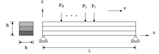
A simply-supported laminated composite beam of length , width and thickness is considered, with the coordinate system placed at the mid-plane of the laminate, with the moving loads , ,..., on the top of the beam, as shown in Fig. 1. All orthotropic layers of the laminate are assumed to be of an equal thickness. The fibers direction is indicated by angle , which denotes the positive rotation angle of the principle material axes of the layer from the -axes. Now we are ready to establish the detailed model of the vehicle-bridge system. We assume that the vehicle travels along the bridge with the velocity , where is the position of the center of gravity (c.g.) of the vehicle body measured from the left-end support of the bridge. Moreover, the steady state displacements of the vehicle are also measured from their static equilibrium positions generated just before the vehicle enters the bridge. Therefore, the gravitational effect of the vehicle weight is considered as an extra portion of variable moving loads acting on the bridge. As shown in Fig. 2, the vehicle is characterized as a half-car planar model with six degrees-of-freedom, which is composed of a body mass, a driver and a passenger, and two axles. The body mass is considered to have the vertical deflection and rotational deflection, while the driver and passenger are restrained to have only their own vertical motion, meanwhile, each axle has its own vertical oscillation. The compositions of the suspension system, the tires, and the passenger seats are characterized by the combination of linear springs and viscous dampers connected in parallel arrangements. To derive the governing equation of motion for the coupled system, the finite element formulation is adopted.
The equations of the coupled motion of the vehicle–bridge system can be expressed as:
where , and are, respectively, the mass, stiffness and damping matrices of the vehicle; , , and are, respectively, the vehicle-bridge interaction matrices; and are, respectively, the displacement vectors of the vehicle and the bridge. The detailed definitions and formulations of the displacement vectors of the vehicle are described in details in Ref. [11]; besides, the displacement vectors of the bridge are formulated by using two-dimensional beam elements; and are, respectively, the force vectors acting on the vehicle and the bridge. By considering the coupling effects between the vehicle and the bridge, the generalized stiffness and damping matrices of the bridge can be derived. By considering the coupling effects between the vehicle and the bridge, the generalized stiffness and damping matrices of the bridge can be derived in the following:
where and are, respectively, the additional stiffness and damping matrices of the wheel-sets on the bridge; is the interpolation function matrix; and denote the first and the second derivative with respect to of , respectively; and are the moving speed and the moving acceleration of the vehicle in the direction, respectively; is the total number of vehicles on the bridge. Eq. (1) can be solved by the Newmark direct integration method. It goes without saying that the displacement, velocity and acceleration responses of location at time can be interpolated from the computed nodal responses.
Fig. 1Bridge-vehicle system: geometry and coordinate system of the laminated composite beam
3. Sensitivity analysis of dynamic response
Generally speaking, it is normally assumed that damage only changes the stiffness of the structure but not the mass [9]. The damage index of the bridge can be denoted as the relative reduction ratio of the norm of the element stiffness. Since the bridge is considered as a laminated composite beam, therefore, the relative damage index and the norm of the th element stiffness matrix in the reference state are, respectively, and , the norm of the element stiffness matrix in the damaged state can be expressed as:
where denotes the norm of a matrix and is the th element stiffness matrix for the laminated composite beam and is the total number of the bridge elements. In order to perform the sensitivity analysis of the dynamic response with respect to damage index, the perturbed equation of motion is achieved by differentiating both sides of Eq. (1) with respect to the system parameter. Assuming the damage index is related only to the stiffness of the dynamic system, the following differentiation equation can be achieved:
It is noted that the velocity response and the displacement response , computed from Eq. (1), are the input data for Eq. (5). As a forward problem, the response sensitivities of the nodes can also be computed from Eq. (5) by the Newmark direct integration method. The response sensitivities of any point with coordinate can be computed easily.
4. Inverse problem solution for damage index vector
The identification problem is defined as calculating the damage index vector of the system provided that the computed responses best match the measured ones. The detailed identification procedure is stated in the following:
Step 1: Update the reference finite element model of the bridge with the identified damage index vector of the th iteration step (the initial damage is usually assumed to be zero, i.e. ), to get and . The displacement response vector and the velocity response vector can be computed by Eq. (1). By substituting , and into Eq. (5), can be computed.
Step 2: Compute the response of the th ( 1, 2,…, ) measurement point at the th ( 1,…, ) time step and its sensitivity by interpolation from the nodal ones. Then construct the time-varying sensitivity matrix . Adopting the penalty function method, the sensitivity equation for damage identification can be obtained as follows:
where is the perturbation in the damage index vector at the th iteration step; is the difference between the computed displacement responses and the measured ones; the superscript “” denotes the measured responses. Generally speaking, the sensitivity matrix of any single measurement point can be used for identification. For a bridge structure with elements, the used response number must be far larger than to make sure that the set of Eq. (6) is over-determined. Eq. (6) can be solved by the least-squares method. Once the increment in the damage index vector is computed, the update damage index vector can be written as:
Step 3: Repeat steps 1 and 2 to get the final value of the damage index vector. The following convergence criterion is adopted:
where denotes the norm of a vector, is the allowable tolerance (%).
It is noted that, the damage identification procedures for velocity or acceleration responses are similar when the corresponding sensitivity matrices are properly generated.
5. Numerical results and discussion
For simplicity, a vehicle traveling at a constant speed of 20 m/s on a bridge is presented here in the numerical computation, meanwhile the 6-d.o.f. passenger-vehicle planar model as shown in Fig. 2 is considered. First of all, a simply supported beam is adopted to perform the analysis of the effect of damage on the vehicle-bridge system, in addition, the bridge shown in Fig. 3 is divided into 31 beam elements. The numerical values of the parameters for the bridge are depicted as follows:
Bridge: 31 m, 1.448×10¹¹ Pa, 9.65×10⁹ Pa, 4.14×10⁹ Pa, 0.3, 1389.23 kg/m3, 15, 1.5 m.
Vehicle: 1794.4 kg, 87.15 kg, 140.4 kg, 75 kg, 75 kg, 3443.05 kg m2, 1.271 m, 1.716 m, 0.481 m, 1.313 m, 66.824 KN m-1, 18.615 KN m-1, 101.115 KN m-1, 14.0 KN m-1, 1190 N s m-1, 1000 N s m-1, 14.6 N s m-1, 50.2 N s m-1, 62.1 N s m-1.
Fig. 2Suspension system of 6-d.o.f. half car model moving on a bridge
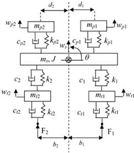
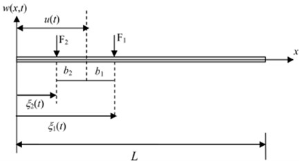
Fig. 3Finite element modeling of simply supported bridge
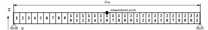
Fig. 4Displacement responses of the midpoint when element 16 suffers different levels of damage
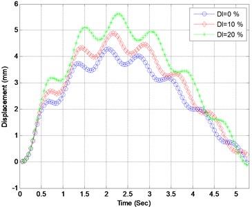
Fig. 5Acceleration responses of the midpoint when element 16 suffers different levels of damage
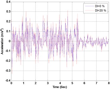
The elements of the bridge are assumed to successively suffer single damage with extents between 0 % and 30 %. At each damage case, the dynamic responses of the bridge are computed based on the vehicle-bridge dynamic interaction model. In Figs. 4 and 5, the displacement and acceleration of the bridge midpoint are presented when element 16 suffers different extent. The distribution of maximum displacements of the bridge midpoint with respect to element damage extent is presented in Fig. 4. It can be found from Fig. 4 that the midpoint displacements of the bridge gets larger when element 16 suffers larger damage, nevertheless, the damage only has little influence on the acceleration response of the midpoint as presented in Fig. 5. Furthermore, the following two phenomena can be observed from Fig. 6:
a) The maximum displacements of the midpoint of the bridge get larger as the damage extent increases.
b) As the damage extent remains unchanged, the maximum displacements of the midpoint of the bridge decreases as the distance of the damaged element to the midpoint increases.
Fig. 6Maximum displacements of the midpoint under different damage cases
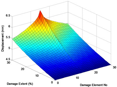
Fig. 7Layout of the continuous bridge model
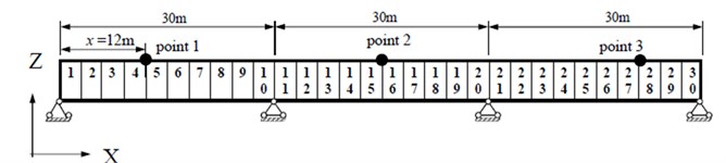
Next, a three-span continuous bridge with spans of 30 m+30 m+30 m shown in Fig. 7 is considered to demonstrate the feasibility and the efficiency of the proposed damage identification method. The bridge is composed of 30 beam element and 31 nodes. The numerical values of the parameters for the bridge and vehicle are considered the same as the previous example. The same vehicle is adopted, which travels onto the bridge from the left support and passes it at a constant speed of 20 m/s. The relative error (RE) is adopted to compute the precision of the identified damage extent. It is denoted as:
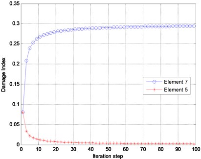
where and are the identified damage index vector and the real one, separately. In Fig. 7, element 7 is considered as the only damaged element with a damage extent of 30 %. The finite element model of the bridge in the undamaged state is known and used as the reference model. Three measurement points are considered, whose distances from the left support of the bridge are 12, 45 and 81 m, separately. The displacement, velocity and acceleration responses at these points are observed and adopted as the input data for damage identification. A typical response of point 2 is presented in Fig. 8. The sampling frequency is 250 Hz, and 2000 forced-vibration response data ( 2000, from 0.3 to 0.7 sec.) are adopted in the identification. Table 1 presents the identification results using the displacement, velocity and acceleration responses. In Fig. 9, the identified results using the acceleration responses of different measurement points are presented. Based on the results from Table 1 and Fig. 9, the following conclusions can be drawn: a) The absolute damage of element 7 is well identified by using either the displacement responses, velocity response or acceleration responses. b) The identified damage using the responses from either of the three measurement points is very close to the real value, implying that the location of the measurement point does not significantly affect the identification result. Fig. 10 presents the damage indices at different iteration steps using the acceleration response measured at point 3. It can be found that the damage indices converge very rapidly to their real values, and only a few iteration steps are required for locating the damage.
Table 1Identification results using different types of response
Point no. | Displacement | Velocity | Acceleration | |||
RE (%) | (%) | RE (%) | (%) | RE (%) | (%) | |
1 | 0.51 | 29.78 | 0.88 | 29.87 | 1.74 | 29.46 |
2 | 0.92 | 29.83 | 1.13 | 29.76 | 1.75 | 29.47 |
3 | 1.73 | 29.54 | 1.76 | 29.54 | 1.53 | 29.94 |
Fig. 8Acceleration response of the bridge midpoint
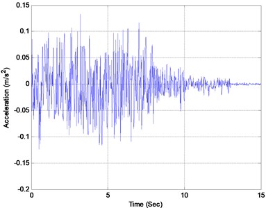
Fig. 9Damage identification using acceleration responses of different points
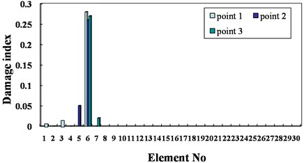
Fig. 10Damage indices versus iteration step
6. Conclusions
In this paper, a simplified bridge model in vehicle-bridge dynamic interaction system is established, in which the vehicle is characterized as a half-car planar model with six degrees-of-freedom, which is composed of a body mass, a driver and a passenger, and two axles. In order to actually characterize the material property of the bridge, the bridge is modeled as laminated composite beams which are discretized as finite beam elements. The vehicle-induced responses of the bridge in the damaged state are used as input data for damage identification and the response sensitivities with respect to the damage indices of the elements are computed to establish the sensitivity matrix. Based on the error between the measured response and the computed one as a minimization criterion, the sensitivity equation is solved by the least-squares method, and then the damage is located and quantified with the finite element model updating technique. Based on the numerical results, the following conclusions can be drawn:
a) It is noted that only one measurement point is required to detect the damage of the bridge.
b) The absolute damage of any beam element is well identified by using either the displacement response, velocity response or acceleration response.
c) The identified damage using the responses from either of the three measurement points is very close to the real value, implying that the location of the measurement point does not significantly affect the identification result.
d) At the beginning of the iteration process, the damage indices converge rapidly, and then converge slowly towards the real value. Only a few iteration steps are required if the goal is to determine the location of the damage.
References
-
Ling X. L., Achintya Haldar P. E. Element level system identification with unknown input with Rayleigh damping. Journal of Engineering Mechanics – ASCE, Vol. 130, 2004, p. 877-885.
-
Doebling S. W., et al. A review of damage identification methods that examine changes in dynamic properties. Shock and Vibration Digest, Vol. 30, 1998, p. 91-105.
-
Zou T., Tong L., Steve G. P. Vibration based model-dependent damage (delamination) identification and health monitoring for composite structures: a review. Journal of Sound and Vibration, Vol. 230, 2000, p. 357-378.
-
Housner G. W., Bergman L. A., Caughey T. K. Structural control: past, present, and future. Journal of Engineering Mechanics – ASCE, Vol. 123, 1997, p. 897-971.
-
Abdel Wahab M. M., De Roeck G., Peeters B. Parameterization of reinforced concrete structures using model updating. Journal of Sound and Vibration, Vol. 228, 1999, p. 717-730.
-
Liu G. R., Chen S. C. A novel technique for inverse identification of distributed stiffness factor in structures. Journal of Sound and Vibration, Vol. 254, 2002, p. 823-835.
-
Cattarius J., Inman D. J. Time domain analysis for damage detection in smart structures. Mechanical Systems and Signal Processing, Vol. 11, 1997, p. 409-423.
-
Chen J., Li J. Simultaneous identification of structural parameters and input time history from output-only measurements. Computational Mechanics, Vol. 33, 2004, p. 365-374.
-
Lu Z. R., et al. Identification of local damages in coupled beam systems from measured dynamic responses. Journal of Sound and Vibration, Vol. 326, 2009, p. 177-189.
-
Zhu X. Q., Law S. S. Damage detection in simply supported concrete bridge structures under moving vehicular loads. Journal of Vibration and Acoustics – Transactions of the ASME, Vol. 129, 2007, p. 58-65.
-
Chang T. P., et al. Vibration analysis of a uniform beam traversed by a moving vehicle with random mass and random velocity. Structural Engineering and Mechanics, Vol. 31, 2009, p. 737-749.
About this article

This research was partially supported by the National Science Council in Taiwan through Grant No. NSC-101-2221-E-327-027-MY2. The author is grateful for the financial support.
