Abstract
A new multiple-input multiple-output (MIMO) proportional-integral-proportional-derivative (PIPD) type fuzzy logic controller (FLC) is proposed for pitch and yaw motion control of a twin rotor system in this study. A fuzzy feedforward compensator for gravity effects on pitch motion of the twin rotor is also designed. Fuzzy logic was preferred for controller design since it can be applied to nonlinear systems and do not require the mathematical model of the system. The twin rotor system is a highly nonlinear system that includes coupling effects between pitch and yaw motions and has similar dynamics to that of a helicopter in certain aspects. Experimental results demonstrate that the proposed controller is able to stabilize the system along with good trajectory tracking performance.
1. Introduction
In recent years, the control of twin rotor systems has continuously attracted researchers. This is mainly due to the fact that the twin rotor system has similar dynamics to that of a helicopter in certain aspects [1] and it has highly coupled, unstable and nonlinear dynamics [2]. Different control approaches have been applied to control the coupled pitch and yaw dynamics of the twin rotor system. Bayrak et al. [3] constructed a twin rotor multiple-input multiple-output (MIMO) system in their laboratory and applied proportional-integral-derivative (PID) controller for set point regulation. Ahmad et al. [4] designed a linear quadratic Gaussian control to control only the pitch movement of an experimental twin rotor system. Yang and Hsu [5] developed an adaptive control approach based on the backstepping concept for the two degrees of freedom helicopter and evaluated its performance via experiments. Wen and Lu [2] studied the decoupling control of a twin rotor MIMO system by designing a robust deadbeat control technique and presented simulation results. To control the positions of the pitch and yaw angles in a twin rotor system Tao et al. [6] presented a parallel distributed fuzzy linear quadratic regulator based on the derived fuzzy Takagi-Sugeno model and verified the performance of the controller via simulations. Juang et al. [7] presented a fuzzy PID control scheme with a real-valued genetic algorithm to the set point control of a twin rotor MIMO system. They evaluated their fuzzy PID controller that uses 343 rules in real time. In [1] a fuzzy-sliding and fuzzy-integral sliding controller was designed to control the position the yaw and pitch angles of a twin-rotor MIMO system. Simulation results confirmed that a better performance was obtained if compared with a PID controller coupled with a modified real-value-type genetic algorithm. Jahed and Farrokhi [8] considered an adaptive fuzzy controller to control the yaw and pitch angles of a twin rotor MIMO system (TRMS) in two degrees of freedom. They have used gradient descent algorithm in order to update the parameters of the fuzzy controller. Aras and Kaynak [9] performed simulation studies for the twin rotor system where they have used interval type-2 fuzzy neural controller. Soh et al. [10] designed a fuzzy logic controller (FLC) for the twin rotor system and investigated the effects of changing the rule numbers and widths of the membership functions on system performance.
In this study fuzzy logic is preferred for controller design since it does not require the mathematical model and gives the ability to use expert’s knowledge concerning dynamics of the system. As it is well known FLC is based on the fuzzy set theory presented by Zadeh [11] and there are mainly two types of FLCs. The first one is the proportional-derivative (PD) type FLC in which the error and its derivative are used as inputs and the control signal is the output. The second one is the proportional-integral (PI) type FLC in which error and its derivative are used as inputs and the incremental change in control signal is the output. Transient response of the PD type FLC is better than the PI type FLC, but in some cases steady state error cannot be removed for PD type fuzzy logic controlled system [12]. In fact, it is possible to design a PID type FLC but it requires a 3-D rule base that is difficult to construct and its use is rare if compared with PI and PD type FLCs [13-14]. Therefore, in this study a new MIMO PIPD type FLC is proposed for the control of a twin rotor system. This controller combines the advantages of the PI and PD type FLCs. A fuzzy feedforward compensator (FFC) was also designed that compensates for the gravity effects present in pitch motion dynamics. Rest of the paper is organized as follows: After presenting the experimental twin rotor setup in Section 2, the details of the proposed controller is explained in Section 3. Then in Section 4, performance of the proposed controller is validated via experiments. Finally, conclusions are drawn in the last section.
2. Twin rotor system
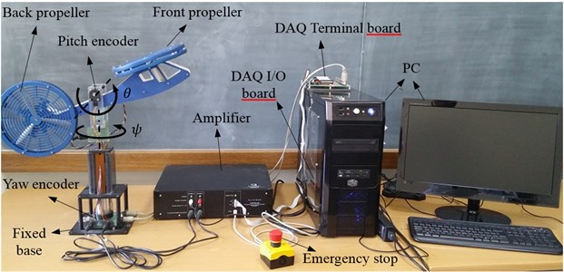
Although the twin rotor system is a simplified model, it has similar dynamics to that of a real helicopter in certain aspects [1]. From the automatic control point of view this system attracted many researchers since it possesses interesting control challenges [15]. Therefore, the twin rotor system constitutes a good introductory level test bed for the studies concerning unmanned air vehicles, where the designed control algorithms may be tested. The twin rotor system shown in Fig. 1 is introduced in this section. It consists of a two degrees of freedom helicopter model mounted on a fixed base. There are two propellers, namely front and back propellers that are driven by two separate DC motors. This is why it is called as twin rotor system. The thrust force generated by the front propeller moves the twin rotor about the pitch axis (horizontal axis) and similarly the thrust force generated by the back propeller moves the twin rotor about yaw axis (vertical axis). The rotations about the pitch and yaw axes are measured via two encoders. The pitch encoder has a resolution of 4096 counts per revolution that is the effective position resolution is 0,0879 degrees and yaw encoder has a resolution of 8192 counts per revolution that is the effective position resolution is 0,0439 degrees [16]. The range of pitch motion/angle () is between –40.3 and 36 degrees whereas the range of yaw motion/angle () is 360 degrees that is the system can rotate freely about yaw axis. The twin rotor is horizontal when the pitch angle is zero. The encoder data is collected via Quanser data acquisition (DAQ) terminal and input/output (I/O) boards. The control voltage commands produced by the designed control algorithm are sent to the amplifier that powers the DC motors of the propellers. The limits for pitch and yaw control voltages are ±24 V.
Fig. 1Experimental setup for the twin rotor system
3. Controller design
A new MIMO PIPD type fuzzy logic controller with fuzzy feedforward compensator (MIMO PIPD FLC + FFC) is designed in this section. Fuzzy logic is preferred since it does not require the exact mathematical model of the system under consideration and it can be applied to linear and nonlinear systems as well. Additionally it gives the ability to use the experts’ knowledge during controller design. It is well known that with the classical configuration of the FLCs namely PD type FLCs, where error () and its time derivative () are used as inputs and control signal () is the output, there may be steady state errors on the output variable of the system. Thus in certain cases PI type FLCs, where error () and its derivative () are the inputs and incremental change in control signal () is the output, may be preferred to remove the steady state error. On the other hand PI type FLCs may cause stability problems. Therefore, in this study, effects of PI and PD type FLCs are combined to control the twin rotor system. Additionally, a single-input single-output fuzzy feedforward compensator is also used for pitch motion, which is designed to compensate for the gravitational torque. The general structure of the controller for pitch motion is presented in Fig. 2. The final control signal for the pitch motion is calculated as:
The structure of the controller for the yaw motion is similar to that of pitch motion controller. The main differences are that there is no feedforward compensator for yaw motion and the inputs are yaw error and its derivative, that is only PIPD part of the controller is used for yaw motion control. The final control signal for the yaw motion is calculated as:
Fig. 2General structure of the proposed controller for pitch motion
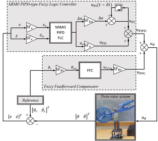
Triangular membership functions are used for the fuzzification of the input and output variables as seen in Fig. 3. Here NVB, NB, NM, NS, Z, PS, PM, PB, PVB denote negative very big, negative big, negative medium, negative small, zero, positive small, positive medium, positive big and positive very big, respectively. The output membership functions of the feedforward compensator are defined on [0 1] interval, and all other membership functions are defined on [–1 1] interval. Scaling factors () are used to map the crisp input and output variables to their fuzzy universe of discourse and subscript n stands for the normalized variable.
The fuzzy logic inference rules are in the following form for the MIMO PIPD part of the proposed controller:
here , and , are input and output membership functions, respectively.
Fig. 3Membership functions of the: a) input variables, b) output variable of the FFC part and c) output variables of the MIMO PIPD part of the proposed controller
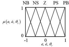
a)
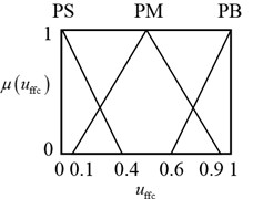
b)
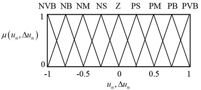
c)
The following manner is used during the construction of the rule base presented in Table 1 for the MIMO PIPD part of the FLC for pitch and yaw motion control. Suppose that the system output is far away from the desired output i.e. error is PB and its time derivative is Z then and are selected to be PM in order to decrease the error. Consider the case where is Z but it tends to increase because is NB, then and should not be zero and they are selected to be NM. Consider the case that both and are Z, which is the desired case, therefore and are selected to be Z.
Table 1Rule table for computing unand Δunfor the MIMO PIPD FLC
NB | NS | Z | PS | PB | ||
NB | NVB | NB | NM | NS | Z | |
NS | NB | NM | NS | Z | PS | |
Z | NM | NS | Z | PS | PM | |
PS | NS | Z | PS | PM | PB | |
PB | Z | PS | PM | PB | PVB |
Table 2Rule table for computing uffcn for the fuzzy feedforward compensator
NB | NS | Z | PS | PB | |
PS | PM | PB | PM | PS |
For the construction of the rule base of the pitch motion feedforward compensator part of the fuzzy logic controller presented in Table 2 the following manner is used. There is a gravitational torque about the pitch axis which is generated by the weight of the twin rotor at the mass center that is far away from the pitch axis. Since the gravitational torque will reach to its biggest values when pitch angle is approximately zero, the feedforward control part is selected to be PB when is Z. Similarly, since gravitational torque decreases with increasing pitch angle then feedforward control part is also decreased.
4. Experimental Results
In this section experimental results are presented for the designed controllers. Initially the twin rotor system is at rest and corresponding initial pitch and yaw angles are –40,3 and 0 degrees, respectively. The types of the reference trajectories for the pitch and yaw motions are both square waves where the amplitude is 10 degrees and frequency is 0,05 Hz. The experiments are carried out with 1 ms sampling time. For comparison purpose, the proposed MIMO PIPD FLC+FFC is also compared with the PI FLC+FFC and PD FLC+FFC. The PI FLC+FFC can be obtained by excluding the PD part from the proposed MIMO PIPD FLC+FFC controller and the PD FLC+FFC can be obtained by excluding the PI part from the proposed MIMO PIPD FLC+FFC controller. It should be noted that the FFC part is used only for the pitch motion. The scaling factors are tuned by trial during real-time application and they are in Table 3.
Table 3Scaling factors of the designed controllers
PI FLC + FFC* | PD FLC + FFC* | MIMO PIPD FLC + FFC* | ||||
Pitch | Yaw | Pitch | Yaw | Pitch | Yaw | |
0,01 | 0,001 | 0,15 | 0,1 | 0,1 | 0,1 | |
0,01 | 0,01 | 0,06 | 0,1 | 0,06 | 0,06 | |
0,1 | 0,1 | – | – | 0,12 | 0,12 | |
– | – | 100 | 500 | 200 | 150 | |
0,7854 | – | 0,7854 | – | 0,7854 | – | |
19 | – | 19 | – | 19 | – | |
* The FFC is used only for pitch motion | ||||||
Fig. 4Comparison for the tracking performances of the designed controllers
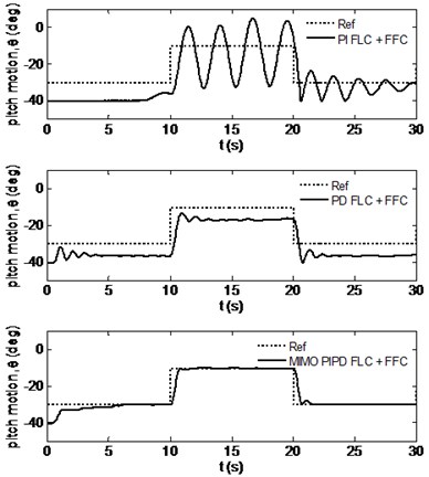
a) Pitch motion
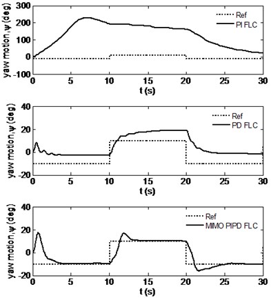
b) Yaw motion
Fig. 4 presents the time responses of the pitch and yaw motions for all the designed controllers. From this figure it is seen that with the PI FLC+FFC the twin rotor system could not be stabilized since there are big oscillations in the pitch angle and reference yaw angles could not be tracked. From the same figure it is seen that if PD FLC+FFC is used, the twin rotor system now can be stabilized but there exist big steady state errors for the pitch and yaw angles that could not be removed. On the other hand, it is deduced from this figure that by using the proposed MIMO PIPD FLC+FFC the twin rotor system was stabilized without steady state errors, that is the reference angle trajectories were tracked. This demonstrates the success of the proposed controller.
Fig. 5 presents the control voltages applied to the DC motors that were calculated by the designed FLCs. It is seen that the control voltages are within the allowed ranges. Only for the PD FLC+FCC case the yaw control voltage saturates for a short time period at the beginning of the motion which has not degraded the performance very much.
Fig. 5Control voltage signals produced by the designed controllers
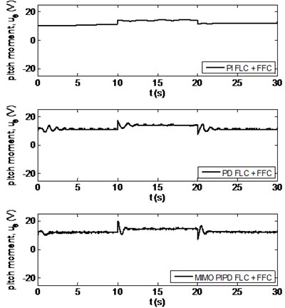
a) Pitch motion
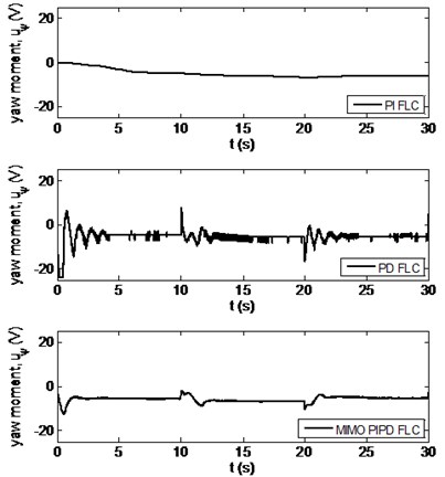
b) Yaw motion
Finally, the integral square error (ISE) performance indices [17] for the designed controllers are calculated from the experimental results and presented in Table 4. The ISE index is calculated for both tracking errors () and control voltages (). Here, ISE() represents the tracking performance for the pitch/yaw motion and ISE() represents the control effort used for the actuation of the DC motor of the related propeller. If the results on Table 4 are investigated it is observed that the proposed MIMO PIPD FLC+FFC provides the smallest performance indices for both tracking errors and control voltages if compared with the PI FLC+FFC and PD FLC+FFC cases. Therefore, it is deduced that proposed MIMO PIPD FLC+FFC stabilized the twin rotor system with smallest tracking errors along with small power requirements that verifies the superior performance of the proposed controller.
Table 4Performance indices for the designed controllers
ISE() | ISE() | ISE() | ISE() | |
PI FLC + FFC* | 3115,7 | 677940 | 19000 | 29738 |
PD FLC + FFC* | 1585,2 | 2792,8 | 19000 | 29554 |
MIMO PIPD FLC + FFC* | 355,9 | 1152,6 | 5096 | 1039 |
* The FFC is used only for pitch motion | ||||
5. Conclusion
In this study a new FLC scheme for the control of a twin rotor system has been proposed. It is a MIMO PIPD type FLC for both pitch and yaw motions where for pitch motion an additional FFC was also designed. Proposed controller was applied on a real twin rotor system in laboratory. The experimental results verified that the designed controller performed better if compared with PI and PD type FLCs. Finally, the author believes that the proposed MIMO PIPD FLC with/without the FFC part, which is specially designed for the pitch motion control of the twin rotor, may also be used for the control of unmanned air vehicles, active suspension systems of automobiles, industrial robotic manipulators, seismic vibration isolation systems and so on. This is possible since the proposed controller is model-free and applicable to nonlinear systems.
References
-
Wen P., Lu T.-W. Decoupling control of a twin rotor MIMO system using robust deadbeat control technique. IET Control Theory and Applications, Vol. 2, Issue 11, 2008, p. 999-1007.
-
Tao C.-W., Taur J.-S., Chang Y.-H., Chang C.-W. A novel fuzzy-sliding and fuzzy-integral-sliding controller for the twin-rotor multi-input – multi-output system. IEEE Transactıons on Fuzzy Systems, Vol. 18, Issue 5, 2010, p. 893-905.
-
Bayrak A., Dogan F., Tatlicioglu E., Ozdemirel B. Design of an experimental twin-rotor multi-input multi-output system. Computer Applications in Engineering Education, Vol. 23, Issue 4, 2015, p. 578-586.
-
Ahmad S. M., Chipperfield A. J., Tokhi M. O. Dynamic modelling and linear quadratic Gaussian control of a twin-rotor multi-input multi-output system. Proceedings of the Institution of Mechanical Engineers, Part I: Journal of Systems and Control Engineering, Vol. 217, Issue 3, 2003, p. 203-227.
-
Yang J.-H., Hsu W.-C. Adaptive backstepping control for electrically driven unmanned helicopter. Control Engineering Practice, Vol. 17, 2009, p. 903-913.
-
Tao C. W., Taur J. S., Chen Y. C. Design of a parallel distributed fuzzy LQR controller for the twin rotor multi-input multi-output system. Fuzzy Sets and Systems, Vol. 161, 2010, p. 2081-2103.
-
Juang J.-G., Liu W.-K., Lin R.-W. A hybrid intelligent controller for a twin rotor MIMO system and its hardware implementation. ISA Transactions, Vol. 50, 2011, p. 609-619.
-
Jahed M., Farrokhi M. Robust adaptive fuzzy control of twin rotor MIMO system. Soft Computing, Vol. 17, 2013, p. 1847-1860.
-
Aras A. C., Kaynak O. Interval type-2 fuzzy neural system based control with recursive fuzzy c-means clustering. International Journal of Fuzzy Systems, Vol. 16, Issue 3, 2014, p. 317-326.
-
Che Soh A., Abdul Rahman R. Z., Sarkan H. Md., Yeo L. T. Intelligent control of twin-rotor mimo system using fuzzy inference techniques. International Review of Aerospace Engineering, Vol. 6, Issue 1, 2013, p. 28-39.
-
Zadeh L. A. Fuzzy sets. Information and Control, Vol. 8, 1965, p. 338-353.
-
Lee J. On methods for improving performance of PI-type fuzzy logic controllers. IEEE Transactions on Fuzzy Systems, Vol. 1, Issue 4, 1993, p. 298-301.
-
Mudi R. K., Pal N. R. A robust self-tuning scheme for PI- and PD-type fuzzy controllers. IEEE Transactions on Fuzzy Systems, Vol. 7, Issue 1, 1999, p. 2-16.
-
Xu J. X., Hang C. C., Liu C. Parallel structure and tuning of a fuzzy PID controller. Automatica, Vol. 36, 2000, p. 673-684.
-
Kendoul F. Survey of advances in guidance, navigation, and control of unmanned rotorcraft systems. Journal of Field Robotics, Vol. 29, Issue 2, 2012, p. 315-378.
-
Quanser 2 DOF Helicopter User and Laboratory Manuals. Quanser Inc., Revision 2.3.
-
Ogata K. Modern Control Engineering. Prentice Hall International, USA, 1990.
