Abstract
Amongst the robotics and autonomous systems, robot manipulators have proven themselves to be of increasing importance and are widely adopted to substitute for human in repetitive and/or hazardous tasks. In this paper, the purpose is to research on dynamic performance and motion control of robot manipulator for the more precise, crucial and critical tasks in industry. Firstly, the forward and inverse kinematics was accurately described by obtaining the link transformation matrices from each joint in robot manipulator. To find admissible solutions along the path, the workspace of the manipulator was determined by joint limit condition and validated by actual measurement. And then, the dynamic performance of robot manipulator is researched by using the forming flexible multi-body system. Furthermore, the frequency response curves are obtained by exciting vibration simulation based on vibration model, which the predicted method was validated by comparing simulation and experimental results. Finally, the control system architecture was given and the grasping process was conducted by gripper based on motion trajectory control in the workspace.
1. Introduction
Nowadays, robotic manipulators are used in various applications and environment. Each of them has their own complexity and uniqueness in order to fulfill the task given. However, many advance technologies are severely restricted in commercial system due to limitation of the controller rather than the manipulator arms. The tool or end-effectors is to follow a planned trajectory to manipulate objects or carry out the task in the workspace [1-3]. This requires control of position of each link and joint of the manipulator to control both the position and orientation. Robot gripper were indispensable for achieving productivity and flexibility in fully automated production lines, where they are used for a wide variety of tasks, ranging from material handling and assembly to cutting, welding, gluing, and painting. [4, 5].
In order to obtain the satisfied grasping requirements, robot manipulator needs to work accurately and efficiently. The vibration and deformation of robot manipulator will be having important effect on grasping quality. It is a main research work to reduce and void vibration for ensuring the manipulator will not generate self-oscillation when it works in the range of rated power. In addition, the dynamic error is provide to motion control to improve grasping precision. Good dynamic characteristic of robot manipulator will be more important with gradually improvement of grasping property. Therefore, vibration analysis has been an indispensable research of robot manipulator in design and manufacture process [6-8].
There are some literature researches on dynamic performance and motion control. In [9], Zaeh al. have researched the simulation of machining performance by integrating finite element and multi-body simulation for machine tools, and compared the cutting force of simulation with that of measure. In ref [10], Altintas et al. have presented finite element analysis of machine tools, coupled simulation of structural dynamics and control loops of machine tools in macroscopic view. In [11], Andreas et al. have proposed integrative simulation framework of Ornithopter was validated by the wind tunnel test data and modeled by using the multi-body dynamics software and finite element analysis software. He proposed method has been verified by comparing experimentally measured forces of a flapping-wing and the corresponding simulation results. In [12], Greco et al. have presented a simple formulation to deal with flexible multi-body dynamic systems by the finite element method and proposed methodology is based on the minimum potential energy theorem written regarding nodal positions. In ref Lin [13], the various joint movements captured by motion sensors were recorded and the results applied in controlling robotic arms. Mohamed [14] presents investigations into the applications and performance of positive and negative input shapers in command shaping techniques for the vibration control of a flexible robot manipulator. Jamshed et al. [15] have proposed model makes it possible to control the manipulator to achieve any reachable position and orientation in an unstructured environment. The developed model is demonstrated by experimental measuring.
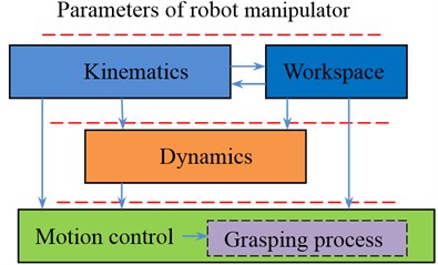
The paper mainly focuses on the dynamic performance and motion control of 3-finger robot gripper. It is divided into four main sections; the first, entitled the kinematic theory and workspace, will be given the model of forward kinematics and inverse kinematics, and the workspace was determined by an analytical method. The second section, the frequency response function of robot manipulator, will be obtained by exciting vibration simulation based on vibration model. The third part, motion control and grasping process of robot manipulator, will be conducted by gripper based on motion trajectory control. Finally, in section four, some conclusions from this study are given. In this paper, the architecture is shown in Fig. 1.
Fig. 1Architecture of research contents
2. Kinematic theory and workspace
A spatial transformation between two consecutive links of a serial robot manipulator can be described by a set of parameters in Fig. 2, namely , , and . The definitions of these parameters are given as follows: is the angle from the axis to the axis measured about axis, the distance between from the axis to the axis measured along axis, the angle form the axis to the axis measured about axis, and the distance from the axis to the axis measured along axis.
Fig. 2Joints and link coordinates of the robot manipulator
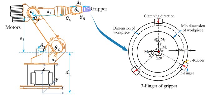
Parameters of all links and joints are shown in Table 1. Technical data is as following: Max. permitted finger length: 60 mm. Max. permitted weight per finger: 0.6 kg. Repeat accuracy: 0.01 mm. Grasping force: 1000 N. The indicated moments and forces are statics values, apply per base jaw and may occur simultaneously. 48 Nm; 76 Nm; 44 Nm. Magnetic switch type: smc D-A93.
Table 1Link parameters of the robot
Link | Variable range | Max. speed | ||||
1 | 90° | –185°-185° | 156°/s | |||
2 | 0 | 0 | –155°-35° | 156°/s | ||
3 | 90° | 0 | –130°-154° | 330°/s | ||
4 | 0 | –90° | –350°-350° | 330°/s | ||
5 | 0 | 90° | 0 | –130°-130° | 615°/s | |
6 | 0 | 0 | –350°-350° | 156°/s |
2.1. Forward kinematics analysis
Forward kinematics refers to the geometrical representation of a coordinate frame located at any part of the manipulator with respect to a fixed coordinate frame usually attached to the base of the manipulator. The most common analysis is made over the tip of the manipulator, typically known as end-effectors, where the tool of the manipulator is located [6]. The formulation derived from the forward kinematics is used to define the end-effectors position and orientation.
Using these parameters, the general form of the transformation matrix for adjacent coordinate frames, and is obtained as:
The transformation of the link coordinate frame into the base coordinate frame of the robot manipulator is given by:
where is the transformation matrix of the frame coordinate system of link () with respect or the frame coordinate system of the link (1), where 0, 1, 2,…, .
Fig. 3Motion trajectory of robot gripper
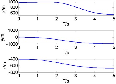
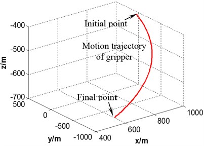
The initial joint angles are and the terminated joint angles are in joint coordinate system. Trajectory of manipulator is simulated based these parameters in space. It can be seen in Fig. 3 that the trajectory curve from to is smooth, which is stable in motion process.
2.2. Inverse kinematics analysis
In robotics, finding the joint angles of a manipulator to locate the end-effectors at a given position and orientation is known as inverse kinematics [2]. Solving the inverse kinematics problem is essential for pick-and-operations. Although the process may be complicated, the most effective way to find the joint configurations is looking for the closed-form expression of the manipulator. For some manipulators, such closed-form expression might not exist and a numerical method has to be implemented to obtain an inverse kinematic solution. Each joint angle , ,…, is solved based on the position and attitude of gripper. The inverse matrix is expressed as follows:
The initial point of gripper is transl(800, 0, –400) and finial point is transl(0, –1000, –600).
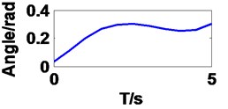
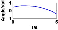
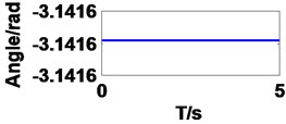
It can be seen in Fig. 4 that the curves of first three angles are correspond to set value in forward kinematics, but they are different to last three angles resulting from multiple solutions.
Fig. 4Joint angles of the robot manipulator
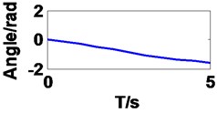
a) Joint 1
b) Joint 2
c) Joint 3
d) Joint 4
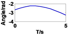
e) Joint 5
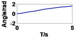
f) Joint 6
2.3. Prediction workspace and experimental validation
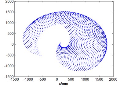
The workspace of robot manipulator becomes a primary performance parameter in addition to its speed, accuracy and weight. The workspace of a robot, also termed as its work envelope, actually expresses a robot’s ability to reach specific area. Given the information about range of motion of joints of a robot and length of its links, workspace can be determined [15]. The robot manipulator workspace has been found mathematically based on the forward kinematics. Fig. 5 illustrates the robot workspace in different coordinates respectively. As shown in Fig. 5(b), the gripper has a manipulation ability inside a circular radius of 1742 mm. Ranges of motion constraints in the body joint restricts the robot functionality in the region in Fig. 5(c) and (d).
The position and orientation was conducted by experimental operation in the minimum limit position. The different gestures are shown in Fig. 6. Therefore, the predict workspace is reasonable and feasible.
Fig. 5Prediction of robot working space
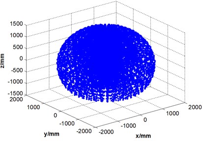
a) 3D in space
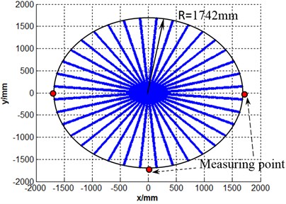
b) plane of projection
c) cross section
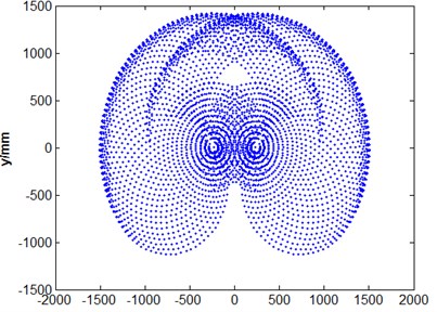
d) cross section
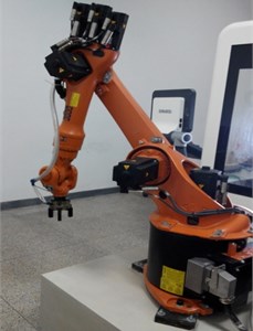
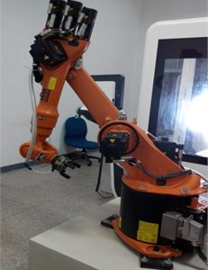
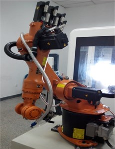
Fig. 6Robot’s state of motion at the limit position
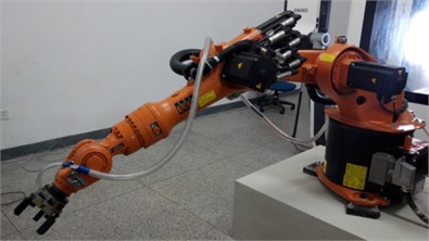
a) Gesture 1
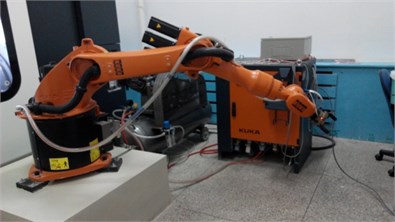
b) Gesture 2
c) Gesture 3
d) Gesture 4
e) Gesture 5
3. Dynamic performance analysis of robot manipulator
3.1. Exciting vibration simulation
The flexible multi-body model is used to simulate the dynamic behavior of robot manipulator. In order to get dynamic performance of robot exactly, the simulation method is the integration of large machine movements under consideration of small deformations in the structural components. The model of rigid-flexible coupling system of robot manipulator is shown in Fig. 7, and the color change shows size of stress change in motion process.
Fig. 7The dynamic simulation process of flexible multi-bodies
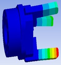
a) Flexible-gripper
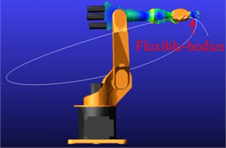
b) Initial point of motion
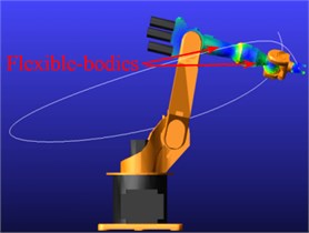
c) Final point of motion
The excitation model will be built base on rigid- flexible coupling system. There are three basic building blocks in vibration in Fig. 8: Input channels, Output channels, and Actuators. Actuators are that vibrates or drive the system in the frequency domain. The actuators ‘act’ at the input channels you specify. Input channels are that defines location and direction of vibratory input. They accept actuators as sources of vibratory input and are used to plot. Output channels are that measure vibratory response.
Fig. 8Vibration model of robot manipulator

In the end point of finger in gripper is loaded an amplitude of 100 N (along the axis direction) excitation signal, the initial phase of 0, and by rapid sine sweep method for vibration analysis. The response output is mainly along the and space synthesis direction of displacement response, comprising frequency response of mechanism analysis diagram. The amplitude frequency response and phase frequency response is shown in Fig. 9.
Table 2Modal parameters of first four orders
Modal order | Nature frequency | Damping ratio | Real part | Imaginary part |
1 | 128.741 | 0.0190184 | –2.44846 | +/–128.718 |
2 | 140.488 | 0.01943 | –2.72967 | +/–140.461 |
3 | 216.974 | 0.999824 | –28692.3 | +/–538.832 |
4 | 603.576 | 0.0464053 | –28.0091 | +/–602.926 |
It can be noticed in Fig. 9 that the maximum response of the end of the robot hand in direction is in 128 Hz frequency, the maximum displacement response is 3.34E-005 mm; the maximum response in direction is in a frequency of 128 Hz, the maximum displacement response is 7.0E-007 mm. The modal parameters of first four orders are shown in Table 2.
Fig. 9Transfer function of gripper
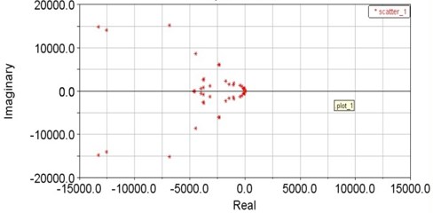
a) Modal characteristic roots
b) Magnitude and phase frequency response curves in and
3.2. Experimental validation
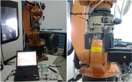
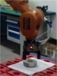
Experimental modal testing system is mainly composed of excitation system, signal collection system, data acquisition and analysis record system. There are some equipment as shown in Fig. 10: 1) modal testing and analysis software Cut/Pro; 2) USB Carrier I/O-9233; Accelerometer sensor 8778a500 (Sensitivity 10.00 mV/g); Hammer type (B&K8206-002) 9722a500 (Sensitivity 10.00 mV/g); Sampling Rate (Hz): 50000; Frequency Range (Hz): 50-5000; Transfer functions: Displacement-Force.
Fig. 10Modal test of 6-DOF industrial robot gripper
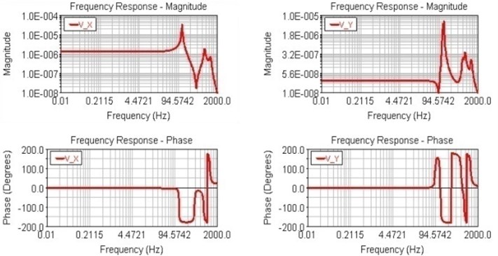
The frequency response functions (real part and imagine part) of finger point are measured in and direction, as shown in Fig. 11. It can be seen that the maximum displacement response and phase response of the mutation both occurred in the 130 Hz frequency, displacement response 2.8E-006 mm. Therefore, the natural frequency of prediction is match with experimental measuring values. The dynamic errors will be provided to motion control system to improve grasping precision.
Fig. 11The FRF of gripper in x direction
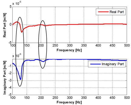
Fig. 12Controller architecture and Bus system of robot manipulator
a) Controller architecture of gripper
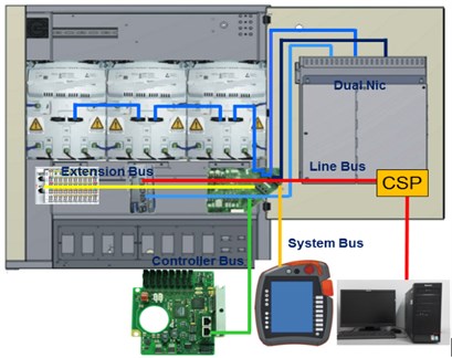
b) Architecture of Bus systems
4. Motion control and grasping process of robot manipulator
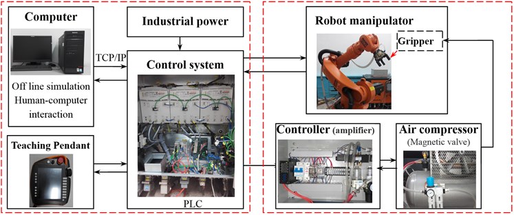
4.1. The control system architecture of manipulator
Controller architecture and Bus system of robot manipulator are shown in Fig. 12. The off line program is edited and simulated in computer, which is send to control system through internet. At the same time, control program is also edited in teaching pendant to control robot manipulator simply. Controller of gripper is independent controller unit, which is conducted to open/close finger (air cylinder) motion in gripper by air compressor (Magnetic valve).
There are some softwares in computer as follows:
• HMI-Human Machine Interface: Visualizing, operating and monitoring: User interface are created quickly and efficiently.
• OPC Server-Software interface for data communication: OPC-Object Linking and Embedding for process control. Exchange (Read and Write) of robot variables between OPC-Client and OPC-Server. Communication can be established inside also to external devices using Ethernet (TCP/IP).
• Workvisual/Visual Process – the offline programming tool integrated into WorkVisual, which is verified to improve the efficiency and quality.
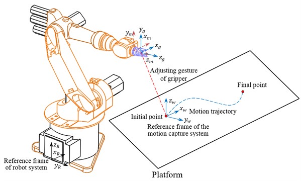
4.2. Implementation of grasping process
The base coordinate is reference markers of the motion capture system (, , ), which can be used to establish a reference coordinate system. The end coordinate of robot (, , ), and coordinate of gripper (, , ) are transformed from base by these markers. The reference position and orientation of motion capture system is obtained based on the gripper and workpiece. The trajectory control of gripper is shown in Fig. 13.
Fig. 13Trajectory control of gripper
An object has been placed at a known position and orientation. With this known information from a user, the coordinate and gesture of gripper is reordered. The grasping progress program codes are as following:
PTP Home Vel = 30 % DEFAULT
Loop
PTP P2 Vel = 30 % PDAT2 Tool[1] Base[0]
OUT 1’Ausgang’ State=FALSE
OUT2’’ State = TRUE
PTP P3 Vel = 30 % PDAT3 Tool[1] Base[0]
PTP P1 Vel = 30 % PDAT1 Tool[1] Base[0]
OUT 1’Ausgang’ State= TRUE
OUT2’’ State = FALSE
….
PTP P3 Vel = 30 % PDAT7 Tool[1] Base[0]
PTP HOME Vel = 30 % PDAT6
End loop
The ‘Waiting grasping’ position and orientation is illustrated in Fig. 14(a). The robot moves as per computed joint angles based on the object coordinate. After reaching the target location, the gripper of the robot closes ultimately grasping the object. Sequence of pick-up of the object is shown in Fig. 14(b). The robot then moves (Fig. 14(c)) toward destination point, whose coordinates have also been taught by the user. The destination point should also lie inside the operational workspace of the robot. After reaching that location, the robot drops the object (Fig. 14(d)) and then finds its way back to the home position.
Fig. 14The grasping process of robot manipulator
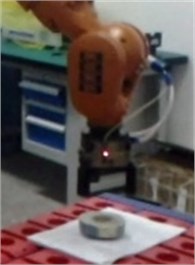
a) Moving from ‘Home’ position to the object
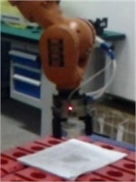
b) Grasping the object
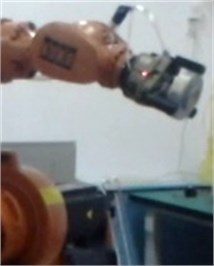
c) Moving to destination position
d) Moving back to ‘Home’ position
5. Conclusions
The workspace of manipulator with gripper is predicted based on kinematical model, which is validated by using experimental measuring. The model of the robot has also provided correct joint angles to move the gripper to any position and orientation with its workspace.
The frequency response property of robot gripper is obtained by flexible multi-body system and was validated by comparing simulation and modal test results. It can be noticed that the simulated results mach exactly with that of experimental measuring.
The control system architecture was given and the grasping process was conducted by gripper based on motion trajectory control in the workspace. The robot gripper achieves position and orientation precision.
The position precision and repeatability precision on trajectory will be measured by using measurement unit in future. In addition, the influence of dynamic performance on the motion precision and grasping precision will be researched detail next step.
References
-
Craig J. J. Introduction to Robotics: Mechanics and Control. 3rd Edition. Prentice Hall, Upper Saddle River, N.J., USA, 2005.
-
Mitsuhiro Hayashibe Robotic surgery setup simulation with the integration of invers-kinematics computation and medical imaging. Computer Methods and Programs in Biomedicine, Vol. 83, 2006, p. 63-72.
-
Lamrechts Paul Trajectory Planning and Feed Forward Design for Electromechanical Motion Systems, Version 2. Report Nr. DCT 2003-04, p. 13-22.
-
GarciaVallejo D., Sugiyama H., Shabana A. A. Finite element analysis of the geometric stiffening effect. Part 1: a correction in the floating frame of referenceof formulation. Multi-body Dynamics, Vol. 219, 2005, p. 187-202.
-
Sugiyamaa H., Gerstmayrb J., Shabana A. A. Deformation modes in the finite element absolute nodal coordinate formulation. Jounal of Sound and Vibration, Vol. 298, 2006, p. 1129-1149.
-
GarciaVallejo D., Sugiyama H., Shabana A. A. Finite element analysis of the geometric stiffening effect. Part 2: nonlinear elasticity. Multi-body Dynamics, Vol. 219, 2005, p. 203-211.
-
Kris K., Imme E.-U., William Singhose Locally liearized dynamic analysis of parallel manipulators and application of input shaping to reduce vibrations. Journal of Mechanical Design, Vol. 126, Issue 1, 2004, p. 156-168.
-
Bayro-Corrochano Eduardo Differential and inverse kinematics of robot devices using conformal geometric algebra. Robotica, Vol. 25, 2007, p. 43-61.
-
Zaeh M., Siedl D. A new method for simulation of machining performance by integrating, finite element and multi-body simulation for machine tools. Annals of the CIRP, Vol. 56, Issue 1, 2007, p. 383-386.
-
Altintas Y., Brecher C., Weck M., Witt S. Virtual machine tool. Annals of CIRP, Vol. 54, 2005, p. 651-667.
-
Andreas T. P., Lee J. S., Han J. H. Ornithopter flight simulation based on flexible multi-body dynamics. Journal of Bionic Engineering, Vol. 7, 2010, p. 102-111.
-
Grecoa M., Codab H. B. Positional FEM formulation for flexible multi-bodydynamic analysis. Journal of Sound and Vibration, Vol. 290, 2006, p. 1141-1174.
-
Lin H., Chen C. A hybrid control policy of robot arm motion for assistive robots. Proceedings of the IEEE International Conference on Information and Automation, Shenzhen, China, 2011, p. 163-168.
-
Mohamed Z. Techniques for vibration control of a flexible robot manipulator. Robotica, Vol. 4, 2006, p. 499-511.
-
Jamshed Iabal, Raza ul Islam, Hamza Khan Modeling and analysis of a 6-DOF robotic arm manipulator. Canadian Journal on Electrical Electronics Engineering, Vol. 3, Issue 6, 2012, p. 300-306.
-
Subudhi B., Morris A. S. Soft computing methods applied to the control of a flexible robot manipulator. Applied Soft Computing Journal, Vol. 9, Issue 1, 2009, p. 149-158.
-
Kucuk S., Bingul Z. An off-line robot simulation tool box. Computer Applications in Engineering Education, Vol. 18, Issue 1, 2010, p. 41-52.
-
Rubio Francisco, Valero Francisco, Sunyer Joseph Optimal time trajectories for industrial robots with torque, power, jerk and energy consumed constraints. Industrial Robot, Vol. 39, Issue 1, 2012, p. 92-100.
-
Tan G. Z., Wang Y. C. Theoretical and experimental research on time-optimal trajectory planning and control of industrial robots. Control Theory and Applications, Vol. 20, Issue 2, 2003, p. 185-192.
-
Attia Hazem Ali Dynamic modeling of a serial robot manipulator using point and joint coordinates. Advances in Modeling and Analysis, Vol. 7, 2003, p. 11-25.
-
Braunl Thomas Fault-tolerant robot programming through simulation with realistic sensor models. International Journal of Advanced Robotic Systems, Vol. 2, 2006, p. 99-106.
About this article

This work was supported by (National Natural Science Foundation of China) NSFC (51105072) and (51475087), supported by Fundamental Research Funds for the Central Universities (N130403010) and Education Department of Liaoning Province Key Laboratory Project (LZ2014016).
