Abstract
It is very important to predict the acoustic radiation of vehicle body for the control of interior noise. Firstly, the kinetic equations of coupled acoustic-structural finite element method are explained and the numerical analytical methods of noise transfer function and acoustic panel participation are further obtained. Then the coupled acoustic-structural finite element model of body in white and passenger compartment cavity of a minicar is established and verified by modal test. The passive side of engine mounting points are chosen as the excitation points, and driver’s right ear is the output point of sound pressure response. The noise transfer function is calculated and the critical frequency of vehicle interior noise is obtained. The acoustic panel participation analysis of vehicle roof and floor are conducted, and the key acoustic panels are identified. In order to reduce the noise of critical frequency, the measures, pasting damping material and welding beam, are adopted. The results indicate that, compared with the results of structure improvement of modal method, the vehicle interior noise is controlled more effectively by using the acoustic panel participation analytical method.
1. Introduction
Vehicle interior noise, especially the low frequency noise, affects the driving comfort of occupants seriously. If a driver is exposed in low frequency noise environment for a long time, the driver will feel tired which influences driving safety, and thus it is necessary to reduce the low frequency noise. Vehicle interior noise includes two parts, the air-borne noise and the structure-borne noise, and structure-borne noise is the main component of low frequency noise [1]. The essence of structure-borne noise is that the vibrating body panels radiate noise to the cab and cause the sound pressure changed, the changed sound pressure in cab will influence the vibration of panel structure conversely, which is a complex dynamic coupling process.
By now, many investigations have been carried out on coupled acoustic-structural analysis and noise radiation. The concept of acoustic-structural coupling was put forward by Rayleigh in his book “The Theory of Sound” (1877) firstly, however, in the vehicle research field, the study on interior noise based on coupled acoustic-structural method was first proposed by Smith [2]. In the field of modeling method, Lee [3] proposed a new analytical model which was consisted of double cavities connected by a neck and two mechanical harmonic oscillators. Donders [4] used the “Reduced Beam and Joint Modeling” approach to analyze and optimize the global bending and torsion modes of vehicle body in the concept phase. Refs [5-7] developed a coupled edge-based smoothed and face-based smoothed finite element method to solve 3D acoustic problems. Dhandole [8] updated the acoustic finite element model using pressure response. Maxit [9] investigated the modal interaction between a panel and a heavy fluid cavity. In the field of cavity acoustic analysis, Steffen [10] adopted the numerical method with minimizing the average sound pressure at target points to optimize and passive control of the internal noise. Liang [11] achieved the relationship between panel design parameters with mean quadratic velocity, sound radiation power and system loss factor. Lee [12] conducted topology optimization on structural panels between a two cavities. Refs [13] applied and validated a numerical method for predicting the acoustic and structural NVH of trimmed body components. In the field of acoustic modal participation analysis, Refs [14, 15] analyzed the structural modal participation at critic frequency of noise and identified the main participation of structural modal. Marburg [16] carried out shape optimization of engine compartment to make the first order structure modal frequency maximum. Liu [17] predicted the interior noise of rectangular structure cavity and the intense vibration panels were identified. Citarella [18] combined the FEM and BEM approach to study the modal acoustic transfer vector. Rousounelos [19] constructed a weakly radiating structural modes on the panel by placing a number of constraint masses and stiffeners. In the field of transfer path analysis, Li [20] explored the relationship between the transfer path and the control strategies with a fully coupled vibro-acoustic model. Nejade [21] separated and quantified noise contributions from casings and other plate like components in complex machines. Yan [22] found out the source with dominant contribution and picked up the largest sound quality contribution source from three sources. In the field of acoustic panel participation (APP) analysis, Refs [23, 24] investigated the acoustic panel participation of vehicle floor using numerical calculation method. Kassem [25] presented an energy-density approach to study the noise in the low and medium frequency ranges. Wu [26] calculated the acoustic power flows from individual panels of a vibrating structure and ranked their participations toward the sound pressure level value. In the field of noise testing, Marburg [27] measured structural modal and noise transfer functions of a steel box 1.0×1.1×1.5 m. Misol [28] experimentally studied the different active structural acoustic control concepts for the reduction of interior noise in an automobile passenger compartment. Ulrich [29] examined detection and localization of recorded sounds of approaching target vehicles in the presence of competing noise from a second vehicle. Nopiah [30] identified main sources that contribute to the generation of vibration.
Summarily, existing research works had made many progresses in the field: establishing numerical model, noise simulation analysis and testing, meanwhile, there remain some problems need to be further investigated, especially for the noise analysis and control of passenger compartment cavity. The geometry shape of passenger compartment cavity and body in white (BIW, i.e. a car body’s sheet metal components have been welded together, but before moving parts (doors, hoods, and deck lids as well as fenders), the motor, chassis sub-assemblies, or trim (glass, seats, upholstery, electronics, etc.) have been added), are complex and the total sound pressure in cavity is the superposition of sound pressures which are caused by the vibration of structure panels. The total sound pressure has many peak values affected by vibration amplitude and phase of structure panel, and the sound pressure is distinct for different transfer paths. The noise can’t be reduced effectively if we do not improve the structure of key acoustic panels. In order to carry out acoustic investigation and noise control for the coupled acoustic-structural problem of cavity and BIW, three critical technological problems need to be addressed. The first one is the establishment of simulation model. Because the passenger compartment cavity and BIW have complex geometry shape which make the coupled acoustic-structural model complicated. The second one is obtaining the critical frequency of interior noise. The third one is the identification of key acoustic panels. The total sound pressure is affected by the vibration amplitude and phase of structure panels, and it is important to pick up the key acoustic panels from the structure panels of BIW before carrying out structural improvement.
In view of this, the paper is aimed to investigate the noise control of BIW and passenger compartment cavity coupling system by using the APP analysis method. The three critical technological problems mentioned above are solved. The simulation model of BIW and cavity is built and verified by free modal experiment. The NTF analysis and APP analysis are carried out. At last, the improved method of structure is put forward for a minicar BIW.
2. The theory of acoustic panel participation
2.1. Weakly coupled structure acoustic method
Passenger compartment cavity and BIW is a typical weakly coupled acoustic-structural system [31]. The control equations for coupling system can be got by integrating the control equations of structure and acoustic, which can be written as [24]:
In which, and are the displacement of structural node and pressure of acoustic node, respectively. , and are the mass matrix of structure, air cavity and interface matrix of the structure acoustic, respectively. and represent damping matrix of structure and air cavity, respectively. and represent the stiffness matrix of structure and air cavity, respectively. and are the external excitation load imposing on structure and air cavity, respectively.
2.2. The theory of noise transfer function
The definition of NTF is that an external excitation imposes on structure and computes the acoustic frequency response of the point we interested, which is an important reference to evaluate the low frequency noise and acoustic sensitivity. Make the following assumptions before calculating the NTF [9]: The air is a continuous ideal fluid, heat exchange caused by temperature difference is not considered during sound transmission in air, and the vibration of BIW is small which satisfy the linear relationship between the structure vibration and acoustic pressure. A unit sine excitation imposes on structure, where and is the angular frequency and plural unit, respectively. Set the steady-state responses of Eq. (1) are and . Substituting these relations into Eq. (1), we get the equation in frequency domain as:
According to Eq. (2), the acoustic pressure response of arbitrary point in cavity can be obtained:
The Eq. (3) is the NTF, and expresses it in the form of sound pressure levels () which is shown in Eq. (4), where the reference sound pressure 2×10⁻⁵ Pa, and the unit of is dB:
2.3. The method of acoustic panel participation
For different panels, the value of APP is different and can be classified into positive, negative and neutral contribution [24]. Assuming that the FE model of structure and air cavity have been established and the vibration displacement of the node of the panel is , according to the relationship between normal vibration displacement of panel structure and sound pressure response (see Eq. (3)), the acoustic pressure caused by node vibration is calculated:
The acoustic pressure caused by panel is obtained by summing the sound pressure vectors caused by the vibration of nodes on panel , which can be expressed as:
The total sound pressure is the sum of sound pressures caused by the vibration of panels surround the cavity and can be written as:
The APP is applied to evaluate the acoustic participation of panel which is illustrated in Eq. (8). The physical meaning of APP is the projection of sound pressure caused by panel vibration. Eq. (9) is the acoustic panel participation factors (APP factors) of panel :
Fig. 1The relationship between total sound pressure and acoustic panel participation
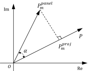
The relationship between total sound pressure and acoustic panel participation is shown in Fig. 1, in which, is the angle between the sound pressure caused by panel vibration and total sound pressure. If 90°,90° or 90°, the vibration of panel are positive, neutral or negative contribution to total sound pressure, and with increasing the vibration displacement of panel , the total sound pressure increases, keeps unchanged or reduces, respectively.
From the above analysis, it can be concluded that it’s crucial to identify the key acoustic panel before modifying panel structure for noise control. The measures that increase the vibration of positive acoustic contribution panel or decrease the vibration of negative acoustic contribution panel can be used to reduce the noise of target point. However, the traditional control method is to reduce the vibration of panel structures which vibrate strongly, and thus the vibration phase of panel structures are not considered.
3. Acoustic-structural coupled model of Minicar BIW
The minicar has the advantage that energy consumption less, economy and broad market demanding, while there are some problems for a minicar BIW, such as thinner sheet metal, simple measures to reduce vibration and noise. Thus a minicar BIW and passenger compartment cavity which is a typical weakly coupled acoustic-structural system are chosen as the research objective to investigate the APP quantitatively and control the interior noise. A critical technological problems presented above, i.e. construction of coupled model for the complex structure of BIW and cavity, is solved in this section. The FE model of BIW is meshed from geometry model directly, and the FE model of cavity is meshed from the enveloping solid between inside surfaces of vehicle body and outside surfaces of seats. To guarantee the accuracy of simulation model, a free modal test is conducted.
3.1. FE model of coupling system
The pre-processing of FE model is realized in Hyperworks software, and the coupled model is computed in MSC.Nastran software.
3.1.1. FE model of BIW
The BIW is composed of sheet metal parts mostly, and mesh them with shell element of four nodes or three nodes. To avoid the model stiffness too large to inaccurate, the number of three-node shell elements is restricted and not more than 3 % in the FE model. The material of BIW is ordinary steel (Young modulus 2.1×10⁵ MPa, mass density 7.8×10³ kg/m3, Poisson ratio 0.3 and damping unconsidered). The spot welding is used to connect the structure panels and simulated with the element ACM2 (i.e. six-sided solid element and interpolation constraint element). The adhesive connection (Young modulus 50 MPa, mass density 1.2×10³ kg/m3, Poisson ratio 0.49 and damping coefficient 0.1) is applied between front windscreen and frame. The element number of BIW is 727340 and the number of three-node shell element is 8718. The AUTOSPC (details see the help documentation of MSC.Nastran software) is used as the boundary conditions of FE model of BIW.
3.1.2. FE model of passenger compartment cavity
To guarantee the calculation precision of finite element method for acoustic analysis, at least six elements are contained in an acoustic wavelength. The wave equation of sound is , where , and are the wavelength of acoustic, acoustic velocity and frequency, respectively [32]. The finite element method has a higher accuracy of acoustic analysis in low frequency range, so the upper limit of calculating frequency is set to 200 Hz [23]. At 15 °C in air, the velocity of acoustic is 340 m/s, and thus the mesh size of element is 0.283 m. The cavity between vehicle body structure and seats is filled with air (mass density 1.2 kg/m3, celerity 340 m/s, and damping unconsidered) and modeled with four-sided solid element. The element number of cavity is 78098 and average size of mesh is 0.1 m. Couple the FE model of acoustic and BIW, and solve the coupled model by using the modal superposition method. To reduce the truncation error of modal superposition method, the end frequency of modal method is at least twice of the upper limit of calculating frequency [18], which is 400 Hz. The structure vibration of BIW is set as boundary conditions during the calculating of NTF and APP.
3.2. Test verification for simulation model
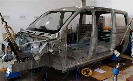
To verify the reliability of simulation mode, the free modal testing of BIW is carried out which can be seen in Fig. 2. For the complexity of BIW structure, the data of many points need to be tested. The measurement method of multi-point excitation and multi-point output is carried out, and the vibration test data of 102 points are got.
Fig. 2Free modal testing of BIW structure
The modal results of simulation and experiment are shown in Table 1. It can be concluded that the modal vibration shapes agree well and relative errors of frequency are less than 5 % mostly, which indicate that the dynamic characteristic of BIW can be predicted well by the FE model.
Table 1Comparison of modal results of simulation and experimental
Frequency calculated / Hz | Frequency tested / Hz | Relative error / % | Description of modal |
27.1 | 26.1 | 3.83 | Torsional mode of tail gate |
29.8 | 27.2 | 9.56 | Local mode of rear roof |
38.4 | 38.3 | 0.26 | 1st torsional mode of BIW |
42.3 | 42.7 | –0.94 | 2nd local mode of roof |
46.7 | 45.9 | 1.74 | Breathing mode of BIW |
53.5 | 51.4 | 4.08 | 1st bending mode of BIW |
59.9 | 58.2 | 2.92 | Mode of roof and floor |
4. Results and discussion
Based on the simulation model verified above, the NTF analysis, APP analysis and panel structure improved method will be investigated in this section orderly.
4.1. Analysis of noise transfer function
A unit sine excitation of direction imposes on the passive side of engine mounts respectively, and calculate the acoustic frequency response of driver’s right ear, which is the NTF from direction of engine mounts to the driver’s right ear, as shown in Fig. 3. Where nodes 2001, 2002 and 2003 are the left, right and rear mount of engine respectively, node 9001 (0.223 m, 2.095 m, 0.960 m) is the position of driver’s right ear. The load cases are listed in Table 2.
Fig. 3Computational model of noise transfer function
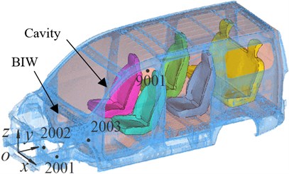
Fig. 4Noise transfer function of each subcase
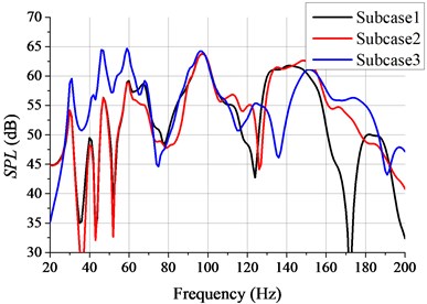
Table 2The load description of each subcase
Case No. | Load position (m) | Excitation (N) | Excitation frequency (Hz) |
Subcase 1 | 2001 (0.162, 0.567, –0.077) | 20-200 | |
Subcase 2 | 2002 (–0.165, 0.567, –0.074) | 20-200 | |
Subcase 3 | 2003 (–0.031, 1.242, –0.035) | 20-200 |
The NTFs of three paths are shown in Fig. 4. It can be seen from Fig. 4 that the values of (i.e. interior noise) are different for different transfer paths and the value of of path 3 is bigger especially at the low frequency band, the reason for this is that the transfer path from rear mount of engine (node 2003) to driver’s right ear (node 9001) is shorter. The NTFs of path 1 and path 2 are similar, because the BIW and cavity, excitation of subcase 1 and subcase 2 are symmetric about plane -- and the output point of sound pressure response (node 9001) is close to plane --. It is obvious that the NTFs have many peak noises in frequency band 20-200 Hz, and the critical frequencies are 31 Hz, 47 Hz, 59 Hz, 97 Hz and 148 Hz successively. Because the BIW is composed of many sheet metals and connected by welding, which have dense structure modes. If excitation frequency is close to a natural frequency of BIW structure, the vibration of BIW structure increases, which is easy to cause structural resonance and radiate noise seriously.
From the above analysis, it can be found that the interior noises are different for different transfer paths, and short transfer path has big interior noise. There are many critical frequencies in the excitation frequency band.
4.2. Analysis of acoustic panel participation
According to the NTFs analysis above, the values of are larger at frequency point 59 and 97 Hz, and the critical frequency 59 Hz which is a lower frequency is chosen to conduct APP analysis in this part. The values of driver’s right ear are 58.96 dB for subcase 1 and 2, 64.4 dB for subcase 3. The size, position and orientation of structure panels effect the noise in cavity, especially the large panels, such as the roof, floor, front dashboard and front windshield of BIW. The roof and floor are chosen as the research object of APP. The panel dividing methods of roof and floor are shown in Fig. 5. The roof is divided into 20 panels and numbered from P1 to P20, and the floor is divided into 28 panels and numbered from P21 to P48 (see Fig. 5). The position of beams and mounting holes are considered during dividing.
The APP analysis of roof and floor is carried out at frequency point 59 Hz, and the results of APP of roof at subcase 1 are shown in Table 3. It can be found from Table 3 that the values of panel sound pressure and acoustic panel participation are different, the values of of P1-P4 are bigger, the reason for this is that these panels are close to the output point of sound pressure response (node 9001). The value of can be positive, negative or zero which is determined by the angle , which agrees well with the theory of Eq. (8). The value of driver’s right ear is 58.96 dB (59 Hz) at subcase 1 (see Fig. 4), according to Eq. (4), the effective value of total sound pressure (0.707 ) is 1.774×10⁻² Pa. Substituting the total sound pressure 2.51×10⁻² Pa into Eq. (9), the APP factors at 59 Hz are obtained which are given in Table 3. The value of P15 is 6.41×10⁻⁴ Pa while the value of this panel is small and negative, because is bigger than and close to 90°. From the above analysis, it can be concluded that the value of acoustic panel participation is decided by the value of panel sound pressure and the angle .
Fig. 5Structure dividing methods of roof and floor
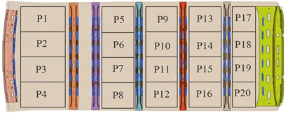
a) Dividing method of vehicle roof
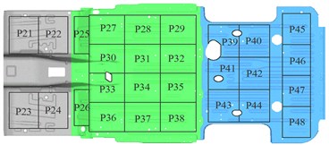
b) Dividing method of vehicle floor
Table 3The results of acoustic panel participation of roof (subcase 1, frequency point 59 Hz)
Panel No. | (10-4 Pa) | (degree) | (10-4 Pa) | (%) | Panel No. | (10-4 Pa) | (degree) | (10-4 Pa) | (%) |
1 | 11.70 | –23.13 | 10.80 | 4.29 | 12 | 2.86 | 152.52 | –2.54 | –1.01 |
2 | 13.00 | –15.27 | 12.50 | 4.99 | 13 | 2.65 | 14.87 | 2.56 | 1.02 |
3 | 10.70 | –6.84 | 10.60 | 4.22 | 14 | 3.22 | 72.72 | 0.96 | 0.38 |
4 | 6.88 | –1.07 | 6.88 | 2.74 | 15 | 6.41 | 111.77 | –2.38 | –0.95 |
5 | 3.98 | –162.51 | –3.80 | –1.51 | 16 | 5.00 | 120.56 | –2.54 | –1.01 |
6 | 4.89 | –149.28 | –4.20 | –1.67 | 17 | 4.17 | 7.82 | 4.13 | 1.65 |
7 | 3.79 | –104.27 | –0.93 | –0.37 | 18 | 8.48 | 21.60 | 7.88 | 3.14 |
8 | 1.97 | –63.00 | 0.89 | 0.36 | 19 | 8.62 | 30.20 | 7.45 | 2.97 |
10 | 1.86 | –140.35 | –1.43 | –0.57 | 20 | 4.13 | 38.43 | 3.24 | 1.29 |
11 | 3.58 | 178.66 | –3.58 | –1.43 |
Fig. 6Results of acoustic panel participation of roof and floor (three subcases, frequency 59 Hz)
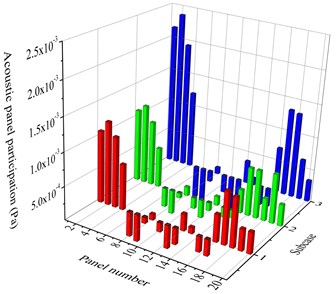
a) Acoustic panel participation of roof
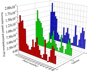
b) Acoustic panel participation of floor
Fig. 6 shows the results of APP of roof and floor (three subcases, frequency 59 Hz). It can be seen from Fig. 6 that, the values of APP are different for different panels at the same subcase, and the values of APP are also different for same panel at the different subcases. The values of APP at subcase 1 and 2 are similar, because the BIW and cavity, panel dividing, excitation of subcase 1 and subcase2 are almost symmetric about plane -- and output point of sound pressure response (node 9001) is close to plane --. In terms of vehicle roof (see Fig. 6(a)), the APP values of P1-P4 and P17-P20 (i.e. the front and rear of roof) are big and positive, and according to the theory above the measure of reducing vibration of these panels will be effective to decrease the noise at 59 Hz. The APP values of P5, P6, P10, P11, P12, P15 and P16 are big and negative, and increasing the vibration of these panels will be feasible to control noise. For vehicle floor (see Fig. 6(b)), the APP values of floor are almost all positive and the results of P21-P26, P32, P34, P35, P41, P45-P47 are big, thus the measure of reducing vibration of these panels will decrease the noise at 59 Hz remarkably.
Using the APP analysis method, the acoustic participation property of panels are classified, the values are ranked as well as the key acoustic panels are identified from the complex structure of BIW. According to the above analysis, it can be found that the values of APP are different for different panels and the property of APP is determined by the angle . If is smaller, bigger than or close to 90°, the APP values of corresponding panels will be positive, negative or zero.
4.3. Improvement of panel structure
There are three methods to control noise [33]: (1) Reduce the vibration or noise of excitation source; (2) Cut or attenuate the vibration transfer path between excitation source and noise receptor; (3) Protect the noise receptor. The second method, attenuating the vibration transfer path, is chosen to control the noise in cavity in this paper.
Fig. 7Structure improvement method of Opt_1
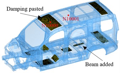
Fig. 8The 14th mode of BIW
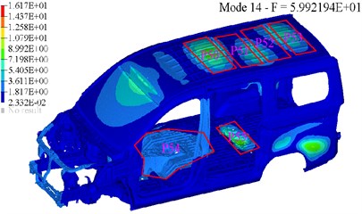
The way to reduce the vibration of the main positive acoustic participation panels is adopted to control noise at 59 Hz. Because increasing the vibration of negative acoustic participation panels need to reduce the thickness of corresponding panels, and thus the thickness of roof and floor are not unified which is bad for once stamping forming of sheet metal. The damping layer (Young modulus 5000 MPa, mass density 1.4×10³ kg/m3, Poisson ratio 0.45 and damping ratio 0.3) is pasted on P1-P4, P17-P20, P21-P26, P34, P41, P45-P47 and the thickness of it is 5 mm. A “U” section beam (length 420 mm, width 45 mm, high 35 mm and thickness 1.2 mm) is welded on the floor to reduce the vibration of P32, P35 and P41 (see Fig. 7), and the structure improvement based on APP method is denoted by Opt_1. The 14th structure mode of BIW (mode frequency 59.9 Hz) is nearest to critical frequency 59 Hz (see Fig. 8), and the large panels (roof, floor and left side wall of BIW) vibrate strongly which is easy to cause a big sound pressure in cavity. Thus, compared with other structure modes closing to 59 Hz, the way of pasting damping layer according to the 14th structure mode of BIW will control the sound pressure more effectively. The vibration of P50 and P51 (i.e. panels P5-P12 in Fig. 7) is larger while these panels are negative acoustic participation (see Table 3 and Fig. 6(a)), hence, the positions of strong vibration in mode are not always large acoustic participation which agrees with the above panel acoustic theory perfectly. The same damping layer is pasted on P50, P51, P52, P53, P54, and the beam of Opt_1 is welded on P55 to reduce the panel vibration. The structure improvement based on modal method is denoted by Opt_2 (see Fig. 8).
The NTFs of subcase 2 and subcase 3 are shown in Fig. 9 and Fig. 10, in which the original BIW is denoted by base mode (BM). The value of at 59 Hz decreases after panel structure improved, and the phenomenon is more obviously in subcase 2. It can be seen from Fig. 9 that, comparing the results of Opt_1 and BM, the peak value of around 59 Hz decreases from 58.91 dB to 52.14 dB (58 Hz), 6.77 dB reduced totally, however, the value of 47 Hz small increases. Comparing with the results of BM, the value of Opt_2 around 59 Hz decreases from 58.91 dB to 53.55 dB (59 Hz), 5.36 dB reduced totally. It can be found from Fig. 10 that, comparing with the results of BM, the value of Opt_1 around 59 Hz reduces from 64.61 dB to 60.48 dB (57 Hz), 4.13 dB reduced totally, while for Opt_2, the value of 59 Hz decreases from 64.61 dB to 61.07 dB (57 Hz), 3.54 dB reduced totally. The noise value at critic frequency reduces obviously after panel structures improvement, while the noise increases slightly at some frequency points. Compared with the results of Opt_2, the noise value of Opt_1 reduces more effectively which means that the panel structures improvement based on APP method control noise better. The mass of damping material used in Opt_1 is 10.5 kg and 11.2 kg in Opt_2, thus the structures improvement of Opt_1 control noise better with less damping material used. According to the above analysis, it can be found that the key acoustic panels are identified by using the panel acoustic analysis which makes the improving of panel structural more targeted, and this structural improvement method not only controls the interior noise better but also uses less damping material.
Fig. 9The noise transfer function of subcase 2
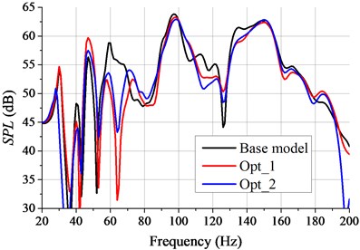
Fig. 10The noise transfer function of subcase 3
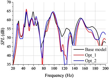
Fig. 11The VTF of node 10000 at subcase 3
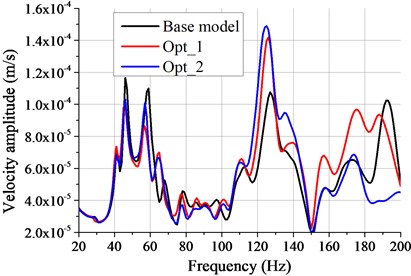
Fig. 12Acoustic panel participation of P2 (Subcase 3)
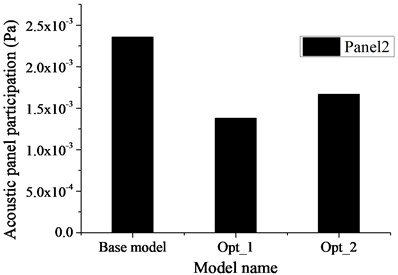
Fig. 11 is the velocity transfer function (VTF) of node 10000 where the panel around is positive acoustic participation. The definition of VTF is that unit sine excitation imposes on structure and solve the velocity response of target point. It can be seen from Fig. 11 that, compared with the results of BM, the VTF of Opt_2 around 59 Hz decreases from 1.09×10⁻⁴ m/s to 9.93×10⁻⁵ m/s (57 Hz), 8.9 % reduce totally. The reason for this is that the stiffness of BIW increases slightly after pasting damping material and welding beam, and thus the vibration of node 10000 reduces. The VTF value of Opt_1 around 59 Hz decreases from 1.09×10⁻⁴ m/s to 8.51×10⁻⁵ m/s (57 Hz), 21.9 % reduced totally. Because the damping layer is pasted on panels P1-P4 specially, leading to the vibration of panels P1-P4 reduced as well as the vibration of node 10000 reduced. The APP of panel 2 at subcase 3 is shown in Fig. 12, where the node 10000 is on this panel. It can be found from Fig. 12 that the property of APP of each case keeps unchanged, while the value of it changes, and the APP value of Opt_1 decreases more. Because the APP value of P2 is positive (see Fig. 6(a) and Fig. 12), and the damping layer pasted on P2 of Opt_1 (see Fig. 7) which reduces the vibration of panel2 targeted decreases the acoustic participation of panel2. It can be known from Fig.11 and 12 that pasting damping material on positive acoustic panels reduces the vibration of these panels, which lead to the APP value decreased, the property of APP unchanged and the noise at critic frequency decreased at last. This agrees well with the theory of Section 2.3.
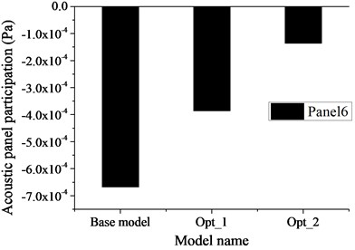
Fig. 13 shows the VTF of node 10001 where the panel around is negative acoustic participation. Focusing on the results in Fig. 13, the VTF value of Opt_2 around 59 Hz decreases from 2.92×10⁻⁴ m/s to 1.09×10⁻⁴ m/s (57 Hz), 62.7 % reduce totally, because the damping layer pasted on P50 (see Fig. 8) lead to the vibration of node 10001 reduced seriously. Compared with the results of BM, the VTF value of Opt_1 around 59 Hz decreases from 2.92×10⁻⁴ m/s to 2.11×10⁻⁴ m/s (57 Hz), 27.7 % reduce totally. The reason for this is that the stiffness of BIW increases after pasting damping material and welding beam. The APP of panel 6 at subcase 3 is shown in Fig. 14, where the node 10001 is on this panel. It can be found from Fig. 14 that the property of APP of each case keeps negative, while the value of it changes and the APP value of Opt_2 decreases more. The reason for this is that pasting damping material on P6 of Opt_2 (see Fig. 5(a) and 8) which reduces the vibration of P6 targeted decreases the value of the negative acoustic participation. It can be known from Fig. 10, 13 and 14 that, comparing the results of Opt_1 and Opt_2, pasting damping material on negative participation panels reduces the vibration of these panels, which lead to the APP value decreased, the property of APP unchanged and the noise at critic frequency increased at last. This also agrees well with the theory of Section 2.3.
Fig. 13The VTF of node 10001 at subcase 3
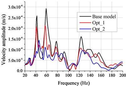
Fig. 14Acoustic panel participation of P6 (Subcase 3)
5. Conclusion
In this paper, the interior noise of a minicar BIW is investigated and controlled by using the acoustic panel participation method. The NTF is employed to describe the influence of transfer paths on interior noise and the critic frequencies are obtained. Using the APP method, the acoustic participation analysis of vehicle roof and floor at critic frequency is carried out and the key acoustic panels are identified. Based on the above analysis, the following conclusions could be derived:
1) The NTF analysis from passive side of engine mountings to driver's right ear are conducted. The results show that NTFs have many peak noises due to the dense modes of BIW structure and critical frequencies are obtained. The interior noise is different for different transfer paths and short transfer path has a big noise value. For the symmetric transfer paths and symmetric coupled acoustic-structural system, the NTFs are similar.
2) For different panels, the APPs are distinct, which is affected by the size and space position of panels. The value of APP is influenced by the amplitude and phase of panel vibration, and positive or negative participation is determined by angle . If is smaller, bigger than or close to 90°, the APP value of corresponding panel will be positive, negative or zero.
3) Pasting damping material on positive acoustic panels reduces the vibration of these panels obviously, which lead to the APP value decreased, the property of APP unchanged and the noise at critic frequency decreased at last. Pasting damping material on negative acoustic panels reduces the vibration of these panels enormously, which lead to the APP value decreased and the property of APP unchanged, while the noise at critic frequency increases at last.
4) Using the acoustic panel participation method, the key acoustic panels are identified which makes panel structural improvement more targeted. Compared with panel improvement by using modal method, the structural improvement according to APP method not only control the interior noise effectively but also use less damping material.
References
-
Kulah S., Aridogan U., Basdogan I. Investigation of an Active Structural Acoustic Control System on a Complex 3D Structure. Springer, New York, 2013.
-
Smith D. L. Acoustic Cavity Resonance in an Automobile Passenger Compartment. Internal General Motors Publication, 1975.
-
Lee J. W., Lee J. M. Forced vibro-acoustical analysis for a theoretical model of a passenger compartment with a trunk. Part 1: theoretical part. Journal of Sound and Vibration, Vol. 299, Issues 4-5, 2007, p. 900-917.
-
Donders S., et al. A reduced beam and joint concept modeling approach to optimize global vehicle body dynamics. Finite Elements in Analysis and Design, Vol. 45, Issues 6-7, 2009, p. 439-455.
-
He Z. C., Liu G. R., Zhong Z. H., et al. A coupled edge-/face-based smoothed finite element method for structural-acoustic problems. Applied Acoustics, Vol. 71, Issue 10, 2010, p. 955-964.
-
He Z. C., Liu G. R., Zhong Z. H., et al. Coupled analysis of 3D structural-acoustic problems using the edge-based smoothed finite element method/finite element method. Finite Elements in Analysis and Design, Vol. 46, Issue 12, 2010, p. 1114-1121.
-
He Z. C., Liu G. Y., Zhong Z. H., et al. An ES-FEM for accurate analysis of 3D mid-frequency acoustics using tetrahedron mesh. Computers and Structures, 2012, p. 125-134.
-
Dhandole S., Modak S. V. A constrained optimization based method for acoustic finite element model updating of cavities using pressure response. Applied Mathematical Modelling, Vol. 36, Issue 1, 2012, p. 399-413.
-
Maxit L. Analysis of the modal energy distribution of an excited vibrating panel coupled with a heavy fluid cavity by a dual modal formulation. Journal of Sound and Vibration, Vol. 332, Issue 25, 2013, p. 6703-6724.
-
Marburg S. Developments in structural-acoustic optimization for passive noise control. Archives of Computational Methods in Engineering, Vol. 9, Issue 4, 2002, p. 291-370.
-
Liang X. H., Lin Z. Q., Zhu P. Acoustic analysis of damping structure with response surface method. Applied Acoustics, Vol. 68, Issue 9, 2007, p. 1036-1053.
-
Lee J. W., Kim Y. Y. Optimal distribution of holes in a partition interfacing two cavities for controlling the eigenfrequencies by acoustical topology optimization. Computer Methods in Applied Mechanics and Engineering, Vol. 198, Issues 27-29, 2009, p. 2175-2189.
-
Christopher J., Per W., Peter G. Prediction of NVH behaviour of trimmed body components in the frequency range 100-500 Hz. Applied Acoustics, Vol. 71, Issue 8, 2010, p. 708-721.
-
Kim S. H., Lee J. M., Sung M. H. Structural-acoustic modal coupling analysis and application to noise reduction in a vehicle passenger compartment. Journal of Sound and Vibration, Vol. 225, Issue 5, 1999, p. 989-999.
-
Song C. K., Hwang J. K., Lee J. M., et al. Active vibration control for structural-acoustic coupling system of a 3-D vehicle cabin model. Journal of Sound and Vibration, Vol. 267, Issue 4, 2003, p. 851-865.
-
Marburg S., Hardtke H. J. Shape optimization of a vehicle hat-shelf: Improving acoustic properties for different load cases by maximizing first eigenfrequency. Computers and Structures, Vol. 79, Issues 20-21, 2001, p. 1943-1957.
-
Liu Z. S., Lee H. P., Lu C. Passive and active interior noise control of box structures using the structural intensity method. Applied Acoustics, Vol. 67, Issue 2, 2006, p. 112-134.
-
Citarella R., Federico L., Cicatiello A. Cicatiello. Modal acoustic transfer vector approach in a FEM-BEM vibro-acoustic analysis. Engineering Analysis with Boundary Elements, Vol. 31, Issue 3, 2007, p. 248-258.
-
Rousounelos A., Walsh S. J., Krylov V. V., et al. Optimisation of the structural modes of automotive-type panels using line stiffeners and point masses to achieve weak acoustic radiation. Applied Acoustics, 2015, p. 23-37.
-
Li Y. Y., Cheng L. Active noise control of a mechanically linked double panel system coupled with an acoustic enclosure. Journal of Sound and Vibration, Vol. 297, Issues 3-5, 2006, p. 1068-1074.
-
Nejade A. A prediction method for separating and quantifying noise contributions from casings and other plate like components in complex machines. Journal of Sound and Vibration, Vol. 331, Issue 23, 2012, p. 5028-5039.
-
Yan L., Jiang W. K. Research on the procedure for analyzing the sound quality contribution of sound sources and its application. Applied Acoustics, 2014, p. 75-80.
-
Lim T. C. Automotive panel noise contribution modeling based on finite element and measured structural-acoustic spectra. Applied Acoustics, Vol. 60, Issue 4, 2000, p. 505-519.
-
Han X., Guo Y. J., Yu H. D., Zhu P. Interior sound field refinement of a passenger car using modified panel acoustic contribution analysis. International Journal of Automotive Technology, Vol. 10, Issue 1, 2009, p. 79-85.
-
Kassem M., Soize C., Gagliardini L. Structural partitioning of complex structures in the medium-frequency range. An application to an automotive vehicle. Journal of Sound and Vibration, Vol. 330, Issue 5, 2011, p. 937-946.
-
Wu S. F. Panel Acoustic Contribution Analysis Using HELS. Springer, New York, 2014.
-
Marburg S., Beer H. J. Experimental verification of structural-acoustic modelling and design optimization. Journal of Sound and Vibration, Vol. 252, Issue 4, 2002, p. 591-615.
-
Misol M., Algermissen S., Monner H. P. Experimental investigation of different active noise control concepts applied to a passenger car equipped with an active windshield. Journal of Sound and Vibration, Vol. 331, Issue 10, 2012, p. 2209-2219.
-
Thomas A., Ulrich, B. K., Lew R. Detection and localization of approaching vehicles in the presence of competing vehicle noise. Transportation Research Part F: Traffic Psychology and Behaviour, Vol. 26, 2014, p. 151-159.
-
Nopiah Z. M., Junoh A. K., Ariffin A. K. Vehicle interior noise and vibration level assessment through the data clustering and hybrid classification model. Applied Acoustics, 2015, p. 9-22.
-
Schneider K. G. An Overview of the Technology, History, and Application of Vibro-Acoustic Coupling. Springer International Publishing, 2014.
-
Kumar G., Walsh S. J., Krylov V. V. Structural-acoustic behaviour of automotive-type panels with dome-shaped indentations. Applied Acoustics, Vol. 74, Issue 6, 2013, p. 897-908.
-
Bein T., Bös J., Herold S., et al. Smart interfaces and semi-active vibration absorber for noise reduction in vehicle structures. Aerospace Science and Technology, Vol. 12, Issue 1, 2008, p. 62-73.
Cited by
About this article

The authors would like to thank the Innovative Research Team Development Program of Ministry of Education of China (No. IRT13087) for the support given to this research. The constructive comments from the anonymous reviewers are also acknowledged.
Mr. Wang, with the help of our team, conducted the investigation in noise control of minicar body in white by using acoustic panel participation method, and compiled the research paper. Prof. Qin, the tutor of Mr. Wang, provided the theoretical guidance in the aspect of acoustic panel participation and project support. Mr. Lu, the NVH engineer of Technique Center of Dongfeng Peugeot Citroen Automobile Company Ltd., tested the structure modal of body in white for us to verify the simulation mode in this paper. Mr. Liu gave a contribution in establishing the simulation mode and helped to modify the dissertation. Miss. Huang provided her ideas in the organization of the paper and helped me to handle the data.
