Abstract
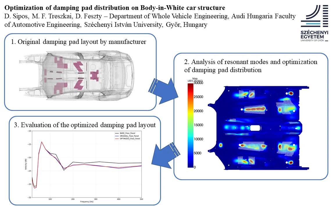
Structure-born noise is one of the most important contributors to the interior noise in a vehicle cabin. This can be effectively reduced by placing damping pads with special material properties along the chassis and on the large, radiating panels. This paper proposes a new methodology for the optimization of placing these pads as a part of a full vehicle acoustic simulation in Actran Virtual SEA. With this new strategy, it was possible to reduce the among of damping pads on a real car structure by 33 % while keeping the same acoustic performance. This was validated by investigating the mean velocity of the floor panel in two load cases and compared to the original damping pad layout to the optimized one.
Highlights
- The described method can be used to easily identify the areas where high response is expected
- With the described method, an optimization of damping pad distribution has been performed
- As a result of the optimization, similar NVH performance was achieved using 33% less weight of the damping pads
1. Introduction
The noise and vibrational comfort of passenger vehicles is one of the most important factor of customer satisfaction. Therefore, high efforts are being made by acoustical engineers to improve the NVH (Noise, Vibration and Harshness) performance of the products. In the early development phase, one can only rely on CAE (Computer Aided Engineering) methods such as FEM (Finite Element Method), SEA (Statistical Energy Analysis) etc. to assess the acoustic behavior of the current design cycle, since no prototype is available to perform measurements. These methods are well-established, and they can provide reliable results in their respective frequency domain.
The overall goal of the design process in NVH development is to reduce the noise in the passenger compartment of the vehicle. There are two main sources from which noise could originate. One is called structure-born noise. The chassis transfers the excitation from the suspension, engine, and gearbox mounts to the large panels of the vehicle which radiate noise inside the cabin. The typical frequency of structure-born noise is below 500 Hz. The other source of cabin noise is air-born, which means it is caused by the pressure fluctuations in the surrounding air of the vehicle. The noise emitted by the surface of the engine or the turbulence behind the side mirrors are typical examples of air-born noise sources. These are dominant mainly in the high-frequency range of the cabin noise.
The noise inside the passenger compartment can be reduced depending on its source and frequency range. Damping pads with high damping coefficient can be efficiently applied to reduce the vibrations of large panels of the structure by their damping and mass effect. Multilayered acoustic trim parts with porous materials act as a spring-mass system thus insulate panel vibrations from the cavity. Their mass and damping effects also contribute to the overall damping of the structure. Porous materials inside the cabin provide absorption effect too, which helps noise attenuation.
2. Literature review
Several work can be found in literature covering these topics. S. Subramanian, et. al., [1] developed a methodology to enhance the effectiveness of the damping treatments in a vehicle structure. They used modal strain energy of the bare structure panel to identify the location and the size of the damping treatments. The numerical results were compared with laser vibrometer measurements. The road noise comparison showed that 2.5 dB(A) noise reduction could be achieved in the 200-400 Hz frequency range with the optimized configuration. The main advantages of this methodology according to the authors is its simplicity, it is reasonably accurate, and the computation takes less time than the experimental approaches. In addition, it can be used in the early stage of the design.
E. Balmés, S. Germés [2] introduced a design strategy for the viscoelastic treatments placing with tools of the simulation for a full vehicle. They used the frequency weighted average strain energy for the first 50 modes to determine the place of the damping treatments. This methodology can be used to optimize large models in the early design phase.
M. Furukava, et. al. [3] compared three different passenger vehicle cases: a) Body-in-White, b) with asphalt pad and c) with liquid applied sprayable damper. They used experimental tools to determine the position of the damping materials and to reduce the application area of them. The investigated frequency range was 0-1 kHz, and they divided the vehicle components to different subsystems, and investigated the vibroacoustic behaviour in third-octave bands. They used the acceleration values to determine the position of the damping materials. As a result of their work, the application area reduced 26.3 % and the added material was 53.7 % of the original setup. The main drawback of this method is that it needs to have access to a prototype.
D. F. Comesana, J. Tatlow [4] investigated the particle velocity maps of the different car components. This way they defined the critical areas where the damping materials were applied, then the measurement was repeated, and the results were compared. Different material type, position and thicknesses were used to achieve the highest Particle Velocity Level difference in dB(A) compared to the undamped structure. The authors proposed a quick and efficient way to characterise the vibro-acoustic behaviour of the car structure, however, the main problem of this method is that the measurement process require a real car structure.
D. Hara, G. O. Özgen [5] investigated the performance of the foam cored sandwich structures instead of damping treatments on the panels of the vehicle structures e.g., on the floor, on the firewall. As the results showed the foam cored sandwich material had the same bending stiffness performance as the sheet metal panels with at least 50 % less weight. The authors recommend the sandwich structure with a viscoelastic core instead of the sheet metal with added damping treatments because it could reduce weight approximately 60-70 % keeping the same damping performance.
Guellec et at. [6] performed a complete trim package optimization for a passenger car floor panel in a two-phase design process. In the first step, they used a topology optimization algorithm to modify the beads and embossments of the panel. Then in the second stage, they optimized the bitumen and porous material properties to achieve the best possible configurations with optimal overall damping and with optimized mass. With these two configurations, they managed to achieve 2.8 dB and 2.5 dB RMS reduction of the averaged PSD pressure at the microphones in the cavity, respectively.
This paper proposes a new and user-friendly methodology to identify those areas on a vehicle structure, where the modal activity is higher, thus allowing the optimization of the damping pad placement along the structure. Its advantage is that it is not necessary to perform extra calculations, as these results can be obtained during a complete acoustic analysis. The effectiveness of this methodology is presented on a real vehicle model in Body-in-White (BIW) configuration.
3. Simulation methodology
The proposed method is based on a Virtual SEA simulation in MSC Actran. In the first step of the solution sequence of such analysis, a reduced energy model is built by assembling distribution matrices and on element patch level (set of elements), which is obtained by projecting the stiffness and mass matrices and on modal basis as [7]:
The distribution matrices can be directly used for computing energetic quantities on element patches. Then, a reduced energy model can be built and used to perform a virtual Power Injection Method (PIM) as shown in Eq. (3):
where is the matrix of injected powers. From this, the matrix of coupling and damping loss factors, can be expressed by multiplying both sides with the invert of matrix . Once this matrix is available, the model works as a classical SEA model that can be run with different boundary conditions at low computational cost [7].
MSC Actran is able to compute local responses during a Virtual SEA simulation by computing an auxiliary scalar output field , on each subsystem during the build distribution matrices sequence. This distributes the energy of a subsystem across its nodes. This output field is proportional to the square of the resonant modes in each frequency band and is normalized, so the energy of the subsystem can be retrieved by integrating over local results of the subsystem. For any given output node , squared velocity or squared pressure results can be retrieved by scaling the subsystem energy by the evaluated at node . This is expressed in Eq. (4), where denotes the subsystem containing node :
By plotting this scalar field, the optimal positions of the damping pads can be easily determined, because it shows exactly where to expect high local responses. No extra calculations are necessary, since the computation sequence is part of the Virtual SEA simulation which requires the calculation of the modes, mass, and stiffness matrices [7].
4. Simulation model setup
In this paper, a full vehicle model is presented in BIW configuration in three types of setups. The finite element model of the vehicle structure shown by Fig. 1 consists about 560k linear elements and 550k nodes. The first setup is a bare model without damping pads to identify those areas on the floor panel on which applying damping pads would be effective. The second setup uses the original damping pad layout by the manufacturer and the third one is a weight-optimized model. The original layout of the damping pads is shown by Fig. 2. The damping pads are made of bitumen material, the properties of which is summarized in Table 1. The total mass of the damping layers in the original setup is 3.98 kg and the covered area is 0.78 m2.
Table 1Material properties of bitumen damping layers
Young’s modulus | 400 MPa |
Density | 1.967-2596 kg/m3 |
Poisson ratio | 0.27 |
To compare the effect of the different layouts, a full Virtual SEA simulation is performed, and the mean squared velocity of the floor panel subsystem is compared for each setup due to a unit point force excitation in two load cases.
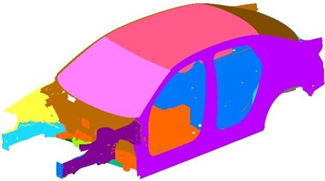
As described before, the analysis requires the modal database and the mass and stiffness matrices of the model. The normal modes of the structure were calculated to up 560 Hz and the matrices were extracted using MSC Nastran. The Virtual SEA models of each setup were built up with 1 % constant damping defined for the entire vehicle structure in each case, 36.6 % damping defined for the bitumen layers in setup number two (original model) and three (optimized model). The partitioning of the Virtual SEA model is shown by Fig. 3.
Fig. 1Finite element model of the car structure
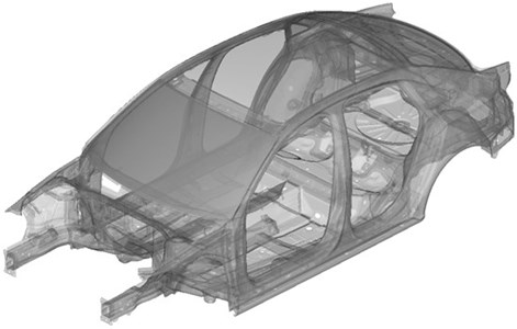
Fig. 2Original damping pad layout by manufacturer
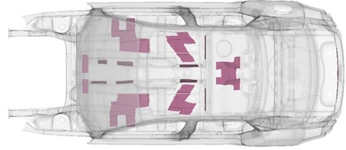
Fig. 3SEA subsystems of the vehicle
5. Simulation results
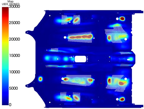
Fig. 4 shows the results of setup number one, without damping pads. The field is shown on the floor panel which is used to calculate local responses at a later stage of a Virtual SEA simulation. In the areas, where takes high values, high local responses are expected, and these are very easy to identify. It can be observed on Fig. 5, which shows the original damping pad layout and the results of the bare configuration that most of these areas are covered by bitumen layers. However, according to the results, there are also some areas were α takes low values but covered by bitumen layers which seems to be unnecessary and could be removed. Fig. 6 shows the new weight-optimized layout where the damping pads were removed from these areas. Compared to the original setup where the total mass of the damping pads was 3.98 kg, the new setup weights only 2.68 kg which is about 33 % reduction. In term of coverage, the total surface covered by the damping pads in the optimized layout has dropped from 0.78 m2 to 0.548 m2 which is about 30 % decrease.
Fig. 4Field alpha of the bare floor model
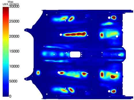
Fig. 5Original damping pad layout on the bare model results
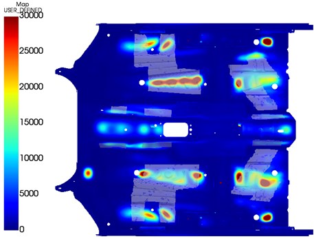
Fig. 6Optimized damping pad layout on the bare model results
To compare the results of the original and the optimized setups, the mean velocity of the floor panel was investigated in a Virtual SEA simulation. A unit point force excitation was applied in two load cases. The locations of the excitations are shown by Fig. 7.
Fig. 7Excitation load cases
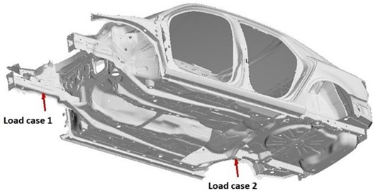
Fig. 8Mean velocity of the floor panel in three setups in load case 1
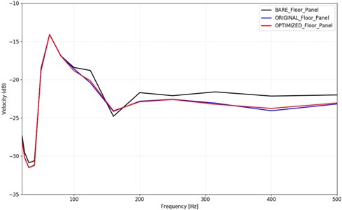
Fig. 9Mean velocity of the floor panel in three setups in load case 2
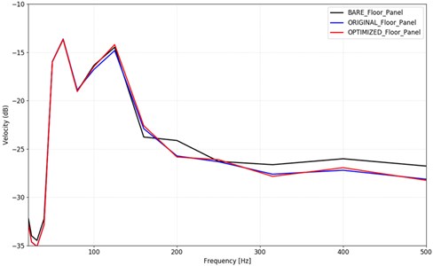
Fig. 8 shows the mean velocity of the floor panel of the three setups in load case one, where the excitation was applied on the front right frame rail, and Fig. 9 shows the same results for excitation on the rear right suspension mount. It can be observed, that starting from 100 Hz, the effect of the damping pads becomes significant. The mean velocity of the floor panel is about 1-1.5 dB lower in the two setups, where damping pads were used compared to the bare model. The difference between the original and the optimized setup is negligible. These curves suggest that similar performance as the original setup can be achieved with the optimized model, with 33 % less weight of the damping pads.
6. Conclusions
There are several methods to find the optimal location of damping pads on any given structure, where usually the modal activity is the highest. This paper presents a novel method, based on the scaling factor of subsystem energy levels, to find these critical areas effectively as part of a complete Virtual SEA simulation. This allows acoustics developers to determine the most optimal damping pad distribution on a structure with minimal effort and computational cost. The effectiveness of the method was presented by comparing the original and an optimized damping pad layout on a Body-in-White car structure. It was shown that with the optimized layout, similar NVH performance can be achieved on the floor panel of the car structure as with the original setup, but with 33 % less weight. This might aid to increase the efficiency of high-volume production of vehicles, as well as to optimize the damping layer mass for higher category models.
References
-
S. Subramanian, R. Surampudi, K. R. Thomson, and S. Vallurupalli, “Optimization of damping treatment for structure borne noise reduction,” SAE 2003 Noise and Vibration Conference and Exhibition, pp. 14–17, May 2003, https://doi.org/10.4271/2003-01-1592
-
Etienne Balmes and Sylvain Germes, “Design strategies for viscoelastic damping treatment applied to automotive components,” in Proceedings of the International Modal Analysis Conference, Feb. 2004.
-
M. Furukava, S. Gerges, M. M. Neves, and B. J. L. Coelho, “Analysis of structural damping performance in passenger vehicles chasis,” The Journal of the Acoustical Society of America, Vol. 126, No. 4, p. 2280, 2009, https://doi.org/10.1121/1.3249345
-
D. F. Comesaña and J. Tatlow, “Designing the damping treatment of a vehicle body based on scanning particle velocity measurements,” in American Control Conference, 2018.
-
D. Hara and G. O. Özgen, “Investigation of weight reduction of automotive body structures with the use of sandwich materials,” Transportation Research Procedia, Vol. 14, pp. 1013–1020, 2016, https://doi.org/10.1016/j.trpro.2016.05.081
-
A. Guellec, M. Cabrol, J. Jacqmot, and B. van den Nieuwenhof, “Optimization of trim component and reduction of the road noise transmission based on finite element methods,” in 10th International Styrian Noise, Vibration and Harshness Congress: The European Automotive Noise Conference, Jun. 2018, https://doi.org/10.4271/2018-01-1547
-
Free Field Technologies: Actran 2020 User’s guide Vol. 1: Installation, Operations, Theory and Utilities, 2020.
About this article

The research project described in this paper was supported through the funding from the Lendület Program of the Hungarian Academy of Sciences sponsoring the MTA-SZE Lendület Vehicle Acoustics Research Group.
