Abstract
In this paper, we investigate the performance of a new lead rubber damper (LRD) and its applicability to a full-scale structure. This device is more advanced than existing lead-rubber based isolation devices. In contrast to the existing devices, multiple lead cores are installed in the LRD in order to enhance the performance of the laminated rubber and lead. It is able to perform effectively under the application of shear force. An experiment was performed to investigate its dependency on the level of shear strain and frequency. The applicability of this new device to a full-scale structure is also examined by performing a vibration test on a five floor modal-test tower.
1. Introduction
In recent years, a demand on the earthquake resistant and isolation technologies has been consistently increasing due to the occurrence of huge earthquakes that resulted in massive damage and devastation such as 2010 Haiti earthquake and 2011 Tohoku earthquake in Japan. In order to mitigate the seismic damage, many different types of dampers have been developed such as magneto-rheological fluid (MRF) dampers [1-4], liquid dampers [5, 6] and lead rubber type dampers [7, 8]. In addition, various theoretical models [9-12] also have been proposed to evaluate the performance of these dampers.
The lead rubber bearing (LRB) is a representative lead rubber type damper and one of the most commonly used earthquake isolation devices. Its typical shape and hysteresis curve are illustrated in Fig. 1. It has a simple structure where a lead core is installed at the center of laminated rubber. It retains high restoration and damping force, and the natural period of structures can be increased by using it.
This study investigates the performance of a new lead rubber damper (LRD) shown in Fig. 2, which is more advanced than the existing LRB. In contrast to the LRB, multiple lead cores are installed in the LRD in order to enhance the performance of the laminated rubber and lead. The lead rubber damping device is reusable even after experiencing an event of earthquakes since both of rubber and lead have an ability to restore its original shape once shear deformation has taken place. However, if the size of a lead core is large, it diminishes the restoration force of the material. Therefore, multiple lead cores are included in the new damper, instead of using a single large core. The new LRD can show an excellent performance when subjected to seismic shear force.
Two important variables in utilizing a damper to effectively resist predetermined seismic loads are its effective stiffness and equivalent damping ratio. There are many characteristics that can affect these two variables such as the dependency on displacements, frequencies, vertical pressures, temperature and the level of shear strain. Among these, the dependency on the level of shear strain and frequency of the new damper is investigated by performing an experiment. In addition, the applicability of this new device to a full-scale structure is also examined by performing a vibration test on a five floor modal-test tower.
Fig. 1Shape of lead rubber damper (LRB) and hysteresis curve
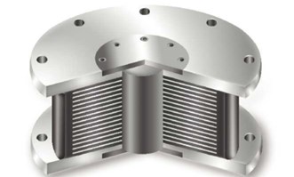
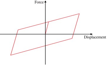
Fig. 2Lead rubber damper (LRD) and cross sectional shape
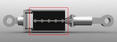
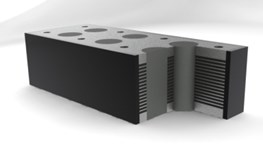
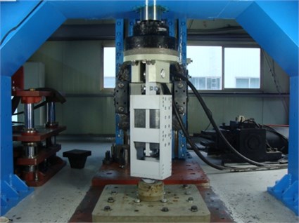
Fig. 3Test setup
2. Experimental program
The proposed LRD was designed by considering several factors such as its shape factor, stiffness and equivalent damping ratio. It size is 500 mm×300 mm×100 mm. The total thickness of the laminated rubber excluding the insert plate is 32 mm. 15 lead cores, of which size are D30 mm×100 mm, are inserted into the device. An experiment was performed using a fatigue testing machine to investigate the characteristics of the LRD. The test setup is illustrated in Fig. 3. Two LRD pads were used as a single specimen, and lateral force was applied to the specimen by the actuator with maximum capacity of 500 kN while vertical force by the actuator with maximum capacity of 2,000 kN. The details of the fatigue testing machine are given in Table 1.
Table 1Maximum capacity of the fatigue testing machine
Vertical direction | Horizontal direction | |
Load (kN) | 2 | 500 |
Displacement (mm) | ±100 | ±200 |
Velocity (mm/sec) | 100 | 200 |
3. Dependency on different level of shear strain
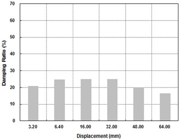
In order to investigate the dependency of the device on the level of shear strain, a cyclic lateral loading was applied to the specimen for five different levels of shear strain such as ±20 %, ±50 %, ±100 %, ±150 % and ±200 % by following the guidelines in [13]. The total number of cycles of the applied lateral load is 12, and its frequency is 0.1 Hz for all cases. The level of shear strain is determined by the lateral displacement imposed by the actuator. For instance, since the height of the laminated rubber is 32 mm, the lateral displacement for the shear strain of ±100 % is ±32 mm. The temperature of the room where the test was performed was 23 °C. The results of the test are presented in Table 2 and the hysteresis curves are given in Fig. 4. The effective stiffness and energy dissipated per cycle for different level of shear strain are plotted Fig. 5. It indicates that the effectiveness stiffness of the device decreases as the level of shear strain increases while the energy dissipated per cycle (EDC) increases with increasing level of shear strain. In contrast, as shown in Fig. 6, its equivalent damping ratio did not show any trend, and its average is approximately 22 %.
Table 2Results of the shear strain dependency test
Shear strain (%) (displacement (mm)) | 10 (3.2) | 20 (6.4) | 50 (16) | 100 (32) | 150 (48) | 200 (64) |
Effective stiffness (kn/mm) | 50.59 | 39.27 | 25.13 | 17.00 | 13.18 | 11.95 |
Energy dissipated per cycle (kn·m) | 0.56 | 2.21 | 9.33 | 24.59 | 36.40 | 47.27 |
Equivalent damping ratio (%) | 20.80 | 24.70 | 25.00 | 24.90 | 20.10 | 16.60 |
Fig. 4Hysteresis curves of the shear strain dependency test
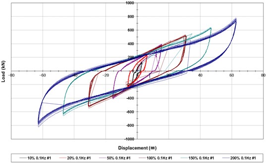
Fig. 5Effective stiffness and energy dissipated per cycle for different level of shear strain
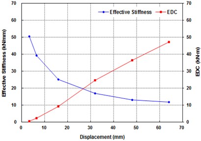
Fig. 6Equivalent damping ratio for different level of shear strain
4. Dependency on different level of frequency
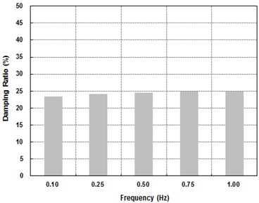
Similarly to the shear strain dependency test, the frequency dependency of the device was investigated by applying the lateral displacement corresponding to the shear strain of 50 % for five different levels of frequency such as 0.1 Hz, 0.25 Hz, 0.5 Hz, 0.75 Hz and 1.0 Hz. The total number of cycles of the applied lateral load is 12 for all cases. The results of the test are presented in Table 3 and the hysteresis curves are given in Fig. 7. The effective stiffness and EDC for different level of shear strain are plotted Fig. 8. The equivalent damping ratio for different level of shear strain is presented Fig. 9. All of these results indicate that the effective stiffness, EDC and equivalent damping ratio are not affected by the level of frequency. This seems to happen because the equivalent damping ratio of rubber is significantly lower than that of lead and the recrystallization of lead does not depend on the frequency of loading. Consequently, the dependency of the laminate rubber on frequency determines the overall dependency of the device, leading to the insensitiveness of the device to the level of frequency.
Table 3Results of the frequency dependency test
Frequency (Hz) | 0.10 | 0.25 | 0.50 | 0.75 | 1.00 |
Effective stiffness (kN/mm) | 25.31 | 26.54 | 27.18 | 27.85 | 27.38 |
Energy dissipated per cycle (kN·m) | 23.40 | 24.20 | 24.50 | 24.80 | 24.90 |
Equivalent damping ratio (%) | 8.85 | 9.11 | 9.13 | 8.83 | 8.86 |
Fig. 7Hysteresis curves of the frequency dependency test
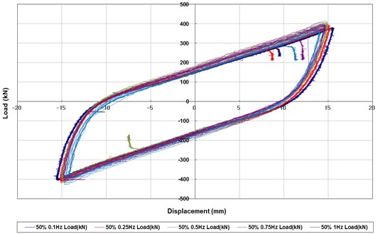
Fig. 8Effective stiffness and energy dissipated per cycle for different level of frequency
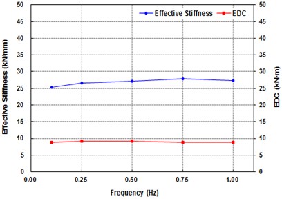
Fig. 9Equivalent damping ratio for different level of frequency
5. Application of the proposed lead rubber damper to full-scale structures
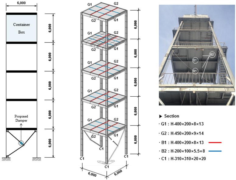
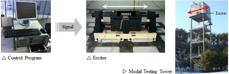
This section experimentally investigates the applicability of the proposed LRD to a full-scale structure. The full-scale test model is the modal test tower with five floors, which is shown in Fig. 10. The dimension of each floor is 6 m×6 m×6 m, and four H-shape steel columns exist at the corners of each floor. A vibration exciter was located at the top floor, and the LRD was installed at the base floor in the form of the toggle bracing system as shown in the figure. This is similar to the toggle-brace-damper system discussed in [14], and a small LRD with a single core was used in the toggle bracing system, instead of the normal size LRD illustrated in Fig. 2. Two cases with and without this bracing system were considered to investigate the effectiveness of the proposed LRD. As illustrated in Fig. 11, the vibration at each floor was measured using six accelerometers, and the measured data with/without the bracing system were stored on a desktop computer through a signal conditioner and A/D board. The excitation details are also provided in the figure.
Fig. 10Modal test tower and toggle bracing system with the proposed LRD (unit: mm)
A harmonic excitation signal provided by the vibration exciter is presented in Fig. 12. The excitation was continued during 60 seconds, and the vibration of the structure was measured at each floor until it became negligible. The vibration signal was 2 V. The vibration frequency of the exciter was increased from 0.49 Hz to 0.63 Hz with an increment rate of 0.01 Hz. This is because the natural frequencies with and without the toggle bracing system were expected to be 0.55 Hz and 0.60 Hz, respectively, from the result of a simple modal analysis of the test structure, which was obtained using the commercial software ANSYS [15]. Then the frequency that produces the maximum displacement was found from the measured data at each floor.
Fig. 13 presents the maximum displacement measured at each floor for the cases with and without the toggle bracing. As expected, the maximum displacement is generally proportional to the height of the floor, thus the peak value of the maximum displacement always exists at the fifth floor in the entire range of excitation frequencies. The peak value of the maximum displacement is 84 mm at 0.55 Hz in the case without the bracing. After installation of the bracing, it is 82 mm at 0.62 Hz. This indicates that the natural frequency of the test structure changed from 0.55 Hz to 0.62 Hz by installing the toggle bracing in the structure and the peak value of the maximum displacement has been reduced by approximately 3 %.
Fig. 11Test setup illustration
a) Excitation details
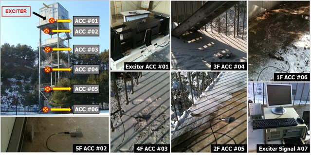
b) Locations of installed accelerometers in the modal test tower
Fig. 14 shows the maximum displacement plots of the second and fifth floors before and after installation of the bracing. At the second floor, the maximum displacement is decreased after bracing installation in the entire range of vibration frequencies. However, the maximum displacement value does not change significantly at the fifth floor. This shows that the reduction of the maximum displacement due to the installation of the toggle bracing with the proposed LRD is more significant at relatively low floors.
Fig. 12Excitation signal
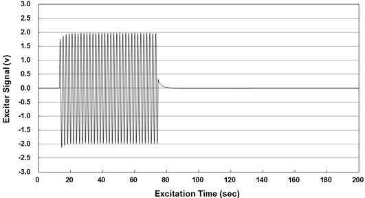
Fig. 13Maximum displacement measured at each floor for the system with and without the bracing
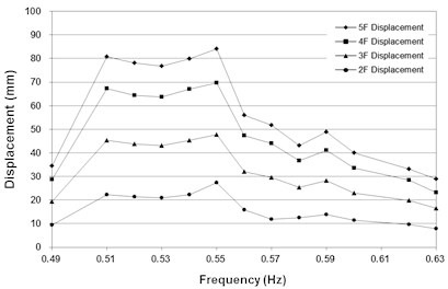
a) Case without the bracing
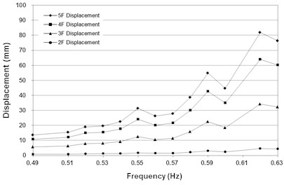
b) Case with the bracing
Fig. 14Maximum displacement measured at the second and fifth floor of the test structure
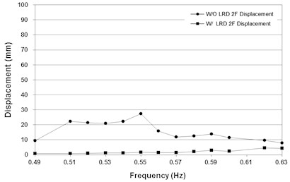
a) Second floor
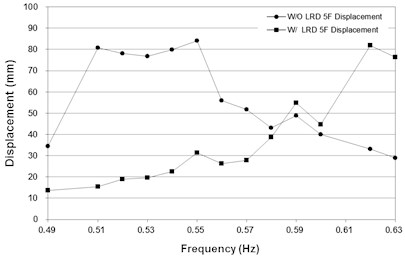
b) Fifth floor
6. Conclusions
In this study, an experiment was performed to investigate the dependency on the level of shear strain and frequency of the newly proposed LRD, and its equivalent damping ratio, energy dissipation capacity and effective stiffness were evaluated. The applicability of this new device to a full-scale structure is also examined by performing a vibration test on a five floor modal-test tower. The following conclusions can be drawn from the test results:
1) The results of the shear strain dependency test show that the effectiveness stiffness of the device decreased as the level of shear strain increased while the energy dissipated per cycle (EDC) increased with increasing level of shear strain. In contrast, its equivalent damping ratio did not show any trend, and its average is approximately 22 %.
2) The results of the frequency dependency test indicate the effective stiffness, EDC and equivalent damping ratio of the device are not affected by the level of frequency. This seems to happen because the equivalent damping ratio of rubber is significantly lower than that of lead and the recrystallization of lead does not depend on the frequency of loading. Consequently, the dependency of the laminate rubber on frequency determines the overall dependency of the device, leading to the insensitiveness of the device to the level of frequency.
3) In the results of the full-scale model test to investigate the effectiveness of the proposed LRD, the maximum displacement is generally proportional to the height of the floor, thus the peak value of the maximum displacement always exists at the fifth floor in the entire range of excitation frequencies
4) The full-scale model test results show that the natural frequency of the test structure changed from 0.55 Hz to 0.62 Hz by installing the toggle bracing with the proposed LRD in the structure, but the peak value of the maximum displacement has been reduced by approximately 3 %. In addition, the reduction of the maximum displacement is more significant at relatively low floors rather than at high floors.
References
-
Dragasius E., Grigas V., Mazeika D., Sulginas A. Evaluation of the resistance force of magnetorheological fluid damper. Journal of Vibroengineering, Vol. 14, 2012, p. 1-6.
-
Milecki A. Investigation and control of magneto-rheological fluid dampers. International Journal of Machine Tools and Manufacture, Vol. 41, 2001, p. 379-391.
-
Wang X., Gordaninejad F. Lyapunov-based control of a bridge using magneto-rheological fluid dampers. Journal of Intelligent Material Systems and Structures, Vol. 13, 2002, p. 415-419.
-
Kim J., Lee S., Min K.-W. Design of MR dampers to prevent progressive collapse of moment frames. Structural Engineering and Mechanics, Vol. 52, 2014, p. 291-306.
-
Lee S.-K., Park E. C., Min K.-W., Lee S.-H., Chung L., Park J.-H. Real-time hybrid shaking table testing method for the performance evaluation of a tuned liquid damper controlling seismic response of building structures. Journal of Sound and Vibration, Vol. 302, 2007, p. 596-612.
-
Min K.-W., Kim J., Lee H.-R. A design procedure of two-way liquid dampers for attenuation of wind-induced responses of tall buildings. Journal of Wind Engineering and Industrial Aerodynamics, Vol. 129, 2014, p. 22-30.
-
Chung G. Y., Ha D. H., Park K. N., Kim D. H. Experimental study on characteristics of LRB with low hardness rubber. Journal of the Korean Society of Civil Engineers, Vol. 22, Issue 6A, 2002, p. 1295-1307, (in Korean).
-
Robinson W. H. Lead-rubber hysteretic bearings suitable for protecting structures during earth-quakes. Earthquake Engineering and Structural Dynamics, Vol. 10, 1982, p. 593-604.
-
Truhar N. An efficient algorithm for damper optimization for linear vibrating systems using Lyapunov equation. Journal of Computational and Applied Mathematics, Vol. 172, 2004, p. 169-182.
-
Wongprasert N., Symans M. Application of a genetic algorithm for optimal damper distribution within the nonlinear seismic benchmark building. Journal of Dynamic Systems, Measurement, and Control, ASME, Vol. 130, 2004, p. 401-406.
-
Savaresi S. M., Silani E., Bittanti S. Acceleration-driven-damper (ADD): an optimal control algorithm for comfort-oriented semiactive suspensions. Journal of Engineering Mechanics, ASCE, Vol. 127, 2004, p. 218-229.
-
Lee H.-J., Jung H.-J., Moon S.-J., Lee S.-K., Park E.-C., Min K.-W. Experimental investigation of MR damper-based semiactive control algorithms for full-scale five-story steel frame building. Journal of Intelligent Material Systems and Structures, Vol. 21, 2010, p. 1025-1037.
-
Elastomeric Seismic-protection Isolators Part 1: Test methods. International Standard, ISO 22762-1, 2005.
-
Hwang J. S., Huang Y. N., Hung Y. H. Analytical and experimental study of toggle-brace-damper systems. Journal of Structural Engineering, ASCE, Vol. 131, 2005, p. 1035-1043.
-
ANSYS Mechanical Theory Manual. 2010.
About this article

This work was supported by the National Research Foundation of Korea (NRF) Grant funded by the Korea Government (MSIP) (NRF-2011-0016332).
