Abstract
This study proposes a novel and efficient approach for locating the floors of a building whose stiffnesses change after being subject to a strong earthquake. The floors that may be damaged are determined by comparing the unitary stiffness matrix in different stages in the life cycle of a building. To evaluate the coefficient matrices of a state-space model, the proposed procedure applies a subspace approach in conjunction with the short time Fourier analysis. The dynamic characteristics of a structure are determined from the coefficient matrices. Next, the unitary stiffness matrix is constructed by identifying natural frequencies and mode shapes. The effectiveness of the proposed procedure is verified using the measured earthquake acceleration responses of a three-storey structure that sustains damage on one or two floors and an eight-storey steel frame under a 200 Gal and a 1200 Gal earthquake, such as the Chi-chi earthquake that shook Taiwan on September 1999. The proposed scheme is compared to mode shape based approaches in identifying damaged floors, and is demonstrated to be superior to both MAC (Modal Assurance Criterion) and COMAC (Coordinate Modal Assurance Criterion).
1. Introduction
Using the identified modal parameters of an existing structure or bridge from measured responses to locate damaged locations is essential in the field of structural health monitoring. In literature, there are vast algorithms for identifying modal parameters of a structure from its dynamic responses. The approaches of system identification are divided into broad categories, parametric and nonparametric identification approaches.
– The parametric approach methods uses a chosen time series model and estimates the model parameters from a regression process of the measured data. Auto-regressive (AR), auto-regressive exogenous (ARX), auto-regressive moving average (ARMA), auto-regressive moving average exogenous (ARMAX) methods [1-4], stochastic subspace approaches [5, 6] and Ibrahim time domain schemes [7] have been frequently used to identify modal parameters of civil structures.
– The nonparametric approach is performed by estimating the dynamic characteristics of a structure without necessarily using a given parameterized model. Correlation and spectral analyses are often used to estimate impulse response function and frequency response functions, respectively, in the nonparametric approach [8]. However, they do not work well for structural systems with heavy damping and strong modal interference.
The method of damage identification based on examining change in measured vibration responses is the vibration-based damage detection method. Most vibration-based damage detection methods can be classified by identifying their dynamic properties [9, 10]:
– Natural frequency based methods: applying identified natural frquency from measured structural responses for detcting structural damage locations [11-13].
– Mode shape based methods: developing a damage index from identified modal shapes to locate floors with structural damage [14-16].
– Stiffness matrix based methods: comparing the difference of the identified stiffness matrix between the damaged and undamaged structure to assess structural damage [17-19].
– Flexibility matrix based methods: using identified modal parameters and given mass properties to construct a flexibility matix to identify damaged locations [20, 21].
– Frequency response function based methods: frequency response function is a transfer function in the frequency domain, with dissimilarities between frequency responses functions for damaged and undamaged states used to identiy the damage [22, 23].
This work presents a simple and efficient stiffness-based approach to determine which floors of a structure exhibit a change in stiffness. First, the state-space model of structure is established and a subspace approach is used to estimate modal parameters. The measured responses are in terms of acceleration or velocity, and the acceleration responses are used in this approach. Next, the unitary stiffness matrix can be constructed via the identified modal parameters. The unitary stiffness matrix in the reference stage (without damage) are then compared with those in the current state (possibly damaged) and, by using the singular value decomposition (SVD), the location of any damaged floors can be easily determined. The state-space models are developed via the short time Fourier transform.
The proposed procedure is validated using the measured earthquake acceleration responses of a three-storey steel frame and an eight-storey steel frame. A series of cases, involving single-site and dual-site damage, is examined for the three-storey frame. In another, the eight-storey frame was subjected to 200 Gal and 1200 Gal earthquake forces. For comparison, the MAC and COMAC is also adopted for damage detection.
2. Methodology
2.1. Subspace approach in time-frequency domain
The dynamic responses of a linear structure satisfy the equation of motion:
where , and are mass, damping and stiffness matrices, respectively; , and are the acceleration, velocity, and displacement responses vectors of the system, and is the input force vectors. Usually, not all degrees of freedoms of system are measured in a field experiment, for reasons of economy. Only some parts of or are measured. Consequently, the measured response vector , which can be velocity or acceleration responses, can be described by the state-space model. Generally, the state-space model considered in the following will be presented as [5]:
where , , and are system matrices that relate to , and ; is state-variable .
From Eq. (2), one can construct:
In the frequency domain, one can arbitrarily remove uninteresting frequency-bands to reduce the effects of noise in accurately estimating the modal parameters of a linear time invariant system. Consequently, Fourier transform is further introduced into Eq. (3). Treating the columns of , and as vector functions and applying the Fourier transform to Eq. (3) yields:
Via Eq. (4), one can further construct:
where:
where the two sets and are the short-time Fourier transform coefficients of and , respectively. From Eq. (5), the following relation can be established:
where:
For further details of subspace system identification approaches, see Huang and Lin [5], and the references therein. As a brief summary, the subspace approach procedure is as follows:
1) Define an orthogonal projection matrix , onto the null-space of .
2) Introduce instrumental variables .
3) Calculate weighting matrices and .
4) Define a matrix .
5) Apply singular value decomposition on .
6) One has , where ; .
7) Rewrite Eq. (5) as , where .
8) can be established by .
9) Define:
10) Calculate by solving linear equation .
2.2. Determination of modal parameters
When the equation of motion is expressed in terms of the space-state variable, it is well known that the dynamic characteristics of the structural system are determined by the eigenvalues and eigenvectors of in Eq. (2a). However, cannot be determined from the preceding derivation. Thus, to find the modal parameters, is employed:
where and are the th eigenvalue of and , respectively, while and are the corresponding eigenvectors. Since remains unknown, the eigenvectors of from Eq. (9) cannot be evaluated. Nevertheless, usually, one only needs to determine the modal shape corresponding to the observed degrees of freedom, . From the procedure in Section 2.1, the following relationship can be determined:
The eigenvalues are complex numbers. Let:
From Eq. (9), one has:
Then, the pseudo-undamped circular natural frequency and the modal damping ratio for the system are:
In a proportionally damped system, this is equivalent to its undamped circular natural frequency.
2.3. Damage assessment
Consider the response of a structure described by equation of motions such as Eq. (1). Assuming proportional damping, the orthogonality property of the mode shapes with respect to the mass and stiffness matrix leads to [24]:
in which and are the diagonal modal mass matrix and diagonal modal stiffness matrix, respectively. The equation used to express the square of modal frequencies as a matrix is:
Here, the unitary stiffness matrix were defined as:
The unitary stiffness matrix at the sensor locations constructed from measured data before and after damage are denoted as and , respectively. Applying singular value decomposition (SVD) to yields:
The singular values are the difference in potential energy between and under each state and . The location of maximum relative displacement in each and that lead to the difference of potential energy implies the maximum difference between the damaged and undamaged systems. Therefore, the possible damaged floors can be identified by nonzero singular values and corresponding states and . The damage index can be obtained from the following steps:
1) Find the location () with maximum relative displacement in or .
2) Define damage index ():
3. Applications
To demonstrate the feasibility of the proposed procedure in processing data in real applications, the procedures were applied to identify the modal parameters of structures from their measured response data obtained from shaking table tests.
3.1. Three-storey steel frame
Shaking table tests are often employed in a laboratory to investigate the behaviors of structures under earthquake conditions. To generate a set of earthquake response data for a benchmark model of a 1/8-scaled three-storey steel structure, CV-NCTU (Department of Civil Engineering, National Chiao Tung University) performed a series of shaking table tests on three frames (Fig. 1). One steel frame was represented as “std”, where each floor weighed about 3.8 kg and each column had a cross-sectional area of 80 mm2 and was 440 mm in height. The second frame and third frame, which were structurally irregular with respect to stiffness and denoted “R_k1”, were identical to “std” except that a stiffening central column was removed from the first story. The third frame, denoted as “R_k12”, was identical to “R_k1” except that the stiffening central column was removed from the second story. These frames were subjected to base excitations specified by records of real earthquakes such as the 1995 Kobe earthquake. The responses were sampled at 100 Hz. Fig. 1 depicts the acceleration responses of each floors in the weak axis direction for frame “std”, subject to 20 % of the strength of the Kobe earthquake.
Fig. 1A photo of frame “std” on shaking table and its responses
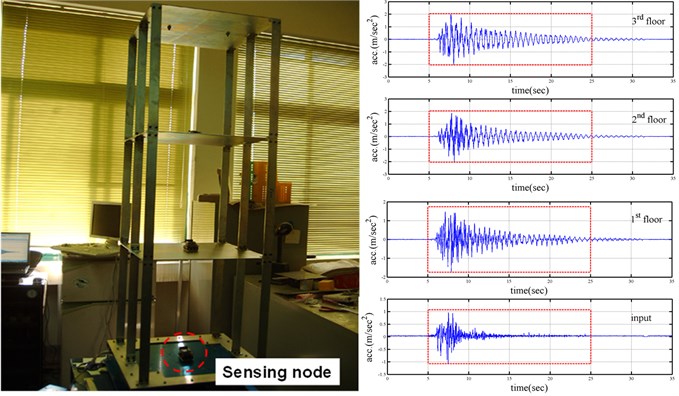
Table 1Comparison of identified modal parameters for different frames
Frame | Mode | (Hz) | (%) | Mode shapes | ||
std | 1 | 1.65 | 1.81 | 1.000 | 0.803 | 0.454 |
2 | 4.83 | 1.12 | –0.890 | 0.395 | 1.000 | |
3 | 7.22 | 0.94 | –0.513 | 1.000 | –0.789 | |
R_k1 | 1 | 1.44 | 1.16 | 1.000 | 0.843 | 0.563 |
2 | 4.53 | 0.84 | –0.912 | 0.264 | 1.000 | |
3 | 7.16 | 0.57 | –0.525 | 1.000 | –0.721 | |
R_k12 | 1 | 1.36 | 0.83 | 1.000 | 0.865 | 0.484 |
2 | 4.38 | 0.60 | –0.654 | 0.115 | 1.000 | |
3 | 6.62 | 0.91 | –0.704 | 1.000 | –0.530 | |
Table 1 summarizes the identified dynamic characteristics of the three frames obtained using the acceleration responses of all floors and the input excitation in the weak axis direction. The results were obtained from the responses of all floors at 5-25 seconds. The natural frequencies of “R_k1” and “R_k12” differ significantly from those of “std”. As expected, frame “R_k1” has lower natural frequencies than frame “std”, whereas frame “R_k12” has the lowest natural frequencies in all frames. To evaluate the correlation of mode shapes obtained from different methods and frames, the index of modal assurance criterion (MAC) [15] and coordinate modal assurance criterion (COMAC) [16] was computed to indicate the correlation between any two mode shapes of interest, and which are defined as:
To compare the identified mode shapes of undamaged frames in “std” with damaged frames in “R_k1” and “R_k12”, and respesent the deformation of the th degree of freedom in the identified mode shapes, respectively.
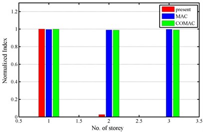
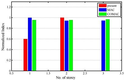
Fig. 2 compares the results obtained using the various methods. The frame “std” is treated as a reference structure. Since the MAC and COMAC values are always between zero and unity, the maximum values of the results from proposed approach were normalized to unity for comparison. The results denoted by “present” in Fig. 2 normalize the difference of potential energy between damaged and undamaged systems. Fig. 2 clearly demonstrates that the proposed approach is superior to MAC and COMAC in identifying the floor of the structure whose properties differ from those of the corresponding floor in the reference structure.
Fig. 2Normalized index
a) R_k1
b) R_k12
3.2. Eight-storey steel frame
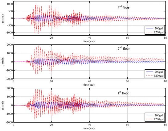
To generate a set of earthquake response data for a benchmark model of an eight-storey steel frame, the National Center for Research on Earthquake Engineering (NCREE) in Taiwan performed a series of shaking table tests on this model (Fig. 3). The eight-storey steel frame analyzed in this test was 1.8 m long, 1.2 m wide and 8.5 m high. Lead plates were piled on each floor such that the total mass of the steel frame was approximately 4.519 tons. In the shaking table tests, two accelerometers and two linear displacement transducers were installed in the long-span direction on the two edges of each floor to measure acceleration and displacement responses of the floor, respectively. The frame was subjected to base excitations equivalent to the Chi-chi earthquake at different reduced levels, including 200 Gal and 1200 Gal of base excitation levels. Data were recorded at a sampling rate of 200 Hz. The acceleration responses of the base and all floors at 5-35 seconds were used in calculating modal parameters of the frame. Fig. 4 shows the base excitations and the responses of all floors in the long-span direction of the frame, subjected to 1200 Gal, equivalent to the Chi-hi earthquake. The strain records shown in Fig. 5 for different levels of earthquake input confirm that the columns of the first to third floors yielded when the frame was subjected to 1200 Gal base excitation.
Fig. 3A photo of frame on shaking table
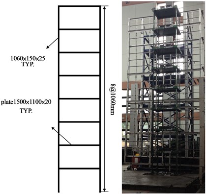
Fig. 6 shows the results of the identified modal parameters of eight modes for the steel frame under 200 Gal and 1200 Gal of the Chi-chi earthquake force. Since the frame is symmetric with eight storeys, it is expected to have eight modes in the long-span direction of the frame. Damage that is caused by a strong earthquake will change the natural frequencies of the structure.
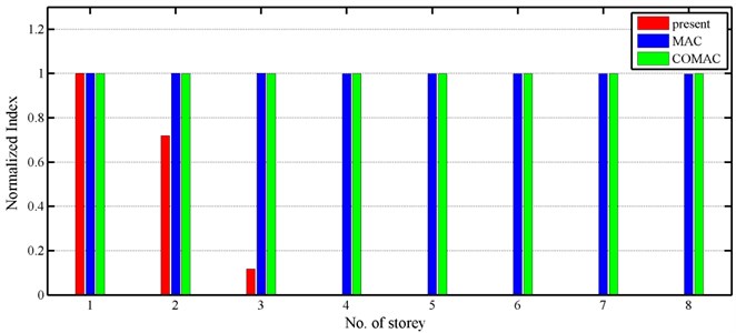
Fig. 7 compares the results obtained using the various methods. When the frame was subjected to 200 Gal of the Chi-chi earthquake, no nonlinear behaviors were observed, and it was treated as a reference structure. Again, the maximum values of the results from proposed approach were normalized to unity for comparison. The results denoted by “present” in Fig. 7 normalize the difference of potential energy between damaged and undamaged systems. Fig. 7 clearly indicates that the stiffness of the first to third floors significantly changed when the frame was under 1200 Gal of the Chi-chi earthquake, and these floors were somewhat damaged. Notably, Fig. 5 shows the measurements obtained by strain gauges installed on the columns of the first to third stories, which also indicated that the columns yielded during such base excitation. The success of the proposed procedure, as revealed in capturing the differences in properties of experimental frames, demonstrates the practical applicability of this procedure on an actual building with symmetry.
Fig. 4Responses of frame under 1,200 Gal of the Chi-chi earthquake
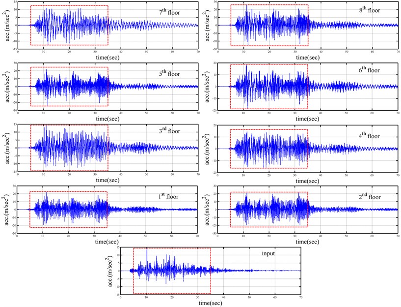
Fig. 5Strain responses at first, second and third floor columns
4. Conclusions
The work developed a simple and efficient approach for identifying the floors of a structure that sustain earthquake damage, based on the fact that such damage to a particular floor changes the stiffness matrix of the structure. This procedure was established through a state-space model to describe the measured responses. The coefficient matrices related to the dynamic characteristics were evaluated by a subspace method in conjunction with the concept of an instrumental variable. Next, the modal parameters were evaluated from the eigenvalues and eigenvectors of a coefficient matrix. The unitary stiffness matrix was constructed from identified modal parameters. The coefficient matrix was established from the acceleration or velocity responses of structure using the short time Fourier transform. Comparing the unitary stiffness matrix in the current state with those in the undamaged state enables damaged floors to be accurately located.
Fig. 6Identified natural frequency and model shape of eight-storey steel frame
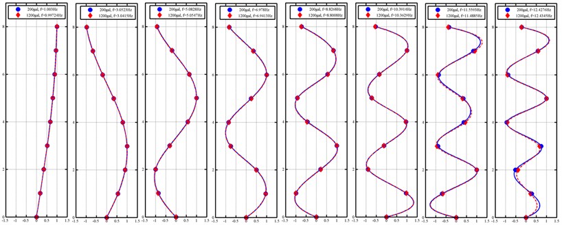
Fig. 7Normalized index
To demonstrate the feasibility of proposed approach for actual applications, this procedure was applied to process in situ earthquake response measurements of a three-storey and an eight-storey steel frame. The three-storey steel frame with single-site or dual-site damage was considered, and the eight-storey was subjected to 200 Gal and 1200 Gal earthquake forces. The proposed approach was validated by successfully identifying damaged floors through processing measured responses. Comparing the results obtained by the proposed approach with MAC and COMAC indexes revealed that the present approach is substantially superior to both in identifying damaged floors. The success of the proposed approach when applied to the experimental responses demonstrates its practical applicability to an actual symmetrical building.
References
-
Wang Z. N., Fang T. A time domain method for identifying modal parameters. Transaction of ASME, Journal of Applied Mechanics, Vol. 53, Issue 1, 1986, p. 28-32.
-
Loh C. H., Wu T. S. Identification of Fei-Tsui arch dam from both ambient and seismic response data. Soil Dynamics and Earthquake Engineering, Vol. 15, Issue 7, 1996, p. 465-483.
-
Huang C. S. Structural identification from ambient vibration measurement using the multivariate AR model. Journal of Sound and Vibration, Vol. 241, Issue 1, 2001, p. 337-359.
-
Lardies J. Modal parameter identification based on ARMAV and state-space approaches. Archive of Applied Mechanics, Vol. 80, Issue 1, 2010, p. 335-352.
-
Huang C. S., Lin H. L. Modal identification of structures from ambient vibration, free vibration, and seismic response data via a subspace approach. Earthquake Engineering and Structural Dynamics, Vol. 30, Issue 12, 2001, p. 1857-1878.
-
Ali M. R., Okabayashi T. System identification of highway bridges from ambient vibration using subspace stochastic realization theories. Earthquake and Structures, Vol. 2, Issue 2, 2011, p. 189-206.
-
Ibrahim S. R., Mikulcik E. C. The experimental determination of vibration parameters from time responses. Shock and Vibration Bulletin, Vol. 46, Issue 5, 1976, p. 187-196.
-
Bendat J. S., Piersol A. G. Engineering Applications of Correlation and Spectral Analysis, 2nd Ed. John Wiley and Sons, New York, U.S., 1993.
-
Carden E. P., Fanning P. Vibration based conditioning monitoring: a review. Structural Health Monitoring, Vol. 3, Issue 4, 2004, p. 355-377.
-
Montalvao D., Maia N., Ribeiro A. A review of vibration-based structural health monitoring with special emphasis on composite materials. Shock and Vibration Digest, Vol. 38, Issue 4, 2006, p. 295-324.
-
Adams R. D., Cawley P., Pye C. J., Stone B. J. A vibration technique for non-destructively assessing the integrity of structures. Journal of Mechanical Engineering Science, Vol. 20, Issue 2, 1978, p. 93-100.
-
Cawley P., Adams R. D. The location of defects in structures from measurements of natural frequencies. Journal of Strain Analysis, Vol. 14, Issue 2, 1979, p. 49-57.
-
Salawu O. S. Detection of structural damage through changes in frequency: a review. Engineering Structures, Vol. 19, Issue 9, 1997, p. 718-723.
-
Alampalli S., Fu G., Dillon E. W. Signal versus noise in damage detection by experimental modal analysis. Journal of Structural Engineering, Vol. 123, Issue 2, 1997, p. 237-245.
-
Allemang R. L., Brown D. L. A correlation coefficient for modal vector analysis. Proceedings of the 1st International Modal Analysis Conference, 1983, p. 110-116.
-
Lieven N. A. J., Ewins D. J. Spatial correlation of modespaces: the coordinate modal assurance criterion (COMAC). Proceedings of the 6th International Modal Analysis Conference, Kissimmee, Florida, USA, 1988, p. 1063-1070.
-
He J., Ewins D. J. Analytical stiffness matrix correction using measured vibration modes. Modal Analysis: The International Journal of Analytical and Experimental Modal Analysis, Vol. 1, Issue 1, 1986, p. 9-14.
-
Salawu O. S., Williams C. Structural damage detection using experimental modal analysis – a comparison of some methods. Proceedings of 11th International Modal Analysis Conference, 1993, p. 254-260.
-
Peterson L. D., Alvin K. F., Doebling S. W., Park K. C. Damage detection using experimentally measured mass and stiffness matrices. Proceedings of 34th AIAA/ASME/ASCE/AHS/ASC Structures, Structural Dynamics, and Materials Conference, 1993, p. 1518-1528.
-
Pandey A. K., Biswas M. Damage detection in structures using changes in flexibility. Journal Sound and Vibration, Vol. 169, Issue 1, 1994, p. 3-17.
-
Bernal D. Load vectors for damage localization. Journal of Engineering Mechanic, Vol. 128, Issue 1, 2002, p. 7-14.
-
Sampaio R. P. C., Maia N. M. M., Silva J. M. M. Damage detection using the frequency response function curvature method. Journal of Sound and Vibration, Vol. 226, Issue 5, 1999, p. 1029-1042.
-
Lee U., Shin J. A frequency response function-based structural damage identification method. Computers and Structures, Vol. 80, Issue 2, 2002, p. 117-132.
-
Tedesco J. W., McDougal W. G., Ross C. A. Structural Dynamics: Theory and Applications. Addison-Wesley, Menlo Park, Calif, 1999.
About this article
The authors would like to thank the National Science Council of the Republic of China, Taiwan, for financially supporting this research under Contract No. MOST 104-2622-M-492-001-CC2. The appreciation is also extended to the National Center for Research on Earthquake Engineering for providing shaking table test data.
