Abstract
During buffeting control of an aircraft, there consequently is a motion-induced aerodynamic force. However, it is not yet clear whether this additional force must be considered in design of control law. In this paper, to hopefully answer this interesting question, effects of the motion-induced aerodynamic force on the active buffeting control during control law design are studied. The macro fiber composite (MFC) actuator is modeled by employing the load simulation method, and the motion-induced unsteady aerodynamic forces are computed by the doublet-lattice method. Two different controllers, i.e. one with the motion-induced aerodynamic force and another without it, are simultaneously designed based on the linear quadratic Gaussian (LQG) control method. And, two corresponding models are respectively developed. Then, the control effects of the two models are compared and the physical mechanisms are discussed. From our simulation results it is found that the motion-induced aerodynamic forces do influence the buffeting responses depending on airflow velocity. The differences of the control effects of the two models are smaller at lower airflow velocity below the flutter velocity, however with the increase of the airflow velocity the control effect of the model considering the motion-induced aerodynamic force is much better. The larger the velocity is, the more significant the differences are. Finally, the energy dissipation of the motion-induced aerodynamic force is examined and found to be a main factor influencing the differences of the two models.
1. Introduction
When the modern fighter aircraft undergoes maneuvers at high angles of attack, the strong leading-edge vortices emanating from wing-fuselage interface and leading-edge extensions might break down ahead of vertical tails. As a result, the breakdown vertical flow impinges upon the vertical tails surfaces and dynamic buffet loads are generated [1, 2],which may unfortunately cause severe vibration problems of the tail structure, known as buffeting. The tail buffeting can limit the flight envelope of aircraft and shorten the fatigue life of the tail. It can also affect aircraft maneuverability, and even cause disastrous damage of the structure.
Many different approaches to tail buffeting alleviation have been studied. Essentially, they can be divided into two main categories: flow control [3-7] and structural control. However, the reduction of the buffet load by using flow control approach is limited, and this approach just supplies to certain flight conditions. Alternatively, tail rudder control [8-9] was developed as one of active structural control methods. Nevertheless, the drawback of using rudder is that it only works well at the frequency below its own driving frequency, or, it can hardly work in case of buffeting responses at high-frequency. Afterwards, piezoelectric actuator, due to its desirable electromechanical characteristics, has been popularly used to control buffeting responses. Hauch et al. [10] employed simple control techniques with piezoceramic actuators to study the feasibility of the vertical buffeting alleviation. A full-scale aircraft instrumented to alleviate the vertical fin buffeting were tested using strain actuation based on the standard time-invariant linear quadratic Gaussian (LQG) control law design [11], and very promising results were obtained. Sheta et al. [12] used a single input/single-output controller with distributed piezoelectric (PZT) actuators to present an active smart material control system. Their results showed that the buffeting responses can be effectively alleviated over a wide range of angels of attack by adopting the actively controlled PZT actuators. A simplified method of analyzing and designing a vertical tail buffeting alleviation system was developed [13] by Zhao. Wang et al. [14] performed a piezoelectric active control experiment of the tail buffeting in a wind tunnel using arching PZT actuator (APA) and principal modal control (PMC) method, and their test results indicated the validity and feasibility of the APA and PMC method for tail buffeting alleviation. The experimental evaluation of an advanced hybrid buffet suppression system on full-scale F/A-18 vertical tail structure was presented in Ref. [15] where a hydraulic rudder actuator and distributed MFC piezoelectric actuators were used. Gao et al. [16] developed an active vibration control system of the vertical fin with surface-bonded MFC actuators to reduce the dynamic vibration of vertical fin. And, the open-loop test for the system was implemented and the results validated the effectiveness of the MFC in alleviating structural vibration.
For case of buffeting control, the aerodynamic forces acting on the vertical tail surface generally include two parts [17]: one part is buffet excitation loads owing to flow separation, and the other part is the motion-induced aerodynamic forces. The motion-induced aerodynamic forces are unsteady aerodynamic forces and can be simulated by the linear model, such as doublet-lattice method (DLM). In previous studies of buffeting control, probably for simplicity and representative, the motion-induced aerodynamic forces were mostly not considered during control law design. In fact, it is still unclear whether it is necessary to consider the motion-induced aerodynamic force during buffeting control law design. And few relevant research literatures have been seen. The presented study is aimed to examine the impact of motion-induced aerodynamic forces on buffet alleviation at different airflow velocities (all below flutter velocity), so as to give an answer to whether the motion-induced aerodynamic force should be considered in buffeting control law design.
Two different controllers, i.e. one controller with the consideration of the motion-induced aerodynamic force, and another controller without the consideration, are designed by employing the LQG control method and the MFC actuator. And, two corresponding models are respectively developed. Afterwards, the control effects of the two controllers, in terms of mainly the dynamic displacement and buffet loads comparison between the open-loop and closed-loop systems are analyzed. Further discussions on energy dissipation are presented so as to explain the physical mechanisms of the impacts of motion-induced force and its differences.
2. Aeroelastic buffeting modeling
2.1. Structural and electromechanically coupled modeling
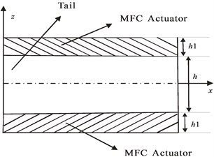
Fig. 1 shows a schematic diagram of a vertical tail with MFC actuators. The linear constitutive equation of the MFC can be written as follows:
where represents the strain vector, represents the stress vector, represents the electric displacement vector, represents the electric filed vector, is the compliance matrix at constant external electric field, represents the piezoelectric constants matrix and refers to the dielectric matrix at constant stress.
Fig. 1Schematic diagram of the tail with MFC
The global governing equation of motion of the vertical tail system with MFC actuators can be expressed as:
where denotes the structural mass matrix, denotes the structural damping matrix, denotes the structural stiffness matrix, denotes the piezoelectric coupling matrix, denotes the dielectric stiffness matrix, represents the structural displacement, represents the electric potential vector, is the external force and is the external electric charges.
For the vertical tail buffeting control system, the electric potential vector is controllable by applying designed voltage on the actuator. So the governing equations of the vertical tail system with MFC actuators can be rewritten as:
where , (1, 2,…, ) is the control voltage of the corresponding actuator, is the number of the actuators.
The second term in the right-hand side of Eq. (3) represents the equivalent driving forces of the piezoelectric actuators which can be calculated here by the load simulation method of piezoelectric actuator [18].
Introducing the modal matrix and the modal coordinate , Eq. (3) can be expressed as:
where:
where is the generalized motion-induced aerodynamic force vector, is the generalized buffet load.
2.2. Aeroelastic state-space modeling of buffeting
The motion-induced aerodynamic forces are calculated by using the DLM [19].
The generalized motion-induced aerodynamic forces can be written as:
where is the dynamic pressure, is the generalized aerodynamic matrix, is the Mach number, and is the reduced frequency.
By virtue of the minimum state approximation method [13], the generalized aerodynamic matrix can be expressed as:
Hence, Eq. (4) becomes:
where , , and are parameters matrix, is the Laplace variable, is the reference half-chord length, is the airflow speed and .
Let be the aerodynamic states as follows:
Substituting Eq. (10) into Eq. (9), we have:
where:
Thus, Eq. (11) can be expressed in state space as follows:
where:
The velocity signals in the direction on the tail are taken as the output signals as follow:
where is the displacement in the direction in the -order mode of point , is the truncated mode number, .
Finally, aeroelastic state-space equation is:
3. Active aeroelastic controls for buffeting alleviation
In this section, two controllers, i.e. one controller with the consideration of the motion-induced aerodynamic force and another controller without the consideration, are respectively designed based on the LQG control method [20] so as to realize active buffeting control. Then two corresponding buffeting control models are developed.
3.1. LQG control law design with the consideration of motion-induced aerodynamic force
If considering process noise and measurement noise, we can rewrite Eq. (17) as a standard state-space equation of the system as follows:
In Eq. (18), and are respectively process noise and measurement noise, which are assumed to be zero-mean Gaussian processes and independent random variables. The process noise has the covariance and the measurement noise has the covariance , and both noises are uncorrelated, i.e. .
According to linear-quadratic-regulator (LQR) theory, the quadratic performance index or cost function dependent on the output response, and the control input are chosen to be the following objective function:
where and are semi-positive-definite and positive-definite weighted matrices, respectively.
Assuming full state feedback, the control voltage is given by:
where is the optimal state feedback coefficient matrix.
The Kalman filter is designed to estimate full states of the system, and then the LQG control law of the buffeting system is designed.
3.2. LQG control law design without considering motion-induced aerodynamic force
When the control law is designed without the consideration of the influence of the motion-induced aerodynamic force, the state-space equation of the system can be expressed as:
where:
Then in this case, the control law can be designed based on the same LQG approach as mentioned in the Section 3.1.
4. Numerical simulations and discussions
To focus on the effects of the motion-induced aerodynamic force on the buffeting active control, other issues like geometry of the vertical tail and optimal location of the MFC actuators will not be discussed here. A rectangular cantilever plate is used as the vertical tail model, to theoretically represent the effects of the motion-induced aerodynamic force on the buffeting active control.
As shown in Fig. 2, the vertical tail is modeled in NASTRAN software. The geometrical sizes and the material properties of the tail are: AB = CD = 400 mm, AD = BC = 200 mm, the thickness of the tail is 1 mm, the elastic modulus is 70 GPa, the Poisson’s ratio is 0.3 and the density is 2700 kg∙m-3. The finite element model of the tail includes shell elements and its surface consists of a total of 10×12 = 120 elements; the length and width of each element are respectively 40 mm and 16.67 mm. The damping of the tail is not considered here.
Table 1The parameters of MFC
Piezoelectric strain constant | 4×10⁻¹⁰ C/N, –1.7×10⁻¹⁰ C/N |
Elastic constant | 30.34 GPa, 15.86 GPa, 0.31 0.16, 0.31, 5.52 GPa |
Thickness | 0.3 mm |
Two MFC patches are respectively bonded nearby the tail root and the tail tip. The direction of piezoelectric fiber of the MFC 1 nearby the root is same with the direction of axis; the direction of the piezoelectric fiber of the MFC 2 nearby the tip is the direction of axis. The thickness of the MFC patch is 0.3 mm and the parameters of the MFC are shown in Table 1. Point G is selected as the sensing point to output velocity feedback signal and point C the response output point. The maximum driving voltage applied to the MFC is 1500V. The control parameters used in the LQG controller are: , , , , where is the unit matrix, is a parameter which should be adjusted under different conditions not exceeding the maximum driving voltage of the MFC.
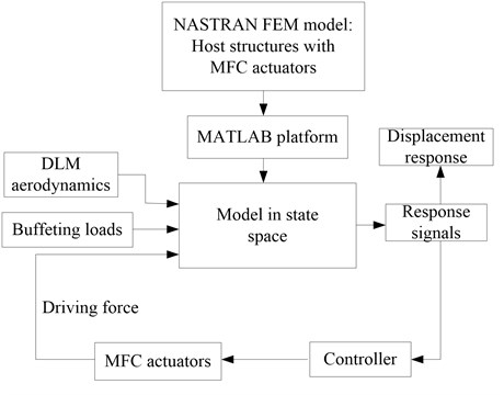
The flow chart of the active buffeting control system is shown in Fig. 3, which depicts the whole scheme of implementing active control to the buffeting responses.
Fig. 2FEM of the vertical tail structure with MFC
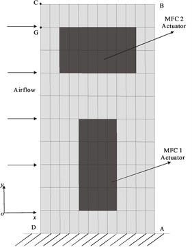
Fig. 3Flow chart of the active buffeting control system
4.1. Validations of the aeroelastic buffeting control models and stability analysis
The electrodynamics of the MFC is modeled by the load simulation method of piezoelectric actuator [18] where the load simulation method was comprehensively proven to be effective and accurate to MFC actuator. Design of control law and buffeting alleviation process are implemented in commercial code MATLAB/SIMULINK. The structural modal data is calculated by NASTRAN software, and the first five truncated modes are selected and the natural frequencies of the tail with the MFC are shown in Table 2.
Table 2The first five natural frequencies of the tail with MFC
Modes (Hz) | Frequencies |
The first bending (Hz) | 5.40 |
The first torsion (Hz) | 25.11 |
The second bending (Hz) | 33.44 |
The second torsion (Hz) | 79.04 |
The third bending (Hz) | 93.30 |
The flutter speed of the tail, calculated by commercial code, is 53.4 m/s. The motion-induced aerodynamic forces, computed by equal pressure element method coded by our team, are transformed and fitted into time domain. Under given initial condition to the system, a dynamic response analysis is conducted. It can be seen from Fig. 4 that the maximum airflow speed of keeping the system stable is 53.4 m/s which is consistent with the result of commercial code. So that validates the motion-induced aerodynamic forces fitted above.
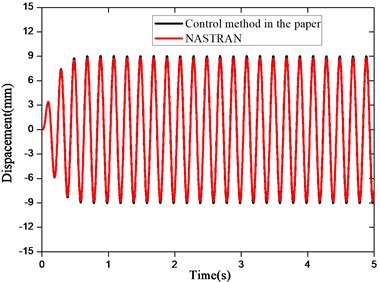
Furthermore, two dynamic responses are performed. One dynamic response analysis is performed by using a sine harmonic excitation force with 5 Hz frequency and 1 N amplitude as the excitation signal based on the control method presented in this paper. Then the piezoelectric driving forces obtained by the above control method are used as the excitation forces for the corresponding model in NASTRAN to perform another dynamic response analysis. As shown in Fig. 5, the displacement responses calculated by the two response analysis methods agree well, which confirms the validity of our control model.
By now, we already have validated aerodynamic force model and the control model to prove our aeroelastic piezoelectric control model. In the flowing, the stability of the buffeting control model will be proved.
Fig. 4Displacement responses in different airflow velocities
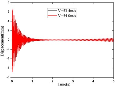
Fig. 5Displacement responses with different methods
It is noted that buffeting occurs below the flutter velocity, thus the aeroelastic system apparently is stable. So, only the stability of the control system needs to be discussed.
Substituting Eq. (20) into Eq. (18) leads to:
where is called the state transition matrix of the close-loop system.
Then the aeroelastic closed-loop state-space equation can be written as:
The complex eigenvalues of the can be obtained through solving the characteristic matrix. If those eigenvalues all have the negative real parts, the stability of this control system is proved. Through the calculation, the eigenvalues of the state matrix of the close-loop system all have the negative real parts at different airflow velocities by using MFC 1 or MFC 2 actuator, which indicates that this buffeting control system is stable. Taking the condition, i.e. 50 m/s and using MFC 1, as an example, as shown in Table 3 where all eigenvalues of the state matrix of the buffeting close-loop system have the negative real parts, which proves the stability of our control system.
4.2. Buffeting responses of the two models
Actually, vertical tail buffeting response is forced vibration because high energy turbulent flows impinge upon the vertical tail. Intense responses occur around low-order modal frequency. Since to get theoretical buffet load is pretty difficult, the load is usually simplified during buffeting simulation in the past. Apparently, the purpose of controlling the vertical tail buffeting responses can be achieved as long as the main low-order modal responses, which in fact have major contributions to buffeting response, are effectively alleviated. Therefore, here a sine harmonic excitation is used as the buffet load whose frequency is close to the first bending modal frequency, which can appropriately represent the typical behavior of the buffet load.
For two different buffeting control law design methods, two corresponding models are developed, respectively. The control law of the model 1 is designed with the consideration of the motion-induced aerodynamic force, while the control law of the model 2 is designed without the consideration. A sine harmonic excitation is used as the buffet load whose frequency is 5 Hz and amplitude is 1 N. Since the buffeting response principally is the first bending modal response, only the MFC 1 is used as the piezoelectric actuator to control the first bending modal response. It is assumed that the peak-to-peak values of control voltages applied to the MFC are 1500 V at all airflow velocities. The buffeting open-loop and closed-loop responses are solved at some typical airflow velocities below the flutter velocity.
Table 3Eigenvalues of the state matrix of the close-loop system
Order | Eigenvalues | Order | Eigenvalues |
1 | –1076.3 | 8 | –162.3 |
2 | –301.9 + 528.0 | 9 | –8.6 + 102.6 |
3 | –301.9 – 528.0 | 10 | –8.6 – 102.6 |
4 | –11.1+ 490.9 | 11 | –56.7 + 82.9 |
5 | –11.1 – 490.9 | 12 | –56.7 – 82.9 |
6 | –114.7 + 267.5 | 13 | –10.9 |
7 | –114.7 – 267.5 | 14 | –26.5 |
Fig. 6 shows that, during the steady state phase, as the airflow velocity increases, the amplitudes of the open-loop buffeting responses decrease gradually. This means that the airflows can improve the system damping. So the higher the airflow velocity is, the stronger the damping effect is.
Fig. 6Buffeting open-loop responses of the vertical tail
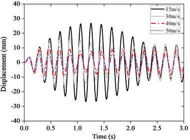
Fig. 7Buffeting closed-loop responses of the model 1
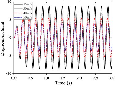
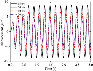
Comparing Fig. 7 (or 8) with Fig. 6, we can see that the amplitudes of the closed-loop buffeting responses of the two models are markedly reduced under active control. In other words, the tail buffeting responses can be effectively alleviated by the LQG control of piezoelectric smart actuator. Afterwards, the influences of the motion-induced aerodynamic forces on the buffeting closed-loop responses are analyzed. As shown in Figs. 7-8, below the flutter velocity, the higher the airflow velocity is, the smaller the amplitude of the buffeting response is. The amplitude of the buffeting response of the model 1 is smaller than that of the model 2 at the same airflow velocity. Therefore, the buffeting responses of the model considering the motion-induced aerodynamic force are much smaller, that is to say its active control effect is much better than model 2.
Fig. 8Buffeting closed-loop responses of the model 2
4.3. Comparisons of the buffeting responses of the two models at different airflow velocities
As we know, vertical tail buffeting is forced vibration because the vertical tail is excited by a random excitation force with certain narrow-band frequencies. In order to examine more general buffet loads, four typical excitation signals are selected as the buffet loads to calculate the buffeting responses. Buffet load 1 is the sine harmonic excitation used in Section 4.2. Buffet load 2 is a white noise signal ranging from 4 to 6 Hz to cover the frequency of first bending mode. And only MFC 1 is adopted in the load case 2. Buffet load 3 is a superposed signal of two sinusoidal signals whose frequencies are respectively close to the frequencies of the first bending mode and the first torsion mode. Buffet load 4 is a white noise signal which has two narrow bands, i.e. one ranging from 4 to 6 Hz and another one ranging from 24 to 26 Hz, so as to cover both the first bending and the first torsion modes. Both the MFC 1 and the MFC 2 are used as actuators in the load cases 3 and 4 so that both the first bending and the first torsion modal responses all can be controlled. The loads and their excitation spectra of the buffet load 2, 3 and 4 are depicted in Fig. 9.
The reduction of the displacement root-mean-square (RMS) at the output point C is defined as , where is the displacement RMS of the buffeting closed-loop response at point C, is the RMS of corresponding open-loop response. In order to compare the buffeting control effects of the two models at different airflow velocities, the reductions of the displacement RMS of the buffeting responses are calculated in four load cases at five typical airflow velocities (below the flutter velocity), i.e. 15, 30, 40, 50 and 53 m/s. It is assumed that the peak-to-peak values of the control voltages applied to the MFC are all 1500 V for each load cases.
It can be seen from Table 4 to Table 7 that the displacement reductions of model 1 are all larger than those of model 2 for four load cases. We may say that the control effect, in terms of displacement reduction, of the model 1 is much better than that of the model 2. The differences of the reductions between model 1 and model 2 is small at lower airflow velocity. As the airflow velocity increases, the difference becomes significant. The larger the airflow velocity is, the more obvious the advantage of control effect of the model 1 is. The differences of the reductions of the two models both reach up to the maximum values at 50 m/s velocity of which is near the flutter velocity for the four load cases. The maximum differences are respectively 17.17 %, 19.41 %, 19.22 % and 20.23 % for the load cases 1, 2, 3 and 4. Therefore, here the influence of the motion-induced aerodynamic force on the active buffeting control effect is small at lower airflow velocity. However, the influence becomes significant at middle or high airflow velocities, and, in that cases, the motion-induced aerodynamic force should be considered in buffeting control law design.
Fig. 9Buffeting load cases
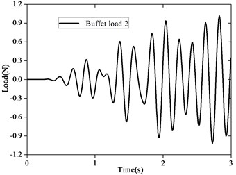
a) Load 2
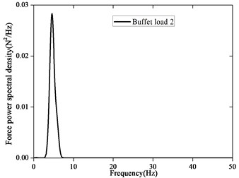
b) Load excitation spectra of the load 2
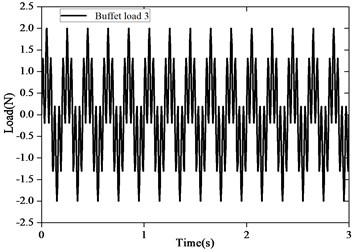
c) Load 3
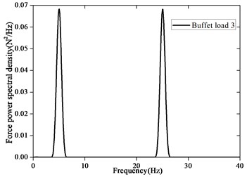
d) Load excitation spectra of the load 3
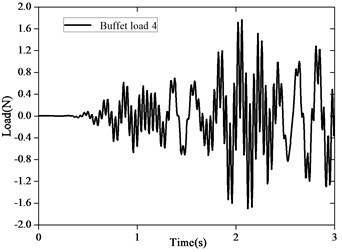
e) Load 4
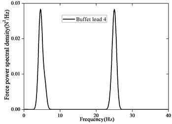
f) Load excitation spectra of the load 4
Table 4Reduction of the displacement RMS (load case 1)
Reduction (%) | (m/s) | |
Model 1 | Model 2 | |
15 | 55.63 | 55.39 |
30 | 45.75 | 39.32 |
40 | 36.99 | 24.32 |
50 | 29.85 | 12.68 |
53 | 22.18 | 9.39 |
4.4. Physical mechanism of the differences between the two models
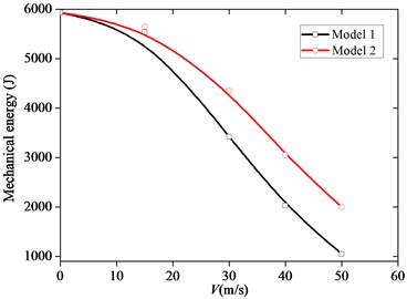
The physical mechanism of the differences between the model 1 and model 2 is discussed based on mechanical energy and its transmission and dissipation during buffeting control. To be representative, it is assumed that the system mechanical energy is zero at initial time. Thus the system mechanical energy at a certain time should be equal to the overall work done by the motion-induced aerodynamic force, excitation force and piezoelectric driving force at this time. Taking the sine harmonic exciting force (load case 1) as buffet load, the energy dissipation of the motion-induced aerodynamic in a cycle during steady-state response phase and the mechanical energy at 1 s are calculated, as shown in Figs. 10-11.
Table 5Reduction of the displacement RMS (load case 2)
Reduction (%) | (m/s) | |
Model 1 | Model 2 | |
15 | 66.69 | 62.89 |
30 | 65.59 | 58.41 |
40 | 60.55 | 48.89 |
50 | 44.26 | 24.85 |
53 | 31.53 | 18.80 |
Table 6Reduction of the displacement RMS (load case 3)
Reduction (%) | (m/s) | |
Model 1 | Model 2 | |
15 | 49.00 | 45.00 |
30 | 46.50 | 37.40 |
40 | 44.95 | 31.79 |
50 | 38.78 | 19.56 |
53 | 31.32 | 16.40 |
Table 7Reduction of the displacement RMS (load case 4)
Reduction (%) | (m/s) | |
Model 1 | Model 2 | |
15 | 62.00 | 59.00 |
30 | 58.10 | 50.00 |
40 | 55.46 | 40.68 |
50 | 44.60 | 24.37 |
53 | 31.30 | 18.74 |
For case of buffeting control, generally speaking, both the motion-induced aerodynamic force and the piezoelectric driving force can improve the damping behavior of the system, which principally are causes of the energy dissipation of the system. Fig. 10 shows that with the increase of the airflow velocity, the motion-induced aerodynamic force does negative work. In other words, the system energy is consumed by the ambient airflow and the energy dissipation gets larger. This means that with the increase of airflow velocity (below the flutter velocity), the damping of the system generated by the motion-induced aerodynamic force is increasingly strong, so the motion-induced aerodynamic force plays a more and more important role in the buffeting alleviation. Thus, the system mechanical energy drops, and the response attenuation becomes faster. Consequently, the amplitudes of the buffeting responses decrease gradually, as shown in Fig. 11. Generally speaking, the principal reason for the buffeting alleviation is that the motion-induced aerodynamic force does negative work and its energy dissipation continuously increases with the increase of the airflow velocity.
The active buffeting control effects of model 1 and model 2 are compared. It can be observed, in Fig. 10, that as the airflow velocity increases, the energy dissipation of the motion-induced aerodynamic force of the model 1 is larger than that of the model 2. Or, the mechanical energy of model 1 is smaller than that of model 2, as shown in Fig. 11. So the amplitudes of the buffeting responses of the model 1 are smaller too. We may say that, below the flutter velocity, the differences of the energy dissipation of the motion-induced aerodynamic force between the two models are small at low airflow velocity. With the increase of the airflow velocity, the energy dissipation of the motion-induced aerodynamic of the model 1 is more than that of the model 2. Moreover, the larger the velocity is, the much more significant the differences are, which might be the main reason for the fact that the amplitudes of the buffeting responses of the model 1 are much smaller. That is to say, the model without consideration of the motion-induced aerodynamic forces in control law design actually weakens the damping of the system, so the response amplitudes of model 1 are smaller than that of model 2. However, at middle and higher airflow velocity below the flutter velocity, the effect of the motion-induced aerodynamic force on the buffeting control gets more obvious. Therefore, in practical applications of aeronautical engineering, the motion-induced aerodynamic force should be considered during buffeting control law design so as to effectively realize the buffeting alleviation.
Fig. 10The energy dissipation of the motion-induced aerodynamic force of the two models
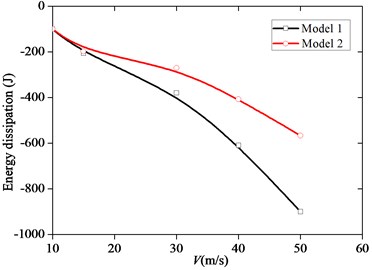
Fig. 11The system mechanical energy of the two models
5. Conclusions
1) The motion-induced aerodynamic forces can influence the buffeting open-loop and closed-loop responses. Below the flutter velocity, as the velocity rises, the amplitude of the buffeting response gets smaller because the damping of the system generated by the motion-induced aerodynamic force is increasingly strong.
2) For buffeting control below the flutter velocity, the differences of the buffeting responses between the two models are small at lower airflow velocity. As the airflow velocity increases, the amplitudes of the buffeting response of the model 1 is much smaller than model 2. The larger the velocity is, the more significant the differences are. Therefore, the motion-induced aerodynamic force should be considered during buffeting control law design.
3) Below the flutter velocity, with the increase of the airflow velocity, the energy dissipation of the motion-induced aerodynamic force of model 1 is larger than that of model 2. Moreover, the larger the velocity is, the much more significant the differences are, which is the main reason for the fact that the buffeting control effect of the model considering the motion-induced aerodynamic force is much better.
References
-
Meyn L. A., James K. D. Full-scale wind tunnel studies of F/A-18 tail buffet. Journal of Aircraft, Vol. 33, Issue 3, 1996, p. 589-595.
-
Anderson W. D., Patel S. R., Black C. L. Low-speed wind tunnel buffet testing on the F-22. Journal of Aircraft, Vol. 43, Issue 4, 2006, p. 879-885.
-
Lee B. H. K., Brown D. Wind-tunnel studies of F/A-18 tail buffet. Journal of Aircraft, Vol. 29, Issue 1, 1992, p. 146-152.
-
Hebbar S. K., Platzer M. F., Frink Jr. W. D. Effect of Leading-edge extension fences on the vortex wake of an F/A-18 model. Journal of Aircraft, Vol. 32, Issue 3, 1995, p. 680-682.
-
Lee B. H. K. Vertical tail buffeting of fighter aircraft. Progress in Aerospace Sciences, Vol. 36, Issues 3-4, 2000, p. 193-279.
-
Bean D. E., Wood N. J. Experimental investigation of twin-fin buffeting and suppression. Journal of Aircraft, Vol. 33, Issue 4, 1996, p. 761-767.
-
Sheta E. F., Harrand V. J., Huttsell L. J. Active vertical flow control for alleviation of twin-tail buffet of generic fighter aircraft. Journal of Fluids and Structures, Vol. 15, Issue 6, 2001, p. 769-789.
-
Rock S. M., Ashley H., Digumarthi R., Chaney K. Active control for fin buffet alleviation. AIAA Guidance, Navigation and Control Conference, 1993, p. 1051-1056.
-
Breitsamter C. Aerodynamic active control for fin-buffet load alleviation. Journal of Aircraft, Vol. 42, Issue 5, 2005, p. 1252-1263.
-
Hauch R. M., Jacobs J. H., Dima C., Ravindra K. Reduction of vertical tail buffet response using active control. Journal of Aircraft, Vol. 33, Issue 3, 1996, p. 617-622.
-
Nitzsche F., Zimcik D. G., Ryall T. G., Moses R. W., Henderson D. A. Closed-loop control tests for vertical fin buffeting alleviation using strain actuation. Journal of Guidance, Control, and Dynamics, Vol. 24, Issue 4, 2001, p. 855-857.
-
Sheta E. F., Moses R. W., Huttsell L. J. Active smart material control system for buffet alleviation. Journal of Sound and Vibration, Vol. 292, Issues 3-5, 2006, p. 854-868.
-
Zhao Y. H., Hu H. Y. Active control of vertical tail buffeting by piezoelectric actuators. Journal of Aircraft, Vol. 46, Issue 4, 2009, p. 1167-1175.
-
Wang W., Zhang X. P., Yang Z. C., Li B., Liu J. L. Piezoelectric active control for tail buffeting at high angle of attack. Science China Technological Sciences, Vol. 55, Issue 10, 2012, p. 2694-2699.
-
Wickramasinghe V. K., Chen Y., Zimcik D. G. Experimental evaluation of an advanced buffet suppression system on full-scale F/A-18 fin. Journal of Aircraft, Vol. 44, Issue 3, 2007, p. 733-740.
-
Gao L., Lu Q. Q., Fei F., Liu L. W., Liu Y. J., Leng J. S. Active vibration control based on piezoelectric smart composite. Smart Materials and Structures, Vol. 22, 2013, p. 125032.
-
Lee B. H. K. Statistical analysis of wing/fin buffeting response. Progress in Aerospace Sciences, Vol. 38, Issues 4-5, 2002, p. 305-345.
-
Li M., Chen W. M., Wang M. C., Jia L. J. A load simulation method of piezoelectric actuator in FEM for smart structures. Science in China Series E: Technological Science, Vol. 52, Issue 9, 2009, p. 2576-2584.
-
Albano E., Rodden W. P. A doublet-lattice method for calculating lift distributions of oscillating surfaces in subsonic flow. AIAA Journal, Vol. 7, Issue 2, 1969, p. 279-285.
-
Song Z. G., Li F. M. Aerothermoelastic analysis and active flutter control of supersonic composite laminated cylindrical shells. Composite Structures, Vol. 106, 2013, p. 653-660.
About this article

This study was co-supported by the State Key Program of National Natural Science Foundation of China (Grant No. 11232012) and the National Natural Science Foundation of China (Grant No. 11372320).
