Abstract
In order to study the effect of airflow on the acoustic attenuation performance of reactive muffler, firstly, the formulas of wavenumber, transfer matrix method and three point method were deduced in the case of uniform flow. Then, the differences between transfer matrix method and three point method were compared based on the results of finite element method (FEM), for the no-flow, uniform flow and non-uniform flow three different cases. The results showed that both the transfer matrix method and three point method can accurately calculate the transmission loss (TL) of muffler under no-flow and uniform flow conditions. But, for the non-uniform flow case, both the results calculated by the two methods above have deviations on account of the complexity of flow field and the limitations of calculation methods. In addition, negative values even appear in the low frequency range. Finally, comparative study about the effect of uniform flow and non-uniform flow on the acoustic attenuation performance of muffler was made. Results showed that the difference of the effect of uniform flow and non-uniform flow on the acoustic attenuation performances is little when the airflow regenerated noise is ignored and the existence of airflow has little effect on the acoustic attenuation performance of reactive muffler. Therefore, the effect of airflow on the acoustic attenuation performance can be neglected during the initial phase of muffler design.
1. Introduction
Mufflers are widely used in mechanical systems and obviously affect the comprehensive property of mechanical systems [1-4]. Its acoustic attenuation performance has been researched by many scholars. Early studies are mostly based on the assumption that the medium inside the muffler is static ideal gas [5-9]. But, this assumption is not consistent with the actual situation. In fact, mufflers are often used to attenuate the noise from fluid machines, the existence of high velocity airflow may affect the propagation and attenuation of sound wave. Therefore, some scholars discussed the acoustic attenuation performance of muffler under the non-static gas condition. The flow field was assumed to be uniform, that is, the fluid motion of every part has same effect on the propagation and attenuation of sound wave, and the wave equation was deduced in this case. Then, the effect of uniform flow on the acoustic attenuation performance of muffler was explored by experiment, theoretical analysis and numerical simulation [10-17]. Though the assumption above simplified the flow field inside the muffler and the research, the effect of practical flow field on the propagation and attenuation of sound wave has not been truly reflected. Actually, flow field inside the muffler is very complex and the effects of airflow at all places are not consistent. Thus, the prediction method of acoustic attenuation performance for the muffler with non-uniform flow was discussed. Consequently, the results become closer to the truth [18-21].
The above researches have obtained a lot of achievements and provided references for the muffler design. Whereas, in the case of uniform flow, negative values appear on the TL curves in Refs. [16-18] on the condition that the airflow regenerated noise is not considered, which is not consistent with the truth. Furthermore, most of the references adopt transfer matrix method to calculate the TL values of muffler with flow, but two different boundary conditions must be set and need double-calculation, which is complex and time-consuming. What is more, the assumptions of uniform flow and non-uniform flow both have their advantages and disadvantages, but not much attention has been given to the differences between the two.
The present work aims at discussing the problems above. The remainder of this paper develops as follows: first, in Section 2, the calculation formulas of wavenumber, transfer matrix method and three point method were deduced under uniform flow condition. Thereafter, in Section 3, the differences between transfer matrix method and three point method were compared. Next, in Section 4, the effects of uniform flow and non-uniform flow on the acoustic attenuation performance of reactive muffler were studied by FEM. Finally, Section 5 concludes the paper.
2. Theory
2.1. Wavenumber under uniform flow condition
Along the x direction, the wave equation, which contains velocity gradient and temperature gradient, can be written as [22]:
where , , are the components of fluctuation velocity, is the velocity of uniform flow, and are the sound velocity and air density, respectively. is the sound pressure, is the time, , , are the three directions of coordinate axis, respectively.
When the flow field is uniform and isothermal, , and the wave equation can be rewritten as:
The expression of sound pressure along the positive direction is:
where , , are the wavenumbers along , , directions, respectively; , are the incident wave and reflected wave along the direction, respectively; , are the incident wave and reflected wave along the direction, respectively.
Submitting Eq. (3) into Eq. (2) yields:
where, is the wavenumber in the case of no-flow, is the angular frequency, is the Mach number, is the wavenumber of the uniform flow. When the sound waves propagate along direction in the form of plane wave, , , Then, the axial wavenumbers and can be written as: , , “–” represents direction.
2.2. Transfer matrix method
Fig. 1(a) shows the sketch map of TL measurement. In the case of uniform flow, the sound pressures of the four measuring points can be expressed as:
where, , are the complex sound pressures of point 1 and point 2, respectively. , are the complex sound pressures of point 3 and point 4, respectively. , are the incident sound pressure and reflected sound pressure of cross-section -, respectively; , are the incident sound pressure and reflected sound pressure of cross-section -, respectively; , are the distances between point 1, point 2 and the cross-section -, respectively; , are the distances between point 3, point 4 and the cross-section -, respectively.
By solving the Eq. (5), , , and can be written as:
where is the distance between measuring point 1 and measuring point 2; is the distance between measuring point 3 and measuring point 4.
The transfer matrix of muffler can be expressed as:
where , are the sound pressure and particle velocity of cross-section -, respectively; , are the sound pressure and particle velocity of cross-section -, respectively. , , and represent the four-pole parameters.
Assuming the sound waves in inlet and outlet pipes propagate in the form of plane wave, the sound pressures and particle velocities of cross-sections - and - are given by:
In order to obtain the four-pole parameters, two boundary conditions must be set.
Boundary condition 1:
Boundary condition 2:
The four-pole parameters derived from Eqs. (9)-(10) can be written as:
Fig. 1Geometry of mufflers
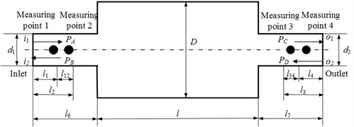
a) Sketch map of transmission loss measurement
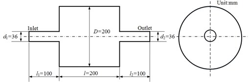
b) Coaxial expansion muffler
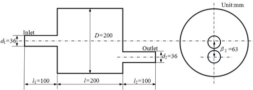
c) Non-coaxial expansion muffler
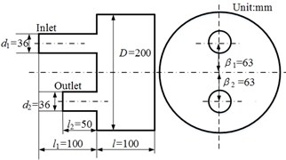
d) Reversing chamber muffler
Submitting Eq. (8) into Eq. (11) yields:
where , and , are the incident sound pressures and reflected sound pressures of inlet and outlet pipes under boundary condition 1; , and , are the incident sound pressures and reflected sound pressures of inlet and outlet pipes under boundary condition 2.
The TL calculated by four-pole parameters can be written as:
Submitting Eq. (12) into Eq. (13) gives:
2.3. Three point method
Assuming the sound waves in inlet and outlet pipes propagate in the form of plane wave and the outlet pipe has an anechoic termination, that is the reflected wave 0. Then, the sound wave in the outlet pipe only contains incident wave, that is ; the sound wave in the inlet pipe contains incident wave as well as reflected wave. Hence, the sound pressures at point 1 and point 2 can be written as [23]:
can be obtained by solving Eq. (15):
The TL is defined as the difference between the incoming sound power level and the outgoing sound power level, therefore, the TL calculated by three point method can be expressed as:
where and are the cross-sectional areas of the inlet and outlet pipes, respectively. If , the formula of three point method can be rewritten as:
3. Comparison of transfer matrix method and three point method
Under the no-flow, uniform flow and non-uniform flow three different conditions, the computational accuracy of transfer matrix method and three point method was compared. In addition, the uniform flow is modeled by applying a zero potential value to the nodes of outlet surface and a constant flow velocity on the inlet surface to provide a fixed flow rate through the model during the acoustic field calculation, so the turbulence was not considered. However, the non-uniform flow is modeled by mapping the flow field data calculated by CFD software Fluent® to the nodes of acoustical mesh. In this case, the - two-equation turbulence model was chosen, so the turbulence was considered.
Fig. 2(a) and Fig. 2(b) are the FEM models of flow field calculation and acoustic field calculation, respectively. Both the two FEM models adopt hexahedron mesh and the mesh sizes of the two FEM models are 4 mm and 8 mm, respectively. In addition, the material is the air at normal pressure and temperature for all the calculations. For the flow field calculation, the inlet is set as velocity boundary condition, the outlet is set as pressure outlet and the pressure is zero relative to atmospheric pressure, the wall is smooth. For the acoustic field calculation, the inlet is set as unit vibration velocity, the outlet is set as anechoic termination for the three point method and the acoustic impedance of outlet is set as two different values for the transfer matrix method.
In order to calculate the TL, firstly, the sound pressures of measuring points should be obtained by FEM. Then, bringing the sound pressures into the formulas of three point method and transfer matrix method to calculate the TL. And the flowchart of TL calculation is shown in Fig. 3.
Fig. 2FEM models
a)
b)
Fig. 3Flowchart of TL calculation
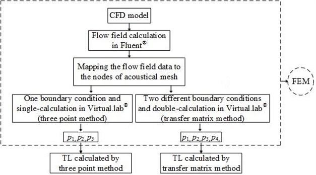
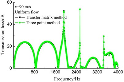
Fig. 4(a) and 4(b) shows the TL curves of coaxial expansion muffler under no-flow and uniform flow of 90 m/s conditions, respectively. And the geometry of coaxial expansion muffler is shown in Fig. 1(b). It can be observed that the TL curves overlap completely for the two calculation methods no matter the airflow velocity is zero or uniform flow of 90 m/s, which explains that both the two methods above can accurately calculate the TL values of muffler under no-flow and uniform flow conditions. In addition, it should be noted that negative values appear on the TL curves of mufflers with uniform flow in Refs. [16-18] on the condition that airflow regenerated noise is ignored, which is not consistent with the theory. However, it can be seen that no negative values appear on the TL curves calculated by the transfer matrix method and three point method in this paper, as shown in Fig. 4(b), which fully shows that the calculation error of TL is eliminated and the computational accuracy of TL is improved in the case of uniform flow assumption.
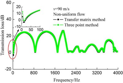
In Fig. 4(c), the TL curves calculated by transfer matrix method and three point method were compared for the non-uniform flow case. Similar with the above cases, two curves almost coincide exactly, but negative values appear in the frequency region of 0-50 Hz.
In order to explore the reasons of the phenomenon mentioned above, the TL curves of the coaxial expansion muffler under uniform flow and non-uniform flow conditions were made a further comparison.
As shown in Fig. 5, no matter the results are calculated by transfer matrix method or three point method, differences between the uniform flow results and non-uniform flow results are always existing. Compared with the uniform flow results, non-uniform results significantly decrease at the peaks except the phenomenon mentioned above.
Fig. 4Comparison of transfer matrix method and three point method
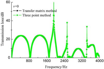
a)0
b) Uniform flow
c) Non-uniform flow
Fig. 5Transmission loss comparison
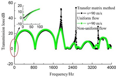
a) Transfer matrix method
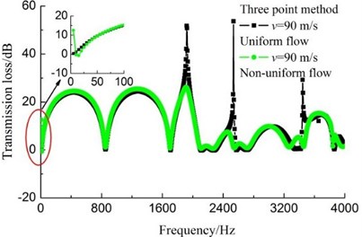
b) Three point method
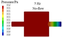
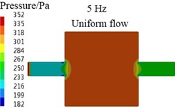
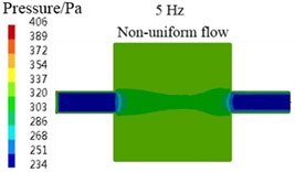
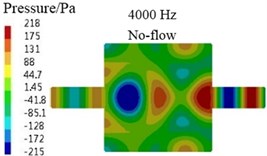
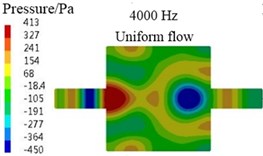
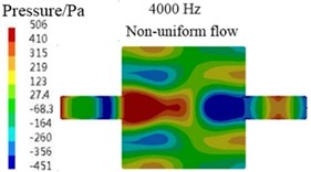
For the above differences, the main reason is the limitation of algorithm, for example, for the transfer matrix method, , and , in the Eq. (7) are the average sound pressures and average particle velocities of cross-sections - and -, respectively. For the plane wave, the sound pressures and particle velocities of arbitrary two points in a same cross-section are the equal. So, the value of any point in the cross-section can be seen as the average value and selected to calculate the values of , , and . At last, the results of , and , equal to the average values of cross-sections - and -, respectively. Therefore, the TL values calculated by transfer matrix method are accurate for the plane wave case. In Fig. 6(a), (b), (d), (e), the sound pressure contours at 5 Hz and 4000 Hz are presented for the coaxial expansion muffler under no-flow and uniform flow conditions, respectively. It can be observed that the sound waves propagate in the form of plane wave in the inlet and outlet pipes, actually, in the whole analysis frequency region, the sound waves in the inlet and outlet pipes always propagate in the shape of plane wave. Hence, the transfer matrix method in this paper can be used to predict the TL values of muffler under no-flow and uniform flow conditions.
Fig. 6Sound pressure contours
a)
b)
c)
d)
e)
f)
Fig. 7Velocity contours
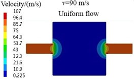
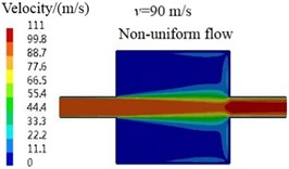
However, for the non-uniform flow case, the sound waves in the inlet and outlet pipes are not strict plane wave, as shown in Fig. 6(c) and (f), which can be explained by the velocity contours in Fig. 7. It is observed that the airflow velocities in the inlet and outlet pipes are uniform and equal under uniform flow condition, so the effects of airflow at all places on the sound waves propagation are consistent and the sound waves propagate in the form of plane wave in the inlet and outlet pipes. But, for the non-uniform flow case, because the wall boundary condition was considered in the flow field calculation and the velocity fluctuation caused by the abrupt change of cross-section is large, the airflow velocities in the inlet and outlet pipes are not uniform and equal. Consequently, the sound waves in the inlet and outlet pipes are not strict plane wave.
Furthermore, the in Eq. (5) is the specific value of and . As mentioned above, the airflow in the inlet and outlet pipes are not uniform for the non-uniform flow case, that is, the Mach numbers in all parts of the pipes are not entirely equal. Therefore, the TL values calculated by the which still equals to the specific value of and are not accurate.
Because of the existence of above reasons, the TL values calculated by transfer matrix method generate errors for the non-uniform flow case, negative values even appear in the low frequency. Similarly, three point method has the same problems, so they will not be mentioned in this article.
In conclusion, both the transfer matrix method and three point method can accurately calculate the TL of muffler under no-flow and uniform flow conditions. Just for the non-uniform flow case, the errors of TL values still exist on account of the complexity of airflow and the limitation of algorithm. Synthetically consider the advantages and disadvantages of the two methods above, three point method was used for the following calculations for purpose of reducing the calculation and saving the computing time.
4. Effects of airflow
In order to study the effects of uniform flow and non-uniform flow on the acoustic attenuation performance of muffler, taking the expansion chamber muffler and reversing chamber muffler two kinds of simple reactive muffler and a complex car muffler as examples, comparative study was made when the airflow regenerated noise is ignored.
4.1. Simple reactive muffler
Fig. 8(a) shows the TL curves of non-coaxial expansion muffler under different airflow velocities conditions, and its geometry is shown in Fig. 1(c). It is observed that the TL curve almost has no change as the increase of airflow velocity for the muffler with uniform flow. While, for the non-uniform flow case, even though the TL curves nearly overlap completely in the frequency range of 0-1800 Hz and the difference of TL curves is small in the frequency range of 3400-4000 Hz, the change is still very obvious in the frequency range of 1800-3400 Hz, especially in the frequency ranges of 2600-2800 Hz and 3000-3400 Hz. The main reason is that the inlet and outlet pipes are not coaxial, the high-speed airflow ejected from inlet pipe strikes the opposite wall and forms strong reflow. Then the reflow air mixes with the low speed air in the muffler and forms strong turbulence which leads to large velocity fluctuation [24]. As a result, the propagation of sound wave were affected more largely.
Fig. 8Transmission loss curves
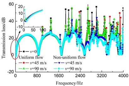
a) Non-coaxial expansion muffler
b) Reversing chamber muffler
Because the higher order modes were suppressed effectively, the acoustic attenuation performance of muffler (0, 0.063) had a significant enhancement in the medium-high frequency range [25]. Whereas, the effect of airflow has not been considered in Ref. [25]. It can be seen from the above analysis, the existence of airflow did not destroy the good acoustic attenuation performance of this type of muffler on the condition that the airflow regenerated noise is ignored, no matter the airflow is uniform or non-uniform.
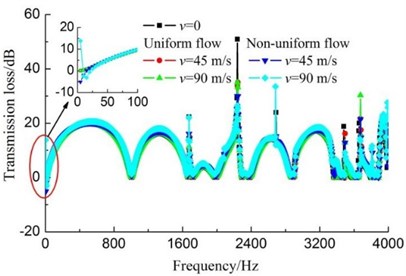
In Fig. 8(b), the TL curves of reversing chamber muffler under different airflow velocities conditions are presented, and the geometry of the reversing chamber muffler is shown in Fig. 1(d). Similar with the expansion muffler, the airflow has little effect on the acoustic attenuation performance of reversing chamber muffler and the difference between uniform flow and non-uniform flow is little too.
4.2. Complex car muffler
In order to make the conclusion more universal, further study about the effect of airflow on the acoustic attenuation performance of complex car muffler was made. The geometry of the car muffler is shown in Fig. 9.
Fig. 10 presents the TL curves of the complex car muffler under different airflow velocities conditions. Similar conclusions have also been obtained, the acoustic attenuation performance of the complex car muffler was slightly affected by the airflow. The existence of airflow has not destroyed the good acoustic attenuation performance of the car muffler. Furthermore, it can be observed that the average TL of the car muffler gradually decreases with the increase of airflow velocity, but the reduction is tiny, as indicated in Table 1. When the inlet airflow velocity is 90 m/s, the TL values of the car muffler only reduce 0.56 dB and 2.48 dB for the uniform flow and non-uniform flow cases, respectively. In addition, the change rate of TL decreases as airflow velocity increases.
Fig. 9Geometry of a complex car muffler
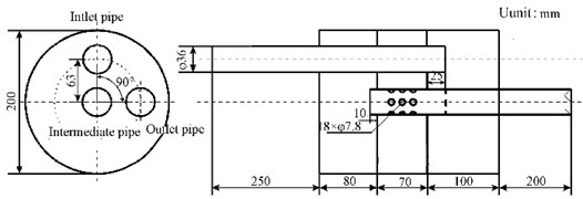
Fig. 10Transmission loss curves of the complex car muffler
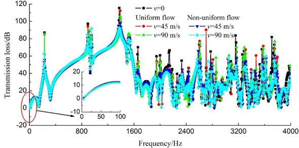
Table 1Transmission loss variation of a car muffler with different airflow velocities
Flow velocity | Average transmission loss/dB (uniform flow) | Average transmission loss/dB (non-uniform flow) |
0 | 38.75 | 38.75 |
30 m/s | 38.35 | 37.59 |
45 m/s | 38.36 | 37.22 |
60 m/s | 38.28 | 36.93 |
75 m/s | 38.20 | 36.51 |
90 m/s | 38.19 | 36.27 |
Note: The inlet airflow velocity is 90 m/s | ||
5. Conclusions
Both the transfer matrix method and three point method can accurately calculate the TL values of muffler under no-flow and uniform flow conditions. While, for the non-uniform flow case, both the results calculated by the two methods above exist errors, negative values even appear in the low frequency, because of the complexity of airflow and the limitation of calculation method.
The difference of the effect of uniform flow and non-uniform flow on the acoustic attenuation performances is little when the airflow regenerated noise is ignored. Furthermore, both the acoustic attenuation performances of simple reactive muffler and complex car muffler are affected slightly by the airflow in the case of 0.3. When the inlet airflow velocity is 90 m/s, the TL values of the complex car muffler only reduce 0.56 dB and 2.48 dB for the uniform flow and non-uniform flow cases, respectively. In addition, the change rate of TL decreases as the airflow velocity increases. Therefore, the effect of airflow on the acoustic attenuation performance can be ignored during the initial phase of muffler design when the airflow regenerated noise is ignored.
References
-
Yasuda T., Wu C. Q., Nakagawa N., Nagamura K. Predictions and experimental studies of the tail pipe noise of an automotive muffler using a one dimensional CFD model. Applied Acoustics, Vol. 71, Issue 8, 2010, p. 701-707.
-
Yasuda T., Wu C. Q., Nakagawa N., Nagamura K. Studies on an automobile muffler with the acoustic characteristic of low-pass filter and Helmholtz resonator. Applied Acoustics, Vol. 74, Issue 1, 2013, p. 49-57.
-
Oh S., Wang S., Cho S. Development of energy efficiency design map based on acoustic resonance frequency of suction muffler in compressor. Applied Energy, Vol. 150, 2015, p. 233-244.
-
Nagarjuna K., Sreenivas K. Noise reduction in a reciprocating compressor by optimizing the suction muffler. International Journal of Engineering Trends and Technology, Vol. 16, Issue 6, 2014, p. 276-282.
-
Banerjee S., Jacobi A. M. Transmission loss analysis of single-inlet/double-outlet (SIDO) and double-inlet/single-outlet (DISO) circular chamber mufflers by using Green’s function method. Applied Acoustics, Vol. 74, Issue 12, 2013, p. 1499-1510.
-
Venkatesham B., Tiwari M., Munjal M. L. Transmission loss analysis of rectangular expansion chamber with arbitrary location of inlet/outlet by means of Green’s functions. Journal of Sound and Vibration, Vol. 323, Issues 3-5, 2009, p. 1032-1044.
-
Mimani A., Munjal M. L. 3-D acoustic analysis of elliptical chamber mufflers having an end-inlet and a side-outlet: an impedance matrix approach. Wave Motion, Vol. 49, Issue 2, 2012, p. 271-295.
-
Chaitanya P., Munjal M. L. Effect of wall thickness on the end corrections of the extended inlet and outlet of a double-tuned expansion chamber. Applied Acoustics, Vol. 72, Issue 1, 2011, p. 65-70.
-
Kar T., Munjal M. L. Generalized analysis of a muffler with any number of interacting ducts. Journal of Sound and Vibration, Vol. 285, Issue 3, 2005, p. 585-596.
-
Fang Z., Ji Z. L. Numerical mode matching approach for acoustic attenuation predictions of double-chamber perforated tube dissipative silencers with mean flow. Journal of Computational Acoustics, Vol. 22, Issue 2, 2014, p. 1-15.
-
Chaitanya P., Munjal M. L. Experimental validation of the 1-D acoustical model for conical concentric tube resonators with moving medium. Noise Control Engineering Journal, Vol. 59, Issue 2, 2011, p. 158-164.
-
Kirby R. Analytic mode matching for a circular dissipative silencer containing mean flow and a perforated pipe. The Journal of the Acoustical Society of America, Vol. 122, Issue 6, 2007, p. 3471-3482.
-
Munjal M. L. Plane wave analysis of side inlet/outlet chamber mufflers with mean flow. Applied Acoustics, Vol. 52, Issue 2, 1997, p. 165-175.
-
Singh N. K., Rubini P. A. Large eddy simulation of acoustic pulse propagation and turbulent flow interaction in expansion muffler. Applied Acoustics, Vol. 98, 2015, p. 6-19.
-
Lee S. H., Ih J. G. Effect of non-uniform perforation in the long concentric resonator on transmission loss and back pressure. Journal of Sound and Vibration, Vol. 311, Issues 1-2, 2008, p. 280-296.
-
Ji Z. L., Ma Q., Zhang Z. H. Application of boundary element method to prediction acoustic performance of expansion chamber mufflers with mean flow. Journal of Sound and Vibration, Vol. 173, Issue 1, 1994, p. 57-71.
-
Chiang D. M., Chen W. H. Transmission loss analysis of expansion chamber mufflers with mean flow. Journal of the Chinese Society of Mechanical Engineers, Vol. 28, Issue 1, 2007, p. 3-11, (in Chinese).
-
Singh R., Katra T. Development of an impulse technique for measurement of muffler characteristics. Journal of Sound and Vibration, Vol. 56, Issue 2, 1978, p. 279-298.
-
Lee L., Wu T. W., Zhang P. A dual-reciprocity method for acoustic radiation in a subsonic non-uniform. Engineering Analysis with Boundary Elements, Vol. 13, Issue 4, 1994, p. 365-370.
-
Ji Z. L., Zhang Z. H., Ma Q. A boundary element scheme for evaluation of four-pole parameters of ducts and mufflers with low Mach number non-uniform flow. Journal of Sound and Vibration, Vol. 185, Issue 1, 1995, p. 107-117.
-
Wang X. R., Ji Z. L. Boundary element analysis of four-pole parameters and transmission loss of silencer with flow. Chinese Journal of Computational Physics, Vol. 24, Issue 6, 2007, p. 717-724, (in Chinese).
-
Qiao W. Y. Aircraft Engine Pneumatic Acoustics. Original Edition, Beijing University of Aeronautics and Astronautics Press, Beijing, 2010, (in Chinese).
-
Wu T. W., Wan G. C. Muffler performance studies using a direct mixed-body boundary element method and a three-point method for evaluating transmission loss. Journal of Vibration and Acoustics, Transactions of the ASME, Vol. 118, Issue 3, 1996, p. 479-484.
-
Chu Z. G., Kuang F., Gao X. X., Kang R. C. Effects of outlet pipe transition circular arc on properties of reactive muffler and its application. Transactions of the Chinese Society of Agricultural Engineering, Vol. 31, Issue 6, 2015, p. 105-112, (in Chinese).
-
Chu Z. G., Lu X. H., Shen L. B., Gao X. X., Zhang J. Y. Effects of acoustic modes in chamber on acoustic attenuation characteristics of reactive silencing elements. Chinese Internal Combustion Engine Engineering, http://www.cnki.net/kcms/detail/31.1255.TK.20140818.0905.001.html, (in Chinese).
About this article

This work was supported by Chongqing Significant Application and Development Planning Project (No. cstc2015yykfc60003) and National Natural Science Foundation of China (51275540, 51275542).
