Abstract
In this paper, in order to investigate the natural modes of the rotor system of turbocharger, the analytical model of floating-ring bearing, the FEM and modal test technology were employed. Firstly, based on Reynolds equations of the dynamic oil layer of floating-ring bearing, the oil layer pressure was obtained by using the finite difference algorithm. Then the stiffness coefficients and damping coefficients were calculated by using integration method. Next the FEM model of rotor system with supporting stiffness of floating-ring bearings was established. Then the natural modes of rotor system were simulated with considering the oil layer stiffness of the floating-ring bearings and the rotor’s rotating speeds. Lastly, the natural modes were identified with modal test technology and furthermore the FEM calculation results were verified. The investigation shows that the oil layer stiffness of the floating-ring bearings and rotating speeds of the rotor have great influences on vibration modes of the rotor system.
1. Introduction
Turbocharger is a component which can improve the burning efficiency and reduce the fuel consumption by increasing the density of the air in the cylinder and so is now widely used in the engines. Turbocharger has a high rotational speed and its working speeds are between 60,000 r/min and 250,000 r/min. Its core component is a rotor system with double disc and double support. When the rotor rotates at high speed, not only does the resonant vibration of the rotor occur, but also do the oil whip and oil whirl of the floating-ring bearings appear. So the investigation on the natural modes of rotor system, including impeller, the rotor shaft, the floating-ring, the oil layer bearing and turbine, is necessary and is of great importance for improving turbocharger’s stability and reliability.
The different types of vibration problems of rotor system have been studied [1-10]. For example, Ying J. [9] calculated the bearing oil-film force by a database method and studied the influence of both pad offset and preload. Huang R. [10] established a rotor dynamic model of a vehicular turbocharger considering seal structures and gas flow-exciting and analyzed the influences of accelerating on the transient response of the bearing – rotor system. Li G. J. [11] studied the dynamics modeling and analysis method of rotor system. In his research, in order to prove the validity of the method of modeling and the accuracy of the analysis results, the theoretical calculation and test check was combined, and according to the theory and test methods, a new visualization software which was special for the turbocharger was developed. Li H. L. [12] firstly established the mathematical model to find turbocharger critical speed, the second and third critical speeds of rotor system were calculated by transfer matrix method and Riccati transfer matrix method. Then the turbocharger dynamic differential equations without floating-ring and including floating-ring were established and the motion stability and the phenomenon of limit cycle that is caused by oil whip was analyzed based on the Hopf bifurcation theory. Furthermore, the influence of structure parameters on the limit cycle was also analyzed. Ashtekar A. and Zhu L. [13, 14] established a double overhung flexible rotor dynamic model of turbocharger by using the transfer matrix method, and modal analysis of the whole system was carried out via the linearized oil film force, and then the influence of the supporting point and supporting stiffness on nature mode of rotor were investigated. In this paper, the influence of double oil film of floating-ring bearing nonlinear effect on the rotor of the turbocharger system will be investigated through numerical method combined with Capone oil force model. The main research work of this paper is to establish the analytical model of floating-ring bearing and the FEM method of the rotor system, and then the natural modes of the rotor system is calculated. And the modal results under no rotating speed are verified by using the experimental modal test technology.
2. Dynamical model of floating-ring bearing
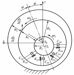
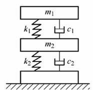
The rotor system of turbocharger is supported with two floating-ring bearings, and its dynamical model is shown as Fig. 1.
Fig. 1Dynamical model of floating-ring bearing
a)
b)
In Fig. 1, , , and are stiffness coefficients of oil layer, , , and are damping coefficients of oil layer; is radius of rotor shaft, is radius of floating-ring; and are rotational angular velocity of floating-ring and rotor shaft respectively. and are rotor system mass and floating-ring mass respectively. The stiffness and damping of floating-ring bearings are related to the inner hydrodynamic oil film and the outer hydrodynamic oil film of floating-ring bearing.
Take the infinitesimal body of oil film as the force analysis object, and use the flow continuity equation and Newton’s law of viscosity. Then the following mathematical expression of Reynolds equation can be derived as following Eq. (1):
where is radius of bearing (unit, m); is pressure of oil layer (unit, Pa); is the oil viscosity (unit, Ns/m2); is axial coordinate of bearing and its origin is located at middle of bearing width; is time (unit, s).
Let the partial differential Eq. (1) be discretized into a differential equation, and organize as following:
where , , , , and are expressed as following:
The Eq. (1) could be written as the following matrix:
where the matrix and vector are the function of , , and , and further the matrix is a high order, large and sparse matrix.
There are many ways for solving the differential Eq. (9). At present the most commonly used method is super-relaxation iteration method. The super-relaxation iteration method has advantages of wide applicable scope, process stability, and simple programming, etc. Its calculation process is as follows:
1) Preset the radius , width , initial eccentricity ratio and deviation angle , then calculate , , , , and (1,…, 1, 1,…, 1), according to the Eq. (3) to Eq. (8).
2) Preset the initial value and the boundary value:
3) Calculate the super-relaxation factor .
4) Solve the differential equation with the super-relaxation iteration method.
Firstly, write the Eq. (2) into following form:
Then assign the given value of the boundary conditions to the pressure on the boundary nodes, and estimate the pressure value of each node in domain as the first approximation (1,…, 1, 1,…, 1), and calculate line by line according to the order of 1, 2, 3,…, . But on each line, the calculation is carried out from the starting side to stop edge, and scanning according to the order of 1, 2, 3,…, , in order to facilitate them to be incorporated into the boundary conditions of Reynolds equation. Once the node’s pressure value is calculated out, and the original pressure value will be replaced by the new pressure value. Until all inner nodes’ pressure is calculated out, the second approximate distribution will be obtained. The second solution is better than the first approximation precision. Then do calculations again from the starting side to stop edge, get a more accurate approximation for the third distribution , and abort the iterative process. Fig. 2 and Fig. 3 are calculation results of inner oil layer pressure distribution and outer oil layer pressure distribution respectively.
Fig. 2Simulation result for inner oil layer pressure
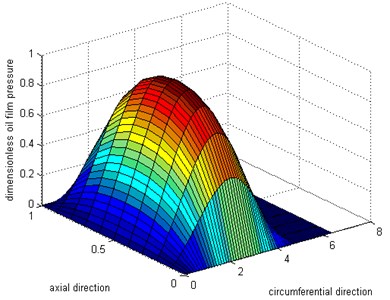
Fig. 3Simulation result for outer oil layer pressure
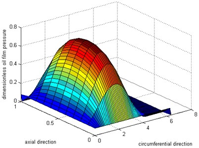
According to Fig. 2 and Fig. 3, we can find out that inner oil layer pressure is slightly larger than outer oil layer pressure. There are two reasons for causing this phenomenon: one is that the rotating speed of the rotor is higher than the floating and the other reason is that the wedge area of inner oil layer is smaller than the wedge area of outer oil layer, shown as Fig. 4.
Fig. 4Geometric analysis for rotor
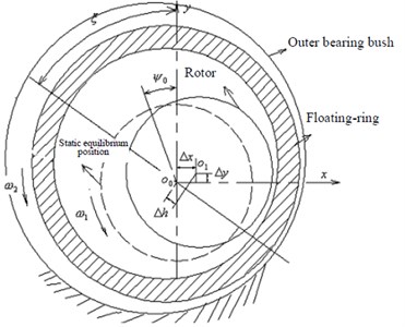
Based on the obtained oil layer pressure results, the stiffness coefficients and damping coefficients can be calculated with the following Eqs. (12) to (15). Furthermore, if we connect inner oil layer spring and outer oil layer spring in series, the supporting spring of the rotor system could be obtained:
where is the width of bearings, and is the integral region for a complete oil film area.
3. FEM model of rotor system
The simplified dynamical model for rotor-bearing system of turbocharger is shown as Fig. 5. Its core component is double disc and double support. Where and are the two centers of supporting bearings; and are the lumped masses; and are turbine disk mass and impeller disk mass respectively, is the mass of floating-ring; and are thevertical and horizontal component of oil layer forces respectively.
Fig. 5Simplified dynamical model for the rotor-bearing system
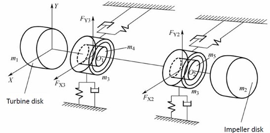
The rotor system actually is a continuous distribution of the elastic system, with an infinite number of degrees of freedom. In order to investigate the vibration characteristics of rotor system, it is necessary for us to establish the FEM model of the rotor system.
3.1. 3D model of turbine and impeller
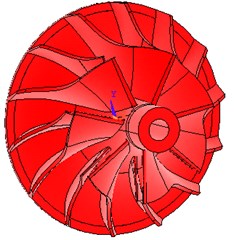
Due to the contour’s complexity of the impeller and turbine blade, so the 3D coordinate measuring instrument was used, and then the 3D CAD software such as UG, CATIA, Pro/E software were employed to establish the physical model of the turbine blade and impeller vane, and combined with measured three-dimensional coordinate of the wheel hub and rim lines simultaneously. After data processing, the three-dimensional model of turbine and impeller was built by UG software, shown as Fig. 6. Then the model was imported into ANSYS through the interface of the finite element software and the CAD software, shown as Fig. 7.
3.2. Floating-ring bearings model
The floating-ring bearings of rotor system have the functions of supporting rotor, reducing vibration and cooling off itself. The oil-layer stiffness and damping change with time, and they have some influences on the critical rotational speed of the rotor and on the oil film characteristic. In the process of modeling, the oil film stiffness only in vertical and horizontal direction was considered, and the inner oil film stiffness and the outer oil film stiffness were simplified as one spring. In FEM model, four spring-damping Combine14 elements were employed. The oil film stiffness of the floating-ring bearing model is shown as Fig. 8.
Fig. 63D model of turbine and impeller with UG

a)
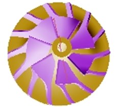
b)
Fig. 73D model of turbine and impeller with ANSYS
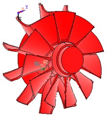
a)
b)
3.3. The rotor system model
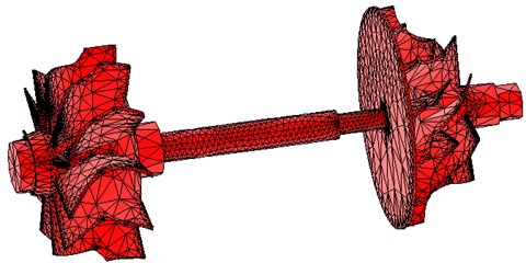
During the process of establishing the rotor system model, the rotor system’s structure was simplified to reduce the meshing difficulties and computing time. The impeller is made of aluminum alloy material, and its density is 2,680 kg/m3. Poisson’s ratio of this alloy changes little with temperature, so the approximate takes 0.3 and the elastic modulus is 69,800 N/mm2. The turbine needs to endure high temperature, so its structure is made of alloy steel. Its density is 7,730 kg/m3. Poisson’s ratio of this alloy steel takes 0.25 and the elastic modulus is 188,000 N/mm2. The rotor system was meshed in free-way. The SOLID185 with 8 nodes was used and the total elements were 135,498. The FEM model of the rotor system is shown as Fig. 9.
Fig. 8Floating-ring bearing model
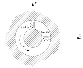
Fig. 9FEM model of the rotor system
4. Simulation on natural modes of the rotor system
Shown as Table 1, the rotor’s working rotational speed and oil film stiffness of floating-ring bearings were both considered in vibration simulation. The following commonly rotational speeds of 70,000 rpm, 80,000 rpm, 90,000 rpm, 950,000 rpm, 100,000 rpm, 105,000 rpm and 110,000 rpm were chosen. Then the inner oil-layer stiffness and outer oil-layer stiffness of floating-ring bearings were calculated with Eq. (12) to Eq. (15). The first 10 modal frequencies of the rotor system are shown in Table 1. The following Table 2 and Table 3 are the comparison of the first seven order modal frequencies of the rotor system under different speed conditions. The second mode to tenth mode are shown from Fig. 10 to Fig. 18.
According to above simulation results, we can find that the lower modes of rotor system are purely bent vibration and purely torsion vibration. When the modal order increases, its natural modes become gradually complicated and the higher modes are coupled bending and torsion mode.
Table 1The modal frequencies of the rotor system at different rotational speed and oil film stiffness
Speed / (104∙r∙min-1) | 0 | 7 | 8 | 9 | 9.5 | 10 | 10.5 | 11 |
Oil film stiffness in direction / (N∙mm-1) | 0 | 15.78 | 18.00 | 20.25 | 21.38 | 22.50 | 23.63 | 24.75 |
Oil film stiffness in direction / (N∙mm-1) | 0 | 11.32 | 13.74 | 14.55 | 15.36 | 16.16 | 16.97 | 17.78 |
1st mode / Hz | 95.1 | 565.3 | 595.4 | 627.0 | 643.3 | 659.8 | 676.6 | 693.5 |
2nd mode / Hz | 259.4 | 702.1 | 743.8 | 786.7 | 808.4 | 830.1 | 851.7 | 873.2 |
3rd mode / Hz | 423.2 | 956.5 | 1017.7 | 1068.1 | 1091.2 | 1113.5 | 1135.1 | 1156.4 |
4th mode / Hz | 780.1 | 1225.6 | 1317.3 | 1384.7 | 1414.8 | 1444.2 | 1473.6 | 1503.1 |
5th mode / Hz | 863.9 | 1328.4 | 1428.5 | 1562.5 | 1635.7 | 1771.1 | 1787.9 | 1865.6 |
6th mode / Hz | 1045.9 | 1482.5 | 1600.2 | 1731.0 | 1799.6 | 1869.7 | 1941.2 | 2013.8 |
7th mode / Hz | 1723.5 | 2933.5 | 2957.5 | 1731.0 | 2999.6 | 3015.4 | 3032.0 | 3049.5 |
8th mode / Hz | 2029.8 | 5133.5 | 5129.2 | 5123.5 | 5120.1 | 5116.5 | 5112.5 | 5108.2 |
9th mode / Hz | 3405.4 | 5460.6 | 5473.5 | 5487.7 | 5495.4 | 5503.3 | 5511.7 | 5520.3 |
10th mode / Hz | 4308.0 | 5833.5 | 5848.1 | 5864.2 | 5872.7 | 5881.8 | 5891.3 | 5901.2 |
Table 2Comparison of first seven order modal frequencies of the rotor system between 80,000 rpm and 90,000 rpm
Mode | 1 | 2 | 3 | 4 | 5 | 6 | 7 |
Natural frequency at 80,000 r∙min-1/ Hz | 595.4 | 743.8 | 1017.7 | 1317.3 | 1428.5 | 1600.2 | 2957.5 |
Natural frequency at 90,000 r∙min-1/ Hz | 627.0 | 786.7 | 1068.1 | 1384.7 | 1562.5 | 1731.0 | 2984.8 |
Relative growth rate / % | 5.3 | 5.8 | 4.9 | 5.1 | 9.4 | 8.2 | –1.0 |
Table 3Comparison of first seven order modal frequencies of the rotor system between 90,000 rpm and 100,000 rpm
Mode | 1 | 2 | 3 | 4 | 5 | 6 | 7 |
Natural frequency at 90,000 r∙min-1/ Hz | 627.0 | 786.7 | 1068.1 | 1384.7 | 1562.5 | 1731.0 | 2984.8 |
Natural frequency at 10,0000 r∙min-1/ Hz | 659.8 | 830.1 | 1113.5 | 1444.2 | 1771.1 | 1869.7 | 3015.4 |
Relative growth rate / % | 5.2 | 5.5 | 4.3 | 4.3 | 13.4 | 8.0 | –1.0 |
Fig. 10Second mode
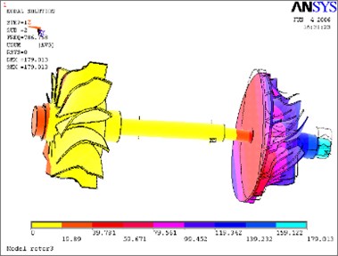
Fig. 11Third mode
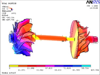
Fig. 12Fourth mode
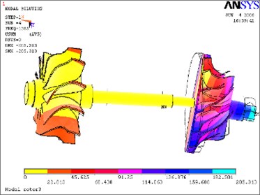
Fig. 13Fifth mode
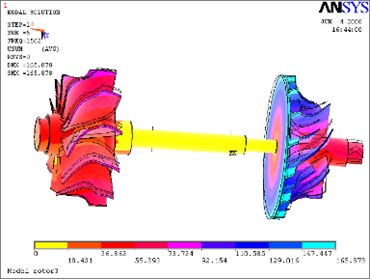
Fig. 14Sixth mode
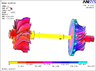
Fig. 15Seventh mode
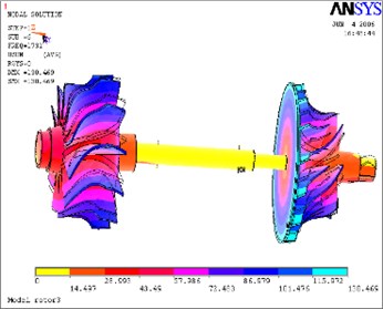
Fig. 16Eighth mode
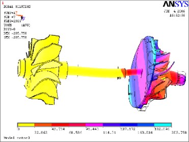
Fig. 17Ninth mode
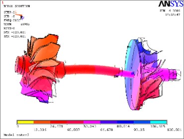
Fig. 18Tenth mode
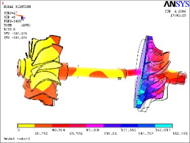
5. Modal testing analysis
This experiment was designed to use modal testing technology to identify the modal parameters of the rotor system. In the experiment, the information of rotor system was synchronously sampled while a pulse force excites rotor system, and then, the vibration response signals were obtained. The Data Acquisition and Signal Processing System were used, which are developed by China Orient Institute of Noise and Vibration.
5.1. Measurements points of bench test
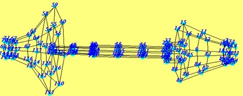
Fig. 19 is the photo of turbocharger’s rotor system. According to the characteristic of rotor structure and allowance position, we make layout of measurement points on the rotor system, shown as Fig. 20. Totally, 72 measurement points are used.
Fig. 19Photo of rotor system

Fig. 20The measurement of test point of rotor system
5.2. Experimental setup
The experiment was carried with a method of single-channel signal input, multi-channel signal output and schematic diagram of test is shown in Fig. 21. As shown in Fig. 22, the experimental setup includes choosing experimental parameters, setting up measurement points on turbocharger’s rotor system, choosing acquisition parameters, and so on.
Fig. 21Schematic diagram of test
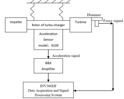
Fig. 22Test procedure chart
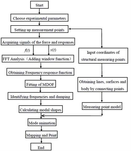
Fig. 23Entire transfer function curve of rotor system
5.3. Transfer function analysis
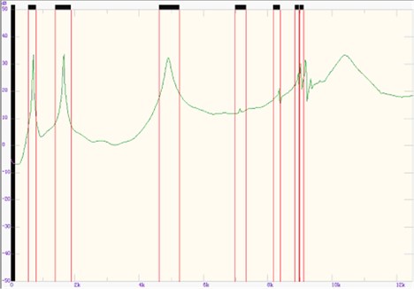
In order to know more modal information of rotor system, we get 72 transfer functions in this experiment. Then add every transfer function curves together and average them to a new total transfer function curve. The entire transfer function curve of rotor system is shown in Fig. 23.
As the natural frequencies of rotor system are below 12,500 Hz, so the sampling rate was set as 25,000 Hz. 72 acceleration signals and one force signal were synchronously. The data acquisition system was DASP 306. The vibration acceleration sensor model is BZ1102, its frequency response range of 2 Hz-15 kHz, and its sensitivity of 1 PC/ms-2.
5.4. Experiment results
The seven order natural frequencies and vibration modes of the rotor system were identified and are shown in Table 4. The first 2 natural modes are shown in Fig. 24 and Fig. 25. According to experimental results, the first 3 modes were verified and the relative error between simulation and modal test is about 10.2 %.
Fig. 24First mode
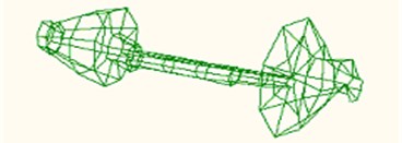
Fig. 25Second mode
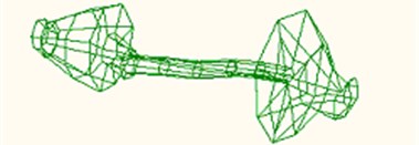
Table 4Seven order natural frequencies and natural modes of the rotor system
Mode | 1 | 2 | 3 | 4 | 5 | 6 | 7 |
Natural frequency with experiment / Hz | 700.8 | 1650.8 | 4900.4 | 7150.7 | 8355.5 | 8953.8 | 9013.3 |
Natural frequency with simulation / Hz | 780.1 | 1723.5 | 4308.0 | – | – | – | – |
Mode feature | Impeller and rotor shaft bending | Impeller, turbine and rotor shaft bending. Large bending at impeller. | Rotor shaft bending | Impeller and rotor shaft bending | Rotor shaft bending and torsing | Rotor shaft and impeller’s bending | Rotor shaft bending |
1) As Turbocharger’s working speeds are between 60,000 r/min and 250,000 r/min, the second mode with 1650.8 Hz will be easily stimulated. So not only does the resonant vibration of the rotor occur, but also do the oil whip and oil whirl of the floating-ring bearings appear at the speed of 99,048 r/min.
2) As the faults such as crack and wear will affect the stiffness of the rotor system, monitoring the natural modes of rotor system can help us to know turbocharger’s stability and reliability well and even forecast the life of the rotor system.
6. Conclusions
The natural modes of a turbocharger’s rotor system were simulated with FEM in this paper. The conclusions are obtained as following:
1) With the increase of the rotational speed of the rotor, floating-ring bearing stiffness produced by oil film force is continuously increased, so it strengthens the supporting stiffness of the entire rotor and increases the rotor natural frequency.
2) The lower modes of rotor system are purely bent vibration and purely torsion vibration. When the modal order increases, its vibration modes become gradually complicated and the higher modes are coupled bending and torsion mode. According to experimental results, the first 3 modes are verified and the maximum relative error between simulation and modal test is about 10.2 %.
3) According to simulation results with FEM method, it can conclude that the rotor model has resonance vibration under the working speed, so it is easy to make the turbocharger destroyed by the rotor vibration.
4) The effect of the across stiffness on the rotor’s floating-ring bearing are not considered in this simulation, and the data of the bearing stiffness is just obtained by the numerical calculation, which has not been verified. In addition, the boundary condition of the rotor is different in the actual instance, for example, the turbine is acted by the exhausted gas from engine and impeller is also acted by the turbocharged air. So the turbocharger’s rotor actual boundary condition should be considered for the further vibration mode analysis.
References
-
Li H. B., Zhou L. L., Shangguan Y. F. Analysis on the vibration modes of the rotor system of the turbocharger. Proceedings of BIT-TU Berlin Symposium on Turbocharging Technology, 2006, p. 121-128.
-
Koutsovasilis P., Driot N, Lu D. X. Quantification of sub-synchronous vibration for turbocharger rotors with full-floating ring bearings. Achieve of Applied Mechanics, Vol. 85, Issue 4, 2015, p. 481-502.
-
Li H. B., Zhou J. W., Sun Z. L. Mechanisms and Controls on Noise and Vibration of Automotive Turbocharger. China Machine Press, Beijing, 2012.
-
Li M., Li C., Liu X. B. Nonlinear rotor dynamics on turbo expander with unbalanced bearing force caused by temperature difference. Journal of Vibroengineering, Vol. 17, Issue 1, 2015, p. 33-46.
-
Brouwer M. D., Sadeghi F., Ashtekar A. Combined Explicit finite and discrete element methods for rotor bearing dynamic modelling. Trobology Transactions, Vol. 58, Issue 2, 2014, p. 300-315.
-
Ma H., Li H., Niu H. Q. Numerical and experimental analysis of the first and second mode instability in a rotor-bearing system. Achieve of Applied Mechanics, Vol. 84, Issue 4, 2014, p. 519-541.
-
Yue Y. M., Zhang H. T. Dynamic analysis for the rotor of turbocharger. Aviation Manufacture Technology, Vol. 4, 2004, p. 92-93.
-
Zhong Y. E., He Y. Z., Wang Z. Dynamic Analysis for the Rotor. Tsinghua University Press, Beijing, 2002.
-
Ying J., Jiao Y. H., Chen Z. B. Nonlinear Transient response of tilting 4 pad bearings-turbocharger systems. Proceedings of the ASME International Mechanical Engineering Congress and Exposition, Vol. 4B, 2014.
-
Huang R., Zhang W. L., Jiang Y. L. Influences of accelerating on dynamic characteristics of a turbochargers’ ball bearing-rotor system. Journal of Vibration and Shock, Vol. 33, Issue 11, 2014, p. 136-141.
-
Li G. J. Research of Dynamics Characteristics and Visualization on Rotor System of Turbocharger. Master Thesis, Hebei University of Technology, Tianjin, China, 2013.
-
Li H. L. The critical speed analysis of engine turbocharger based on matrix transfer matrix. Journal of Hefei University, Vol. 23, Issue 3, 2013.
-
Ashtekar A., Sadeghi F., Powers G. Experimental investigation of turbocharger rotor bearing system. Proceedings of the ASME Turbo Expo, Vol. 6, 2011, p. 559-566.
-
Zhu L., Wei D. G., Shi W. Effects of eccentricity on rotor dynamics characteristic of turbocharger. Chinese Journal of Automotive Engineering, Vol. 3, Issue 4, 2013, p. 282-286.
