Abstract
This paper is concerned with the free vibration of cantilever microbeams with attached tip mass in a systematical manner. Small size effects on the vibrations of the microbeam are taken into consideration by introducing a scale parameter. A Fourier sine series is used to represent the lateral displacement function. Stokes’ transformation is applied in the present formulation and corresponding derivatives are presented explicitly. The present formulations can be readily reduced to those for others classical elasticity models by setting corresponding small scale parameter to zero. Several parametric studies are performed to validate the present solutions and the effects of various important physical parameters (scale parameter, tip mass) are investigated.
1. Introduction
Microbeams (MEMS) and nanobeams (NEMS) such as doubly clamped and cantilever microbeam are the major components of MEMS and NEMS devices, and the preferred actuation method is always the electric actuation. The analysis of this actuation and sensing has been a topic of interest over the past several years. Different sensing and actuation properties such as electrostatic, thermal, piezoelectric, piezosensitive, optical and electromagnetic have been used [1].
Microbeams, as the most widely used microscale continuous elements, can be found in various microelectromechanical devices [2]. Nowadays, the usage of beam-shaped structures has widely spread in micro and nano electromechanical systems (MEMS and NEMS) as elements such shock sensors [3], micro-actuators [4], accelerometers [5], bio-MEMS [6], atomic force microscopes, and so on [7, 8]. The critical physical dimensions of MEMS devices can vary from well below one micron on the lower end of the dimensional spectrum, all the way to several millimeters. While the functional elements of MEMS are miniaturized structures, sensors, actuators, and microelectronics, the most notable (and perhaps most interesting) elements are the microsensors and microactuators [9]. However, beam model based on the classical theory (CT), such as Euler-Bernoulli [10-12], Timoshenko [11, 12] and some higher-order shear deformation [12, 13] beam theories is not capable of capturing size effect in micro/nano-structures as a result of lacking of the material length scale parameter [14]. In order to capture the size effect in microstructures, some non-classical continuum theories such as the non-local, strain gradient, and couple stress have been introduced and developed [15]. Strain gradient elasticity models of continuum mechanics are recognized within the wide literature as material models capable to capture and describe a number of experimentally detected microstructural phenomena featured by an internal length scale, such as size effects, surface effects, dispersion effects of wave propagation, along with the possibility to dispense with stress/strain singularities at, typically, crack tips and dislocation cores [16, 17].
Micro scale mass sensors offer the potential of meeting the high-performance requirement of many mass sensing applications. These sensors employ the characteristic of micro resonators in frequency shifting due to mass loading. The micro-scale mass sensing with a micro resonator is based on the fact that the resonant frequency is sensitive to the attached tip mass. In order to determine the effects of attached mass on the resonant frequency of micro/nanoscale application, the continuum models based on microbeam as well as nanaobeam is used by several researchers [18-20].
The method of Stokes’ transformation is more efficient than the analytical series methods because this method gives more flexibility in boundary conditions. This is in particular essential for determining the dynamic response of microbeams other than simply supported. In this paper, we aim to develop a coefficient matrix for free vibrations of cantilever microbeams with small scale effects. Starting from the non-classical boundary conditions, we sequentially employ the Stokes’ transformation technique and the Fourier sine series, to derive systems of linear equations, where Fourier coefficients involved are determined by the governing equation. The present analytical solutions can be readily reduced to those for the classic beam without mass effect, simply by setting small scale parameter to zero.
2. Theoretical analysis
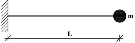
MEMS sensors for chemical analysis have been based on detection techniques. They are required for many industries. The most commonly used material for fabricating MEMS is silicon compounds. The frequency shift can be defined as the difference between the natural frequencies of a micro cantilever with and without tip mass, that serves as an index to estimate quantitatively the dynamical behavior of the micro-mass sensor in gradient elasticity. In this study, uniform micro-mass sensor could be simplified as a cantilever beam of length and carrying a concentrated tip mass m at the free end, as shown in Fig. 1. For a uniform cantilever microbeam with attached tip mass (Fig. l), the equation of motion with shear and rotatory effects ignored is [21]:
where is the lateral displacement at distance along the length of the beam and time , the flexural rigidity of the beam, the mass density and the cross-sectional area of the beam. denotes the simply gradient elastic modulus. Eq. (1) is well known as strain gradient Euler-Bernoulli equation for a uniform cross section microbeam, for which, the solution exists in the form:
Fig. 1A cantilever microbeam with attached tip mass
Because of the unusual nature of boundary condition involved (see Fig. 1), the lateral displacement function can be rewritten in the form:
where is the modal displacement function and is the natural frequency. According to the boundary conditions one may assume that:
The partial differential equation given in Eq. (1) is called a two-point boundary value problem. Fourier sine series given in Eq. (4) satisfies only the natural boundary conditions of a microbeam whose boundaries are simply supported, so we should use a more sophisticated mathematical procedure known as Stokes’ transformation and try to develop a general code in order to calculate vibrational response. The higher order derivatives of based on the Stokes’ transformation become [22]:
where:
Detailed information on Stokes’ transformation is presented in [22, 23]. Eqs. (8) and (10) are substituted into Eq. (1) to result in:
Therefore, the Fourier coefficient can be written in terms of , , ,, and as follows:
where:
Hence, the lateral displacement function for the microbeam having no geometrical constraints at both ends becomes:
The inclusion of the scale parameter () in the Eq. (15) takes into account the effects of scale-factor.
3. Boundary conditions
Consider a clamped free microbeam with point mass at the free end, as shown in Fig. 1. The strain gradient boundary conditions are mathematically written as:
The resulting systems of linear equations are found from Eqs. (13), (16) and (17):
where:
The equation system given in Eqs. (l8) and (l9) can be expressed in the following matrix form:
where:
The vibration frequencies of cantilever micro-sized beam with attached tip mass can be achieved by solving the following eigenvalue problem:
The micro-mass sensing is based on the fact that the resonant frequency is sensitive to the attached tip mass. The attached tip mass causes a shift to the resonant frequency. The frequency shift can be defined as the difference between the frequencies of the microbeam with and without the attached tip mass, which serves as an index to judge quantitatively the dynamical behavior of the micro-mass sensor. The main advantage of above determinant is that it is not necessary to solve the problem for each change in boundary condition. Only Eq. (28) is required, which can be used any type of boundary condition specified in Eqs. (16)-(17).
4. Numerical results
In this section, different numerical examples are conducted to assess the utility and applicability of proposed approach for calculating the vibration frequencies of a microbeam. Before we proceed further, we first assess the accuracy of the present analytical method by comparing the natural frequency parameters for a classical cantilever Euler Bernoulli beam obtained from the present approach to that obtained from the literature. It is seen from Table 1 that the numerical results, which are degenerated from the present analytical solutions, are very close to those obtained by Kim and Kim [24]. In this work, 50 terms of infinite series are used to calculate vibration frequencies. From an engineering point of view, the accuracy of present solutions can be considered sufficient.
Fig. 2 shows the first three dimensionless frequencies as a function of mass parameter, for selected small scale parameter (1). It is seen that the mass parameter has a significant effect on the dimensionless natural frequencies especially for lower modes having lower frequencies. As the mass parameter increases, the dimensionless natural frequencies gradually decrease.
The first three dimensionless frequency ratios of a cantilever microbeam with different values of the small scale parameter (0, 0.01, 0.02, 0.03, 0.04,… , 0.09) are displayed in Fig. 3 for the case of amass ( 1). Index (GE) denotes the gradient elasticity theory and (CE) denotes the classical elasticity theory. The most important observation from the Fig. 3 is that vibrational response of a microbeam with an attached mass are strongly affected by the scale parameter.
Table 1Comparisons of the first three dimensionless angular frequencies
Mode-1 | Mode-2 | Mode-3 | ||||
M | Ref [24] | Present (×) | Ref [24] | Present (×) | Ref [24] | Present (×) |
0.01 | 1.8583 | 1.8715 | 4.6532 | 4.6830 | 7.7880 | 7.8424 |
0.1 | 1.7339 | 1.7343 | 4.4019 | 4.4243 | 7.4544 | 7.4895 |
1 | 1.2484 | 1.2530 | 4.0327 | 4.0476 | 7.1367 | 7.1637 |
10 | 0.7360 | 0.7381 | 3.9400 | 3.9545 | 7.0781 | 7.1049 |
100 | 0.4161 | 0.4172 | 3.9293 | 3.9439 | 7.0718 | 7.0986 |
Fig. 2The first three dimensionless frequencies as a function of attached mass
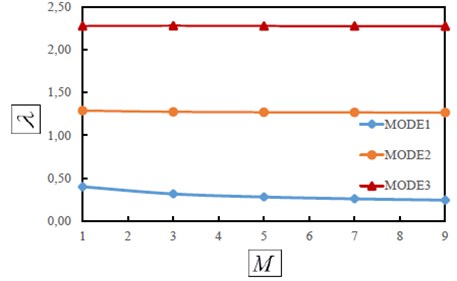
Fig. 3The first three dimensionless frequency ratios λiGE/λiCE as a function of small scale parameter
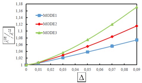
Fig. 4Graph of the first three dimensionless frequency ratios λiGE/λiCE against number of terms in expansion
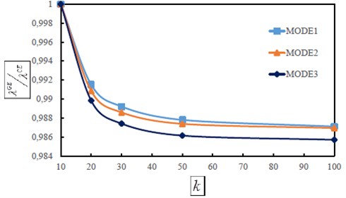
In Fig. 4 the variation of the first three dimensionless frequency ratios with the number of terms used in the Fourier series is depicted. It is seen that 70-80 terms of infinite Fourier sine series can be satisfactory to obtain the vibrational response with accuracy lower than 2,5 percent.
5. Conclusions
The dynamic response of cantilever Euler-Bernoulli microbeams in the presence of tip mass is given, employing the Fourier sine series and Stokes’ transformation. A coefficient matrix for microbeams with different boundary conditions are explicitly derived in terms of infinite series. The different comparisons are made to ensure the accuracy of the results. An excellent agreement is observed, hence validating the present solutions. Numerical calculations are performed to examine the effect of different parameters. Results clearly reveal that small scale parameter plays an important role in determining the vibration frequencies.
References
-
Batra R. C., Porfiri M., Spinello D. Vibrations of narrow microbeams predeformed by an electric field. Journal of Sound and Vibration, Vol. 309, Issues 3-5, 2008, p. 600-612.
-
Ghayesh M. H., Farokhi H., Alici G. Subcritical parametric dynamics of microbeams. International Journal of Engineering Science, Vol. 95, 2015, p. 36-48.
-
Currano L. J., Yu M., Balachandran B. Latching in a MEMS shock sensor: modeling and experiments. Sensors and Actuators A: Physical, Vol. 159, 2010, p. 41-50.
-
Li L., Chew Z. J. Smart Sensors and MEMS, 1st Edition, Intelligent Devices and Microsystems for Industrial Applications. Microactuators: Design and Technology, Woodhead Publishing, 2013, p. 305-348.
-
Davies E., George D. S., Gower M. C., Holmes A. S. MEMS FabryProt optical accelerometer employing mechanical amplification via a V-beam structure. Physica E, Vol. 215, 2014, p. 22-29.
-
Djuric Z., Jokic I., Peles A. Fluctuations of the number of adsorbed molecules due to adsorption desorption processes coupled with mass transfer and surface diffusion in bio/chemical MEMS sensors. Microelectronic Engineering, Vol. 124, 2014, p. 81-85.
-
Kahrobaiyan M. H., Rahaeifard M., Ahmadian M. T. Nonlinear dynamic analysis of a V-shaped microcantilever of an atomic force microscope. Applied Mathematical Modelling, Vol. 35, Issue 12, 2011, p. 5903-5919.
-
Karparvarfard S. M. H., Asghari M., Vatankhah R. A geometrically nonlinear beam model based on the second strain gradient theory. International Journal of Engineering Science, Vol. 91, 2015, p. 63-75.
-
Şimsek M. Nonlinear static and free vibration analysis of microbeams based on the nonlinear elastic foundation using modified couple stress theory and He’s variational method. Composite Structures, Vol. 112, 2014, p. 264-272.
-
Khalili S. M. R., Jafari A. A., Eftekhari S. A. A mixed Ritz-DQ method for forced vibration of functionally graded beams carrying moving loads. Composite Structures, Vol. 92, Issue 10, 2010, p. 2497-2511.
-
Li S. R., Batra R. C. Relations between buckling loads of functionally graded Timoshenko and homogeneous Euler-Bernoulli beams. Composites and Structures, Vol. 95, 2013, p. 5-9.
-
Simsek M. Vibration analysis of a functionally graded beam under a moving mass by using different beam theories. Composite Structures, Vol. 92, Issue 4, 2010, p. 904-917.
-
Giunta G., Crisafulli D., Belouettar S., Carrera E. Hierarchical theories for the free vibration analysis of functionally graded beams. Composite Structures, Vol. 94, Issue 1, 2011, p. 68-74.
-
Xie X., Zheng H., Yang H. Indirect radial basis function approach for bending, free vibration and buckling analyses of functionally graded microbeams. Composite Structures, Vol. 131, 2015, p. 606-615.
-
Taati E., Najafabadi M. M., Tabrizi H. B. Size-dependent generalized thermoelasticity model for Timoshenko microbeams. Acta Mechanica, Vol. 225, Issue 7, 2014, p. 1823-1842.
-
Polizzotto C. A unifying variational framework for stress gradient and strain gradient elasticity theories. European Journal of Mechanics A/Solids, Vol. 49, 2015, p. 430-440.
-
Yaylı M. Ö., Çerçevik A. E. Axial vibration analysis of cracked nanorods with arbitrary boundary conditions. Journal of Vibroengineering, Vol. 17, Issue 6, 2015, p. 2907-2901.
-
Chowdhury R., Adhikari S., Mitchell J. Vibrating carbon nanotube based bio-sensors. Physica E: Low-dimensional Systems and Nanostructures, Vol. 42, Issue 2, 2009, p. 104-109.
-
Joshi A. Y., Harsha S. P., Sharma S. C. Vibration signature analysis of single walled carbon nanotube based nanomechanical sensors. Physica E: Low-dimensional Systems and Nanostructures, Vol. 42, Issue 8, 2010, p. 2115-2123.
-
Mehdipour I., Barari A., Domairry G. Application of a cantilevered SWCNT with mass at the tip as a nanomechanical sensor. Computational Materials Science, Vol. 50, Issue 6, 2011, p. 1830-1833.
-
Papargyri-Beskou S., Tsepoura K. G., Polyzos D., Beskos D. E. Bending and stability analysis of gradient elastic beams. International Journal of Solids and Structures, Vol. 40, 2003, p. 385-400.
-
Yayli M. O. Stability analysis of gradient elastic microbeams with arbitrary boundary conditions. Journal of Mechanical Science and Technology, Vol. 29, Issue 8, 2015, p. 3373-3380.
-
Yayli M. O. Buckling analysis of a rotationally restrained single walled carbon nanotube. Acta Physica Polonica A, Vol. 127, 2015, p. 678-683.
-
Kim H. K., Kim M. S. Vibration of beams with generally restrained boundary conditions using Fourier series. Journal of Sound Vibration, Vol. 245, Issue 5, 2001, p. 771-784.
Cited by
About this article

