Abstract
Pile foundations are typically comprised in concealed construction work. In recent years, some major categories of concrete piles subject to typical damages have caused a lot of engineering disasters and accidents. These accidents have been caused by collapse of civil structures resulting in great casualties and economic loss. Therefore, damage detection and real-time health monitoring on foundation piles is an urgent research requirement. In this research, a piezoceramic based passive sensing approach is proposed to detect typical damages types of concrete piles, including partial mud intrusion, secondary concrete pouring interface, circumferential crack, and full mud intrusion. In this passive sensing approach, induced stress waves are generated by the impact hammer on the top surface of a pile and one smart aggregate embedded on the bottom of each pile is used as a sensor to receive the propagating wave signals. These sensors are embedded before pouring concrete. Structural defects affect the natural frequency of the pile. The power spectrum of piles with different types of damage were compared by plotting the sensor signals in frequency domain. The natural frequency decreases with the increase in defect severity. The experimental results demonstrate that the proposed approach can detect all four typical damage types in concrete piles.
1. Introduction
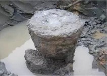
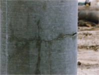
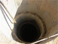
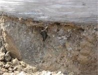
Pile foundation is a concealed civil construction. In recent years, a lot of engineering accidents have occurred due to damages in pile foundation. The reasons are multifarious, such as construction quality, disturbances caused by nearby construction, shear failure due to horizontal force. Four typical damage types of concrete piles are shown in Fig. 1. These damages have caused structure failures that have resulted in collapse or incline in buildings, resulting in casualties and economic loss.
Foundation piles, which were designed and constructed to transfer the structural load to the foundation, play a very important role for the safety and normal operation of structures worldwide. A lot of research has been done to develop efficient and effective techniques to monitor the health condition of pile structures. Among them, three major techniques; low strain integrity tensing [1-3]; Rauschelet [4] applied high strain dynamic to test integrity of piles and Cross-hole sonic logging [5, 6] have been widely applied and developed into the current commercial health monitoring technology. Furthermore, some new techniques, such as fiber based and vibration based approaches have also been proposed in recent decades to evaluate the damage status of the concrete piles. Nishimura [7] employed bending tests and electrical resistance measurements to investigate the function and performance of the self-diagnosis composites embedded in concrete piles. Baldwin [8] utilized optical fiber Bragg grating sensors embedded in the filament wound composite tube of a loading carrying pile to monitor the health condition for the lifetime of the pile. Glisic [9] utilized fiber optic sensors to assess the pile foundation performance during axial compression, pullout and flexure test. Matsumoto [10] carried out a one-dimensional stress wave analysis of the statnamic test to estimate the static load settlement behavior of the test pile and the profile of the soil properties.
Fig. 1The typical damage types in concrete piles: a) fractured pile, b) cracked pile, c) pile with secondary concrete pouring, d) pile with mud intrusion
a)
b)
c)
d)
Due to their special property of dual capacity to be used as a sensor and an actuator, piezoceramic transducers have been researched in damage detection and structural health monitoring of concrete structures [11-13]. The piezoelectric material based health monitoring method has provided a promising approach for health monitoring of large scale concrete structures. Ayres [14] utilized a piezoelectric actuator/sensor to measure the electrical impedance and then detect the presence of damage and monitor its progression in concrete structures. Although piezoceramic based technique has been applied to various kinds of structures, there are very few scientific papers related to concrete pile health monitoring using piezoceramic. Saafi [15] utilized an array of piezoelectric transducers to detect the disbonds and delamination of advanced composite reinforcement from concrete structures. Quek [16] used the experimental dynamic response data obtained from piezoelectric sensors to locate the crack position in the beam. Song [17] employed an active sensing network formed by embedding the smart aggregates in the concrete piles before casting for the health monitoring purpose. Wang [18] also designed two bored piles instrumented with embedded piezoceramic transducers to detect the crack or damage condition. The experimental result shows that the amplitude of the wave and the transmission energy decreases due to the existence of cracks or damage. However, only active sensing approach was utilized in these papers, and only one damage condition (crack) was considered in these researches.
Some research has also been conducted regarding impact testing with piezoelectric transducers. Lorenz [19] have designed and calibrated an impact penetrometer using a piezoelectric transducer for use on a spacecraft to land on the surface of Titan, one of Saturn’s moons. Lee [20] have designed and built an ultra-high precision and high speed piezoelectric impact system. The experimental data indicates that this piezoelectric impact hammer has a timing accuracy in the range of microseconds and a positioning accuracy in the range of micrometers. Tong [21] have designed and fabricated a piezoelectric impact hammer for nondestructive evaluation of concrete structures.
In order to test the feasibility of passive sensing approach with piezoceramic transducers to monitor the health of pile concrete structures, use of embedded smart aggregates is proposed in this paper. Five concrete pile specimens, including one healthy and four damaged representing crack, partial mud intrusion, secondary pouring, and full mud intrusion, were designed, fabricated and tested in this research. Each specimen has one smart aggregate embedded at the bottom of pile before concrete pouring. The experimental results indicated that the proposed approach can detect all four typical damage types in concrete piles. In addition, this approach also provides an intelligent system which can provide real-time monitoring of foundation piles when they are impacted by external forces.
2. Smart aggregate transducers and passive sensing approach
2.1. Smart aggregate transducers
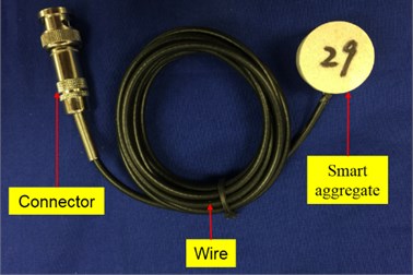
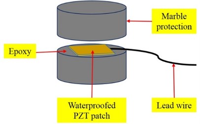
Piezoelectric materials exhibit direct and converse piezoelectric effect. When the piezoelectric material is subject to a stress or strain, it will generate electric charge, which is called the direct piezoelectric effect. The converse piezoelectric effect is the reversed process of applying electric field to produce stress or strain. The PZT (Lead Zirconate Titanate) is one of the most commonly used piezoelectric materials with a strong piezoelectric effect. Since the PZT material is fragile and has many limitations in field applications, a smart aggregate is designed by sandwiching the waterproofed PZT with protection materials (Fig. 2). The diameter and the height of the smart aggregate is 25 mm and 20 mm respectively. The dimension of the PZT patch is 15 mm×15 mm×0.2 mm [22]. With the integrated piezoceramic patch, a smart aggregate transducer embedded in concrete can function as an actuator to generate a stress wave or as a sensor to detect a stress wave.
Fig. 2Smart aggregate: a) a photo of a smart aggregate with a connector, b) schematic structure
a)
b)
2.2. Passive sensing approach
Based on the piezoelectric principle, the passive sensing approach can be simply illustrated by using one embedded smart aggregate as a sensor. The hammer is connected to a power supply. When the hammer impacts the top of the specimen, it generates an induced stress wave, which propagates along the pile structure. Simultaneously, one smart aggregate acts as a sensor to detect or measure the propagating stress wave. The strength of the received signal from the sensor is directly correlated to the conduit continuity of the stress wave propagation path. Therefore, this method can be developed to monitor the continuity of the stress wave propagation conduit, which in this case can be a concrete pile.
3. Principle of damage detection of concrete piles
3.1. Stress wave energy attenuation through damage interfaces
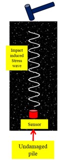
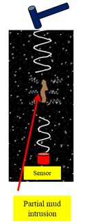
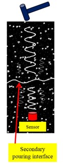
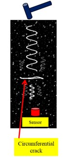
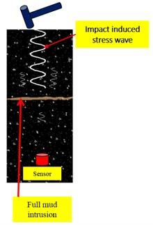
If a damage exists along the stress wave path, it changes the continuity of the stress wave propagation conduit. The received stress wave energy will be attenuated corresponding to different damage interfaces encountered. The schematics of stress wave propagation through different damage interfaces using embedded smart aggregates to receive signals in concrete piles are shown in Fig. 3. In Fig. 3(a), there is no damage along the stress wave path; In Fig. 3(b), the partial mud is encountered across the stress wave path; In Fig. 3(c), there is a secondary concrete pouring interface across the stress wave path; In Fig. 3(d), there is a crack across the stress wave path; and, In Fig. 3(e), the full mud intrusion behaves like a fractured interface across the stress wave path. It can be seen that when the exited stress waves are the same for each case, the smart aggregate sensor associated with the case of no damage receives the most energy among all sensors. Conversely, the sensor associated with the full mud intrusion reports minimum energy as mud layer can absorb most of the stress wave energy. The received energy in other damage interfaces, including partial mud intrusion, secondary concrete pouring, and the crack, depends on the actual condition of the damage interface, such as location, dimension, shape, and etc.
Fig. 3Schematics of stress wave propagation through different damage interfaces: a) no damage along the stress wave path, b) partial mud across the stress wave path, c) secondary concrete pouring interface across the stress wave path, d) crack across the stress wave path, e) full mud intrusion like a fractured interface cross the stress wave path
a)
b)
c)
d)
e)
3.2. Frequency response based damage detection of concrete piles
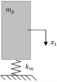
The concrete piles can be simplified to an undamped spring-mass vibration system. The natural frequency of concrete piles will change when the damage occurs, because the frequency response characteristics of concrete piles are decided by their mass, stiffness and boundary conditions. For an undamaged pile, it can be simplified to a single freedom mass-spring vibration system as shown in Fig. 4(a). The mass of pile is , the stiffness of mud is . With this vibration module, the natural frequency of undamaged pile can be computed as follows:
For other four categories of piles with damage i.e. partial mud intrusion, secondary pouring, crack, and full mud intrusion, the stiffness will be lower than normal stiffness attributed to the decrease in section area. A damaged pile can be simplified to a two degrees of freedom mass-spring vibration system as shown in Fig. 4(b). Since the total mass of pile will be unchanged due to damage, a parameter, (), is used to denote the ratio of mass of upper block to total mass of undamaged pile . Therefore, the mass of and should be and respectively. Their free vibration equations have the following form:
where:
is mass matrix:
is stiffness matrix:
Therefore, the first natural frequency is:
where and .
It can be proved that . This shows that the first natural frequency of damaged pile will be less than that of an undamaged pile. The natural frequency of damaged pile highly depends on the actual condition of the damage such as location, size, shape, etc. The location of the damage will influence the parameter i.e. the ratio of mass of upper block to total mass of undamaged pile and the size will influence the stiffness in damaged pile. Therefore, the order of the energy values corresponding to three cases may differ depending upon the actual condition. Higher stiffness values for will result in larger first natural frequency of damaged piles.
Fig. 4Vibration models of five categories of concrete piles
a) Single-freedom-mass-spring vibration module of undamaged pile
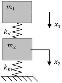
b) Two-degree-of-freedom mass-spring vibration module
4. Concrete pile specimens and experimental setup
This section describes the concrete pile specimens that will be used to demonstrate the smart aggregate based passive sensing approach for damage detection. In addition, the experimental setup that involves the data acquisition system is also described.
4.1. Concrete pile specimens
Fig. 5 shows the schematics of five concrete pile specimens. Please note that one has no damage and the other four have different artificially created damages, which involve the partial mud intrusion, the secondary pouring interface, the circumferential crack, and the full mud intrusion, respectively. To enable the passive sensing approach, one smart aggregate was embedded in each specimen at pre-determined locations. A total of five smart aggregates were used. The five smart aggregates were sequentially numbered SA1 to SA5, as shown in Fig. 5. Please note that along the path to SA1, there is no damage. However, partial mud exists along the path to SA2, a secondary concrete pouring interface exists along the path to SA3, a circumferential crack exists along the path to SA4, and a full mud intrusion that is like a fractured interface exists along the path to SA5. Fig. 6 depicts the impact hammer. In this experiment, it has been used to give an impact force on the top of each specimen.
Fig. 5Schematics of the concrete pile specimens
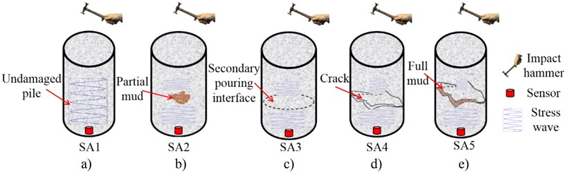
Fig. 6Impact hammer
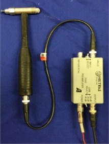
Fig. 7Specimens with one undamaged pile and four damaged piles with different damage interfaces
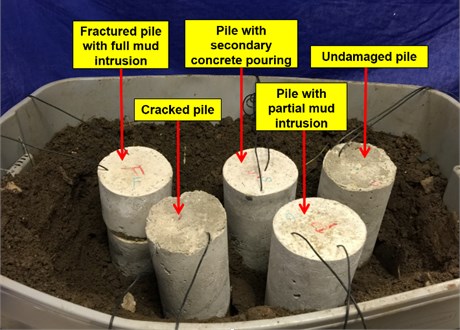
Fig. 8Experimental setup
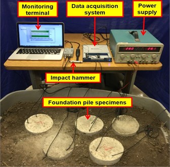
4.2. Experimental setup
Fig. 8 shows the experimental setup for the tests. The data acquisition system associated with a laptop is used to receive signal from sensors. The sampling rate of the data acquisition system is 1 MHz. The technical specifications of the data acquisition system are provided in Table 1.
Table 1The technical specifications of the data acquisition system
Low pass cutoff frequency | Sampling rate | Time interval | Power supply |
1 MHz | 1 MHz | 1 s | 28 V |
5. Experimental results
5.1. Experimental procedures
The experiments involved five separate tests of five pile specimens with different types of damages, as shown in Fig. 5. For each set of tests, five experiments were conducted. First set of tests with SA1 as a sensor to detect the wave response were used as a baseline as there is no damage on the path to SA1. SA2, SA3, SA4 and SA5 were used to detect the wave response through partial mud, secondary pouring interface, circumferential crack and full mud intrusion respectively. In all the tests, the excitation signals were made by the impact hammer. In this paper, the data measured from the damaged piles was compared to the baseline data from undamaged pile. Based on different damage types, different attenuation ratios in each case were obtained.
5.2. Damage detection
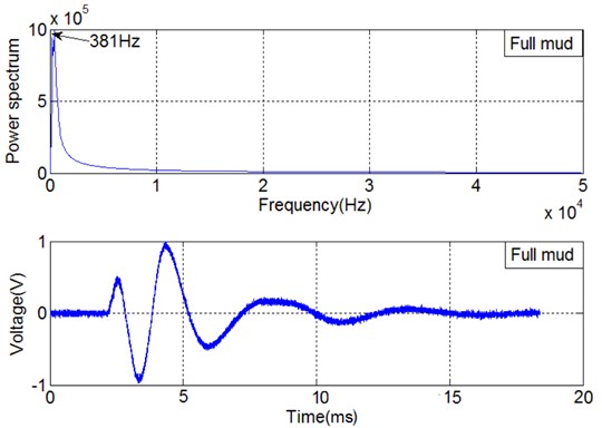
The signals from five experiments are shown in Figs. 9-13. It can be clearly observed that the power spectrum in case of an undamaged pile specimen, as shown in Fig. 9, is higher compared to four cases with different damage types, as shown in Figs. 10-13. In addition, the lowest power spectrum is obtained in case of full mud intrusion. Thus, it can be concluded that structural defect affects the resonance frequency of the pile. Also, the power spectrum of the sensor signal received from undamaged pile is the greatest among others and the resonance frequency decreases with the increase in defect severity. Lowest values are obtained in full mud intrusion as it behaves as a fractured interface in concrete.
Fig. 9Time domain signal of SA1 and power spectrum associated with undamaged pile specimen
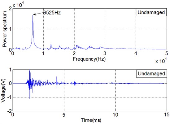
Fig. 10Time domain signal of SA2 and power spectrum associated with partial mud intrusion
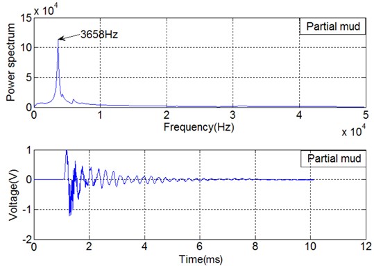
Fig. 11Time domain signal of SA3 and power spectrum associated with secondary pouring interface
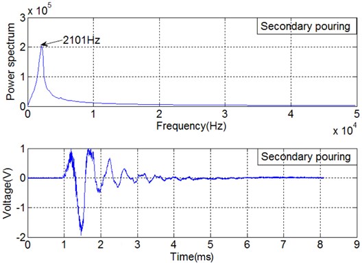
Fig. 12Time domain signal of SA4 and power spectrum associated with circumferential crack
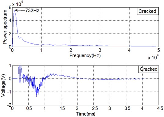
Fig. 13Time domain of SA5 and power spectrum associated with full mud intrusion
5.3. Power spectrum analysis
As analyzed in Section 3.2, the first natural frequency of damaged pile will be less than that of an undamaged pile . Also, the masses and are equivalent in these experiments. Therefore, the stiffness attributed to damage is the only contributing parameter to the natural frequency of damaged piles. The descending order of damage caused stiffness for four damaged pile is partial mud intrusion, secondary concrete pouring, cracked pile and full mud intrusion. Therefore, the descending order of natural frequency for five kinds of piles is undamaged pile, partial mud intrusion, secondary concrete pouring, cracked pile and full mud intrusion as shown in Fig. 14.
Fig. 14Resonance frequencies of the five piles
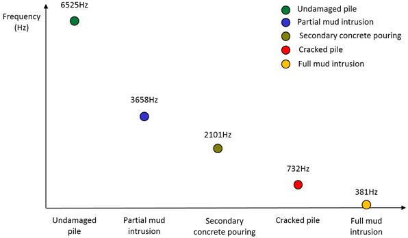
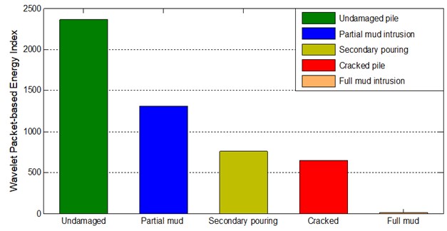
Fig. 15 shows the power spectrum indices of the sensor signal received from the five tests. It is clear that the frequency index associated with the case of undamaged pile reports the highest value. Further, the index values are in descending order for partial mud intrusion, secondary concrete pouring, circumferential crack, and full mud intrusion reporting the lowest value. It can be seen that the natural frequency decreases with the increase of defect severity which can be utilized to detect the different damage interfaces from concrete piles. Thus, the experimental results closely match the theoretical calculations.
5.4. Discussion – comparison to the energy based active sensing approach
Fig. 15 shows the energy indices associated with different damage interfaces from the five concrete pile specimens. It can be clearly visualized that the order from highest value to lowest value carries from undamaged pile to the one with full mud intrusion. Stress wave attenuation ratio also increases from an intact pile to full mud intrusion. Thus, the results of power spectrum analysis are in good agreement with the ones using wavelet packet based energy analysis.
Fig. 15Energy indices for five experiments
6. Conclusion
The proposed piezoceramic based passive sensing approach was experimentally demonstrated to be a feasible approach for damage detection and distinction of the concrete piles subject to typical damage. Structural defects affect the resonance frequency of the pile as resonance frequency decreases with the increase in defect severity. In the time domain analysis utilizing the power spectrum, the resonance frequency of the investigated piles was obtained in the descending order with undamaged pile, pile with partial mud intrusion, pile with secondary concrete pouring, cracked pile and fractured pile with full mud intrusion with the lowest value. The results show good agreement with the signal energy values using wavelet packet based energy analysis and energy indices. In the future application of health monitoring, embedded smart aggregates can be used to monitor in real-time the health status of foundation piles when they are impacted by external forces during both building construction and operations.
References
-
Morgano C. M. Low strain testing of piles utilizing two acceleration signals. Fifth International Conference on the Application of Stress-Wave Theory to Piles, Orlando, FL, 1996.
-
Massoudi N., Teffera W. Non-destructive testing of piles using the low strain integrity method. Fifth International Conference on Case Histories in Geotechnical Engineering, 2004.
-
White B., Nagy M., Allin R. Comparing cross-hole sonic logging and low-strain integrity testing results. Proceedings of the Eighth International Conference on the Application of Stress Wave Theory to Piles, 2008.
-
Rauschel F., Likinsz G. E., Husseiu M. Pile integrity by low and high strain impacts. 1988, p. 44-55.
-
Haramy K. Y., Mekic-Stall N. Cross-Hole Sonic Logging and Tomographic Imaging Survey to Evaluate the Integrity of Deep Foundations – Case Studies. Federal Highway Administration, Central Federal Lands Highway Division, 2000.
-
Camp W., Holley D., Canivan G. Crosshole sonic logging of South Carolina drilled shafts: a five-year summary. Deep Foundations, American Society of Civil Engineers, 2007, p. 1-11.
-
Nishimura H., Sugiyama T., Okuhara Y., Shin S.-G., Matsubara H., Yanagida H. Application of self-diagnosis FRP to concrete pile for health monitoring. SPIE’s 7th Annual International Symposium on Smart Structures and Materials, 2000.
-
Baldwin C. S., Salter T., Niemczuk J. B., Chen P. C., Kiddy J. S. Structural monitoring of composite marine piles using multiplexed fiber Bragg grating sensors: in-field applications. SPIE’s 9th Annual International Symposium on Smart Structures and Materials, 2002.
-
Glisic B., Inaudi D., Nan C. Pile monitoring with fiber optic sensors during axial compression, pullout, and flexure tests. Transportation Research Record: Journal of the Transportation Research Board, Vol. 1808, 2002, p. 11-20.
-
Matsumoto T., Kitiyodom P., Matsu H., Katsuzaki Y. Monitoring of load distribution of the piles of a bridge during and after construction. Soils and Foundations, Vol. 44, Issue 4, 2004, p. 109-117.
-
Gu H., Song G., Dhonde H., Mo Y., Yan S. Concrete early-age strength monitoring using embedded piezoelectric transducers. Smart Materials and Structures, Vol. 15, Issue 6, 2006, p. 1837.
-
Song G., Gu H., Mo Y.-L. Smart aggregates: multi-functional sensors for concrete structures – a tutorial and a review. Smart Materials and Structures, Vol. 17, Issue 3, 2008, p. 033001.
-
Feng Q., Kong Q., Huo L., Song G. Crack detection and leakage monitoring on reinforced concrete pipe. Smart Materials and Structures, Vol. 24, Issue 11, 2015, p. 115020.
-
Ayres J. W., Lalande F., Chaudhry Z., Rogers C. A. Qualitative impedance-based health monitoring of civil infrastructures. Smart Materials and Structures, Vol. 7, Issue 5, 1998, p. 599.
-
Saafi M., Sayyah T. Health monitoring of concrete structures strengthened with advanced composite materials using piezoelectric transducers. Composites Part B: Engineering, Vol. 32, Issue 4, 2001, p. 333-342.
-
Quek S., Wang Q., Zhang L., Ong K. Practical issues in the detection of damage in beams using wavelets. Smart Materials and Structures, Vol. 10, Issue 5, 2001, p. 1009.
-
Song G., Gu H., Mo Y., Wang R. Health monitoring of concrete piles using piezoceramic-based smart aggregates. SPIE Smart Structures and Materials, Nondestructive Evaluation and Health Monitoring, 2010.
-
Wang R., Gu H., Mo Y., Song G. Proof-of-concept experimental study of damage detection of concrete piles using embedded piezoceramic transducers. Smart Materials and Structures, Vol. 22, Issue 4, 2013 p. 042001.
-
Lorenz R. D., Bannister M., Daniell P., Krysinski Z., Leese M., Miller R., Zarnecki J. C. An impact penetrometer for a landing spacecraft. Measurement Science and Technology, Vol. 5, Issue 9, 1994, p. 1033.
-
Lee C., Lin C., Hsiao C., Liaw W. New tools for structural testing: piezoelectric impact hammers and acceleration rate sensors. Journal of Guidance, Control, and Dynamics, Vol. 21, Issue 5, 1998, p. 692-697.
-
Tong J.-H., Wu T.-T., Lee C.-K. Fabrication of a piezoelectric impact hammer and its application to the in-situ nondestructive evaluation of concrete. Japanese Journal of Applied Physics, Vol. 41, Issue 11R, 2002 p. 6595.
-
Kong Q., Hou S., Ji Q., Mo Y., Song G. Very early age concrete hydration characterization monitoring using piezoceramic based smart aggregates. Smart Materials and Structures, Vol. 22, Issue 8, 2013, p. 085025.
Cited by
About this article

This material is based upon work partially supported by NSF awards (CNS-0832089, CCSS-CPS1101547 and CCSS-CPS1102195). The authors also appreciate the support from NSFC (Grant No. 51278084 and No. 51478080), China Scholarship Council, and China Earthquake Administration. Editorial contribution from Mr. Mandeep Ahuja is greatly appreciated.
The inception of writing the paper on Damage Detection of Concrete Piles using Piezoceramic based Passive Sensing was an effort of Mr. Feng and Dr. Song. Mr. Feng and Dr. Kong conducted the literature survey. Mr. Feng and Dr. Xiao under guidance Dr. Song and Dr. Kong proposed the passive sensing method. Mr. Feng, Dr. Xiao, Mr. Liang and Dr. Kong made contributions to experimental studies. Dr. Kong, Dr. Xiao, Mr. Feng, and Mr. Liang wrote different parts of the paper. Dr. Kong and Dr. Song proofread the manuscript.
