Abstract
In this investigation, a systematic surrogate-based optimization design framework for a battery pack is presented. An air-cooling battery pack equipped on electric vehicles is first designed. Finite element analysis (FEA) results of the baseline design show that global maximum stresses under -axis and -axis transient acceleration shock condition are both above the tensile limit of material. Selecting the panel and beam thickness of battery pack as design variables, with global maximum stress constraints in shock cases, a multi-objective optimization problem is implemented using metamodel technique and multi-objective particle-swarm-optimization (MOPSO) algorithm to simultaneously minimize the total mass and maximize the restrained basic frequency. It is found that 2nd order polynomial response surface (PRS), 3rd order PRS and radial basis function (RBF) are the most accurate and appropriate metamodels for restrained basic frequency, global maximum stresses under x-axis and y-axis shock conditions respectively. Results demonstrate that all the optimal solutions in Pareto Frontier have heavier weight and lower frequency compared with baseline design due to the restriction of global maximum stress response. Finally, two optimal schemes, “Knee Point” and “lightest weight”, satisfied both of the stress constraint conditions, show great consistency with FEA results and can be selected as alternative improved schemes.
1. Introduction
As a great social industrial product promoting the advance of human civilization, fuel-engined vehicle has made a convenient and comfortable life for mankind, but caused extraordinary destruction of natural environment in the meantime [1]. Owing to the shortage of oil resource and air pollution, the development of electric vehicles, which are “no emission” or “ultra-low emission”, has been taking an accelerated pace in automotive industry [2]. Being an indispensable assembly mounted on electric vehicles, battery pack serves as a key component for carrying and protecting lithium-ion power battery set. Deficient design of a battery pack would lead to lots of severe problems such as cracking, making noise or causing battery damage [3-5]. Consequently, structural analysis and multidisciplinary optimization design of a battery pack has been one of the major concerns in electric vehicle engineering. For example, Chu et al. [6] calculated free and restraint modal frequency of a fast-swap battery pack based on finite element analysis (FEA) to study the dynamic property of key parts. Employing acceleration swept-frequency analysis, Lu et al. [7] find the excited vibration frequency which had the greatest influence on the distance between battery pack’s inner and outer parts, and gave some suggestions to optimize the stiffness of battery pack and increase the mode of vibration. Structural weakness and damage were studied by Sang et al. [8] adopting both FEA and experiment measures for carrying out local structural optimization. It is noted that almost all the researches about the structural analysis and optimization of battery pack focus on their vibration characteristic. Dynamic performance of vehicle components indeed is crucially important for reflecting their vibration-resistance ability when electric vehicles are driving on various roads [9, 10]. However, apart from vibration characteristic, other battery pack structural properties, especially manifested in extreme loading conditions, should be paid attention to avoid serious destruction of both of the pack and battery set inside [11]. In general, there will be an enormous peak acceleration shocking on the whole vehicle in a very short time during automotive crash [13]. The maximum stress response of battery pack under this acceleration transient shock must not exceed the tensile strength of material to avoid cracking of pack structure for the safety consideration of battery set inside, which loading situation is barely involved in literatures.
Under the premise of meeting structure design requirements, battery pack assembly should be as light as possible for energy-saving and mileage elongation consideration. Therefore, given a designed battery pack with topology and shape fixed components, to satisfy the above-mentioned demands, it must be of a multi-objective and multi-constraint size optimization problem. Handling structure optimization problem with many of FEA in objective and constraint function evaluations employing either gradient based or gradient free optimization techniques are quite computationally expensive, particularly terrible with increasing number of variables [14]. In order to improve the computational efficiency in such design problems, the concept of “metamodel” or “surrogate model” approximating the physical model has been introduced. The metamodel is constructed in light of a sufficient number of sampling points, typically determined through experiments. Selecting a Design of Experiment (DoE) method for data generation, choosing a model to represent the data, fitting the model and finally validating its accuracy are the four basic steps in metamodeling. Polynomial response surface (PRS) [15], Kriging (KRG) [16] and radial basis function (RBF) [17] are widely applied as surrogate models to substitute time-consuming FEA in structure optimization. It is obviously that different type of surrogate model is applied for modeling varied structural mechanics response depending on specific research object [14, 18-26]. For this reason, a study about selecting the most accurate and appropriate metamodel for predicting different structural mechanics response in battery pack optimization design is necessary. Particle swarm optimization (PSO), which is a type of swarm intelligent optimization algorithm, begins with a set of initial random solutions to obtain an optimal solution by repeated iterations. Multi-objective PSO (MOPSO) is the improved algorithm of PSO [27]. For having relatively fast convergence and attaining well-distributed Pareto frontier, surrogate model based MOPSO has been an effective optimizing measure in structural optimization [14, 22-25]. However, there is almost no report about battery box optimization with surrogate model based MOPSO.
In this research work, a systematic and elaborate surrogate-based optimization design methodology for an air-cooling battery pack is presented. After implementing FEA of the baseline design, it is found that the global maximum stresses under its -axis and -axis transient acceleration shock condition are both above the tensile limit of material. A multi-objective size optimization problem is conducted using surrogate model technique and multi-objective particle swarm optimization (MOPSO) algorithm to simultaneously minimize the total mass and maximize the restrained basic frequency with the global maximum stress constraint in transient acceleration shock cases. To efficiently approximate the responses of interest, several widely-used surrogate modeling techniques such as KRG, PRS, and RBF are compared with each other. The optimal schemes derived will demonstrate their better structure performance than the baseline design.
2. Methodology
2.1. Optimal Latin hypercube sampling for design of experiment
In engineering design, direct coupling of optimization algorithm with simulation model may not be efficient since iterative calculation and sensitivity analysis usually require enormously computational efforts. As an alternative, the metamodels or surrogate modeling techniques have been proven as an effective substitute of costly simulation analysis for optimization [14, 18-25]. In practice, surrogate modeling technique starts with the sampling data at some training points. Design of experiment (DoE) is an approach to address how to select training points effectively and appropriately. In this paper, the optimal Latin Hypercube sampling (OLHS) approach is employed to generate initial training points [28]. In order to find a set of training points with the highest uniformity, discrepancy is used as the criterion to gauge the uniformity in this study. Presume that there are factors of interest over a standard domain . The goal is to choose a set of training points such that these points are uniformly scattered on . To seek a set of that maximizes the uniformity over all possible points on , the centered discrepancy criterion is used in our study, given as [29]:
2.2. Metamodels in multi-objective sequential optimization
In the optimization process, the surrogate models, specifically, polynomial response surface (PRS) [15], Kriging (KRG) [16], radial basis function (RBF) [17] and etc, have been widely adopted as effective tools to approximate structural performances, and can largely reduce the number of costly finite element analysis (FEA) runs to improve the optimization efficiency and feasibility. Surrogate model technique starts with training data at sampling points as above-mentioned, and then constructs functional relationship between design variables and responses so as to predict the values at any points in the design space.
PRS model is one of the simplest and most popular surrogate models. As an effective alternative to FEA, PRS model has been widely adopted in design optimization [14, 23, 30]. Mathematically PRS metamodels from the first to the fourth order can be, respectively, written as:
where ( 1, 2,…, ) denotes the design variables determining response ; based on the least square method, estimated regression coefficients, namely, , , , , and can be obtained. is the cross term that represents two-parameter interaction and the higher-order terms stand for the nonlinearity characteristic. In general, the order of PRS is no higher than 4.
The KRG model was originally developed for mining and geostatistical applications involving spatially and temporally correlated data. The stochastic process function is used to describe the deterministic response of a system, which contains a regression model and a stochastic error [16]:
where are the column vectors of regression parameters and basis functions, respectively; p represents the number of basis functions; denotes a stochastic parameter with zero mean and variance as . The covariance matrix of is shown as:
where is a correlation matrix defined by Gaussian correlation function as follows:
here is the number of design variables, is the unknown correlation parameter used to fit the model, and and are the th component of training points and , respectively.
Then, is employed as predicted estimate of response , expressed as:
where is the response vector of the training points and is a matrix. is a correction vector that implies how close between training points and untrained points. is the general least square estimator formulated as follows:
The estimate to the variance of training data from the global model is:
For calculating in Eq. (5), the maximum likelihood estimates can be used by solving the following maximization problem over the interval , as:
where both and are the functions of .
RBF model exhibits superior prediction ability and ensures good accuracy in highly nonlinear responses problem [17]. The RBF model consists of the linear combination of basis function, and the basis function in RBF is given as:
where , is an independent variable representing the Euclidean distance between the design point and the observed input . The RBF model is given as:
The accuracy of surrogate models should be assessed after they are established by adding extraneous confirmation sample points. Three metrics adopted herein are R-square, relative average absolute error (RAAE), and relative maximum absolute error (RMAE) [31], respectively, as:
where and indicate the exact function value and the corresponding surrogate value at confirmation point , respectively. is the mean of , is the number of the confirmation points. Generally, a larger value of R-square and a smaller value of RAAE inferring a higher accuracy for overall performance in the design space are preferred. On the other hand, a larger RMAE value denotes less accuracy in one region of the design space even though a very good global measurement can be given by R-square and RAAE. In optimization applications, the first two metrics are usually paid more attention for the global behavior concerning.
2.3. Multi-objective particle swarm optimization (MOPSO) algorithm
Particle swarm optimization (PSO), is a relatively new heuristic and derivative-free global optimum algorithm inspired by the choreography of a bird flock [32]. It starts with a set of initial random solutions to obtain an optimal solution by repeated iterations. The multi-objective particle swarm optimization (MOPSO) [27] is an extended version to PSO, which has gained considerable attention for its capacity of fast convergence and obtaining well-distributed Pareto frontier. To maintain the distribution uniformity of solutions, MOPSO uses an external archive to save the non-dominated solutions during the search procedure and clips the non-dominated solutions by a crowded degree algorithm. Finally, MOPSO selects the elite individual from the sparse regions in the external archive as the global optimal solution.
3. Design optimization of battery pack
3.1. Finite element modeling
As a critical and independent part assembled to carry and protect Lithium-ion power battery set, especially considering of the complicated driving condition of electric vehicle, the battery pack requires high mechanics performance to carry out its functions. Fig. 1(a) and (b) display the global geometric model and inner structure model of an air-cooling battery pack using the commercial software Catia.
Based on the FEA code Hypermesh, this battery pack, composed of panels and beams, is modeled mainly with PSHELL shell elements with their material property of Q235 steel assigned linear elastic isotropic material model MAT1. For connectivity, REB2 and CWELD elements are used to model weld spots, as well as 1D PBAR element for the representative of battery connecting bars. For lack of detailed information about battery material and mechanics property, like other studies [4, 6-8], some simplified treatment measurements are employed in this research to assure the mechanical effect of battery on the whole pack structure. Taking account of cuboid geometry shape feature, battery sets are substituted by PSHELL elements with appropriate thickness and density. A much lower elastic modulus of the battery compared to steel is adopted here for neglecting its own mechanical response in FEA process. The entire FEA model has 117837 elements with the total mass of 0.3211 ton, which is shown in Fig. 2.
Fig. 1Global geometric model and inner structure model of the battery pack

a) Global geometric model of the battery pack
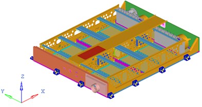
b) Inner structure model of the battery pack
Fig. 2FEA model of the battery pack and its inner battery sets
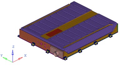
a) FEA model of the battery pack
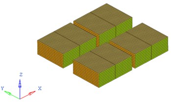
b) FEA model of the inner battery sets
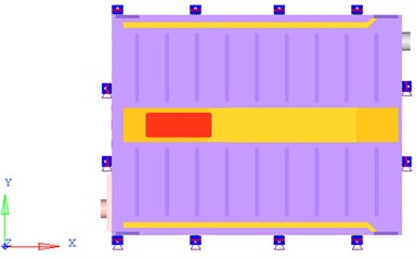
Similar to [4, 6-8], as an important load-condition in structure analysis and optimization for battery pack, restrained modal analysis is studied in this work. As the boundary condition shown in Fig. 3, 6 freedoms of each connecting position between battery pack bottom plate and the vehicle body are constrained.
Fig. 3Boundary condition of battery pack FEA model
A higher basic frequency (1st order restrained modal frequency) of battery pack can make it avoid the resonance with the vehicle [11], which is concerned most in this work. The first 20 order restrained frequencies and corresponding positions of vibration are illustrated in Table 1. Fig. 4 demonstrates the vibration mode of the first order frequency.
Besides, limited driving conditions of vehicles, such as frontal-collision and side-collision happened in a very short time, would cause super large acceleration acting on all the components [11]. For the sake of battery safety, the battery pack should not happen to crack under such transient shock, which means stress in the battery pack should not exceed the material tensile limit. Consequently, in this research, according to the regulations described in Chinese Automobile industry standard – General Requirement of Traction Battery Enclosure for Electric Vehicles (QC/T 989-2014), transient shock response of the battery pack under 40 g acceleration acted along its -axis and -axis in 6 ms, is concerned [12]. The loading process of acceleration excitation is shown in Fig. 5.
Table 1The first 20 order restrained frequencies and corresponding positions of vibration of the battery pack
Order | Frequency / Hz | Position |
1 | 38 | Entirety |
2 | 43 | Entirety |
3 | 50 | Bottom plate |
4 | 50 | Bottom plate |
5 | 50 | Bottom plate |
6 | 51 | Bottom plate |
7 | 51 | Bottom plate |
8 | 52 | Bottom plate |
9 | 54 | Bottom plate |
10 | 55 | Bottom plate |
11 | 56 | Bottom plate |
12 | 59 | Entirety |
13 | 67 | Bellows |
14 | 71 | Cover |
15 | 72 | Cover |
16 | 73 | Cover |
17 | 76 | Entirety |
18 | 76 | Entirety |
19 | 76 | Bottom plate |
20 | 77 | Bottom plate |
Fig. 4The vibration mode of first order frequency of the battery pack
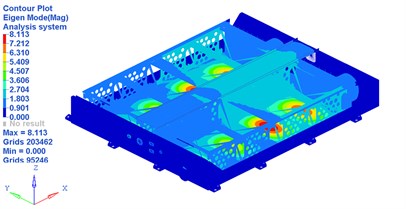
a) Main view of the vibration mode of first order frequency
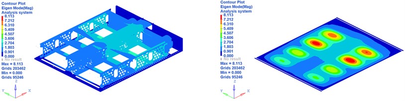
b) Inner view of the vibration mode of first order frequency
Through the FEA results displayed in Fig. 6, it is easy to find that the maximum von Mises stresses in battery pack -axis and -axis transient shock cases are both above 380 MPa, the tensile limit of steel. Therefore, security risk exists in this battery pack, and a redesign is necessary.
Fig. 5The loading process of acceleration excitation in 6 ms
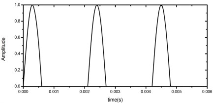
Fig. 6FEA results of x-axis and y-axis transient shock on the battery pack
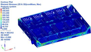
a) FEA results of -axis transient shock
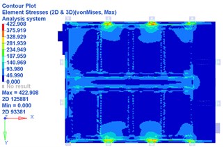
b) FEA results of -axis transient shock
3.2. Definition of optimization problem
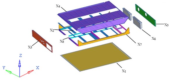
An excellent battery pack structure design should meet all of the mechanical performance requirements, in conjunction with lighter weight for energy-saving and mileage elongation consideration. Of all the mechanical properties, its first order restrained natural frequency ought to be as high as possible to avoid the resonance with the vehicle. Therefore, the basic frequency is maximized and at the same time the structural mass is minimized, whilst maintaining certain levels of other transient shock response indices along its -axis and -axis as mentioned. In this study, thicknesses of seven panels and one beam set in Fig. 7 are selected as the design variables whose ranges are all from 0.5 mm to 1.5 mm. The detailed information of these design variables are depicted in Table 2.
Fig. 7Illustration of design variables
The multi-objective size optimization problem for battery pack is thus specifically formulated as follows:
here, and are the total mass and first order restrained natural frequency of the battery pack, respectively; and are the global maximum von Mises stress in battery pack -axis and -axis transient shock cases.
Table 2The detailed information of eight design variables
Design variables | Name | Initial thickness (mm) |
Floor | 0.6 | |
Apron | 1.0 | |
Air intake plate | 0.8 | |
Cover | 0.8 | |
Air outlet plate | 0.8 | |
Air outlet chamber | 1.0 | |
Side wall | 0.8 | |
Beam set | 1.2 |
Fig. 8Flowchart of the proposed MOPSO procedure
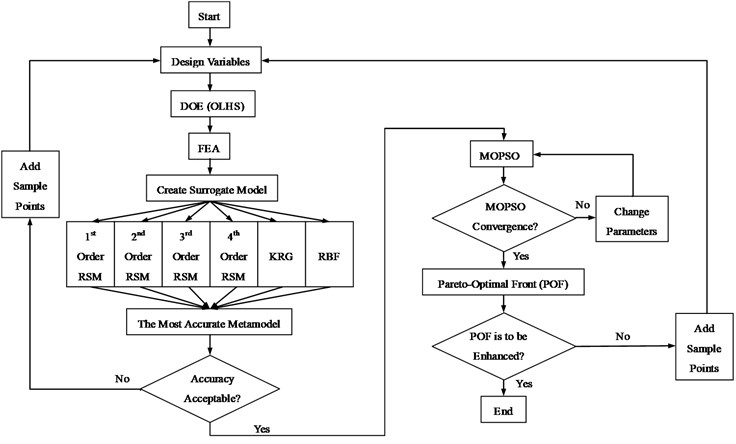
It takes a long time and a lot of hurdles to obtain FEA results used in the process of searching optimal mathematical solution especially for evolutionary algorithm often employed in multi-objective and multi-constraint optimization problem that involves large number of iterations. As an alternative, surrogate model is an effective way to formulate the relationship between the design variables and responses mathematically, which will also reduce the cost of computation. In general, for different problems, the precision of different kinds of surrogate models are not the same. In this investigation, three different surrogate models, PRS, KRG, and RBF are considered. Among these surrogates, the most accurate surrogate will be picked up to perform the multi-objective optimization design. To construct high accuracy surrogate, of many different DOE methods available, OLHS approach is selected to generate the training points in the design space here. In order to capture the global maximum dynamic stress in transient shock with nonlinear responses, 100 training points are generated first in this study [22, 24, 25, 33]. It should be noted that if the accuracy of metamodels based on the initial OLHS is unacceptable, the optimization procedure should be returned to the DOE step and more sampling points will be generated in addition to the existing sample points in which a max-min distance criterion is used for inserting the new points to the existing sample space [34]. Given the existing sample set ( samples), a new sample set ( samples) will be selected based on the max-min distance approach to maximize the minimum distance between any two sample points in the total sample set , i.e.:
where ( 1,…, ), (1,…, ).
To obtain the optimal multi-objective design of the battery pack, MOPSO algorithm, which has relatively fast convergence property and well-distributed Pareto frontier, is employed in this paper. More sampling points will also be added based on the max-min distance criterion mentioned above if the Pareto Optimal Frontier needs to be enhanced. For clarification, the proposed optimization procedure is summarized in the flowchart as Fig. 8.
4. Results and discussions
4.1. Selection and analysis of surrogate models
For the sake of choosing the most accurate and appropriate metamodels for multidiscipline problem in this study, the abovementioned three individual surrogates, namely, PRS (from 1st order polynomial to 4th order polynomial), RBF and KRG are constructed and used to run the optimization. Since the mass of the battery pack follows a linear relationship to the panel thicknesses, the 1st order PRS is adopted to model the weight. To assess the accuracy of these different surrogate schemes modeling the dynamic and transient shock responses of battery pack, 30 new validation points are also generated using the OLHS approach here. Three numerical estimators, namely R-square (R2), relative average absolute error (RAAE) and relative maximum absolute error (RMAE) [31] are used to measure the accuracy of these metamodels, as given in Eqs. (12). The computational results are summarized in Table. 3.
Table 3Accuracy assessment for different metamodels
Response | Metamodels | R2 | RAAE | RMAE |
1st order restrained frequency (Hz) | 1st order PSM | 0.9476 | 0.1808 | 0.6200 |
2nd order PSM | 0.9902 | 0.0805 | 0.1938 | |
3rd order PSM | 0.9869 | 0.0926 | 0.2377 | |
4th order PSM | 0.9865 | 0.0936 | 0.2406 | |
KRG | 0.9795 | 0.0977 | 0.5329 | |
RBF | 0.9880 | 0.0751 | 0.4115 | |
Max. stress under -axis transient shock | 1st order PSM | 0.6308 | 0.4780 | 1.4144 |
2nd order PSM | 0.8335 | 0.3184 | 0.9471 | |
3rd order PSM | 0.8440 | 0.3180 | 0.8068 | |
4th order PSM | 0.8156 | 0.3380 | 0.9631 | |
KRG | 0.7881 | 0.3322 | 1.3287 | |
RBF | 0.7757 | 0.4066 | 1.0686 | |
Max. stress under -axis transient shock | 1st order PSM | 0.7746 | 0.3966 | 1.3593 |
2nd order PSM | 0.8926 | 0.2656 | 0.7967 | |
3rd order PSM | 0.8732 | 0.2948 | 0.6143 | |
4th order PSM | 0.8467 | 0.3258 | 0.8305 | |
KRG | 0.8809 | 0.2382 | 1.3066 | |
RBF | 0.9109 | 0.2053 | 1.2028 |
For the prediction of restrained basic frequency in this study, similar to [14], 2nd order RSM is the most accurate and appropriate surrogate model with the R2 value of 0.9902 and RAAE value of 0.0805, which indicates a good performance for overall design space. As for transient acceleration shock analysis, which has relatively high nonlinearity degrees, 3rd order RSM and RBF are the most suitable metamodels for maximum global stress prediction of battery pack under -axis and -axis transient shock, respectively.
4.2. Results of MOPSO
Fig. 9 depicts the final Pareto optimal frontier (POF) of the multi-objective optimization for the battery pack, where the settings of MOPSO are list in Table 4.
POF converges adequately after 100 generations. A clear convexity of the curve can be observed, which provides the alternative design space for designers. It is noted that the exploration of the Pareto sets is crucial to fully understand the solution space for the multi-objective optimization problems. The POF provides the designer with a range of optimal solutions for their further decision-making. In all these Pareto plots it is shown that the mass and restrained basic frequency strongly compete with each other, with the range of mass variation from 0.3235-0.3501 ton, alongside with the range of frequency variation from 36.09-31.88 Hz. Obviously, owing to the effect of the restraint of maximum stress response under acceleration shock on the design domain, after optimization, all the values of mass and restrained basic frequency in the Pareto optimal solutions are over and below the initial design, respectively. Specifically, if the designers pay more attention to the weight reduction, the solutions at the bottom right corner should be selected. While if the designers emphasize on restrained basic frequency, the solutions at the top left corner will be considered.
Fig. 9Pareto optimal frontier (POF) and knee point of MOPSO
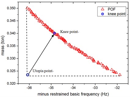
Table 4Parameter setting of MOPSO
Parameters of MOPSO | Value |
Population size | 100 |
External archive size | 100 |
Inertial weight | 0.73 |
Personal learning coefficient | 1.50 |
Global learning coefficient | 1.50 |
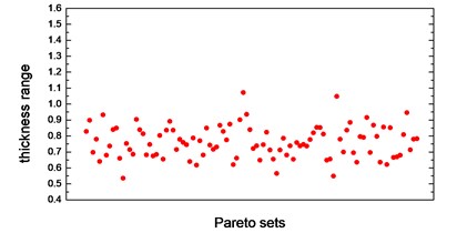
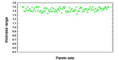
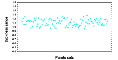
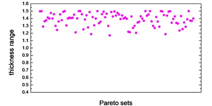
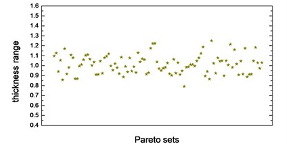
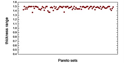
Thickness variation range of these eight design variables in Pareto optimal solution set is illustrated from Fig. 10(a) to Fig. 10(h). Apparently, from the eight variables, the thicknesses of the floor are distributed relatively uniform and almost occupied the whole variable space. That is because of the floor has a large surface area compared to other parts, which makes the total battery pack mass very sensitive to this floor thickness change. With the function of battery fixing for fear of its up-and-down movement in the pack, apron set is thinner, and has a size change basically between 0.5 to 1mm, since in this study we do not consider the maximum stress response under -axis acceleration transient shock. Air intake plate, air outlet plate and air outlet chamber are relatively thicker with the size no less than 1.0 mm in order to meet the stress requirement in -axis acceleration shock. For the sake of improving the 1st order restrained natural frequency, cover thickness should not less than 1.0 mm. The eighth design variable, namely, the thickness of the beam set, almost keeps 1.5 mm which is the upper bound of design variables in all Pareto optimal solutions for considering the reinforcement and connection functions of these beams.
Fig. 10Thickness range of eight design variables in Pareto sets after optimization
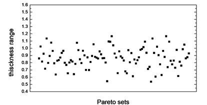
a) Thickness range of floor in Pareto sets
b) Thickness range of apron in Pareto sets
c) Thickness range of air intake plate in Pareto sets
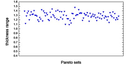
d) Thickness range of cover in Pareto sets
e) Thickness range of air outlet plate in Pareto sets
f) Thickness range of air outlet chamber in Pareto sets
g) Thickness range of side wall in Pareto sets
h) Thickness range of beam set in Pareto sets
To select the most apposite and the best trade-off optimization scheme, Knee Point, as a normalization to determine the accuracy improvement of Minimum Distance, mathematically given as below, allows us determining a most satisfactory solution from Pareto set [33]:
where is the number of the objective components, is the th objective value in the th Pareto solution, is the distance from knee point to an “utopia point”.
Compared with the initial design, it seems that the MOPSO knee point in this study deteriorate both of the two objectives (increase the mass and reduce the restrained basic frequency), which seems that our optimization study is meaningless. Actually, as above-mentioned, considering the restraint of maximum stress response under -axis and -axis acceleration shock, it is inevitably to increase the total mass of the battery pack to increase its strength, but simultaneously cause the basic frequency reduction. Our optimization study is just based on this situation. As shown in Fig. 9, frequency variation range in Pareto optimal solution is not much, just between 31.88-36.09 Hz, and the lower bound 31.88 Hz is over 30 Hz which is satisfactory for automotive devices [11]. Taking account of the lightest weight optimization scheme corresponding to restrained basic frequency is 31.88 Hz, this scheme is also meaningful and useful which should be selected as an alternative alongside with the Knee Point. The validation results of the two alternative optimum schemes using FEA, and their comparison with baseline are summarized in Table 5. There is small difference between the metamodel and FEA results as shown in Table 5. Both of the two schemes satisfy all these two stress response constraints presented. Nevertheless, it is noted that the Max. stress response under y-axis acceleration shock of Knee Point scheme has been pushed to the boundary of the constraint after optimization, which could lead to an unreliable solution if any perturbation of design variables presents.
Table 5Comparison between baseline and MOO optimal design
Description | Baseline | Optimization scheme 1 (knee point) | Optimization scheme 2 (minimum mass) | |||||
Metamodel | FEA | Difference | Metamodel | FEA | Difference | |||
Objectives | Mass | 0.3211 ton | 0.3402 ton | 0.3404 ton | –0.059 % | 0.3231 ton | 0.3253 ton | –0.68 % |
Restrained basic frequency | 38 Hz | 35.0 Hz | 34.8 Hz | 0.6 % | 31.9 Hz | 32.2 Hz | –0.93 % | |
Constraints | Max. stress under -axis shock | 402.8 MPa | 300.7 MPa | 311.9 MPa | –3.6 % | 364.0 MPa | 344.5 MPa | 5.7 % |
Max. stress under -axis shock | 422.9 MPa | 380.0 MPa | 367.5 MPa | 3.4 % | 378.2 MPa | 371.5 MPa | 1.8 % | |
Variables (thickness) | Floor | 0.6 mm | 1.14 mm | – | – | 0.56 mm | – | – |
Apron | 1.0 mm | 0.94 mm | – | – | 0.63 mm | – | – | |
Air intake plate | 0.8 mm | 1.49 mm | – | – | 1.39 mm | – | ||
Cover | 0.8 mm | 1.23 mm | – | – | 1.38 mm | – | – | |
Air outlet plate | 0.8 mm | 1.17 mm | – | – | 1.02 mm | – | – | |
Air outlet chamber | 1.0 mm | 1.50 mm | – | – | 1.20 mm | – | – | |
Side wall | 0.8 mm | 1.20 mm | – | – | 0.88 mm | – | – | |
Beam set | 1.2 mm | 1.50 mm | – | – | 1.43 mm | – | – | |
5. Conclusions
To carry and protect the lithium-ion power battery set equipped on electric vehicles, a battery pack is designed in this work. With the simplification of battery model as appropriate, FEA results of the baseline design show that the maximum von Mises stress responses under battery pack -axis and y-axis transient acceleration shock condition are both above the tensile limit of material. In addition to stress response, taking into account the mass and restrained basic frequency, a multi-objective and multi-constraints size optimization problem is necessary to carry out herein. The OLHS technique is first used to sample the points over the design space. Then, based on the limited sampling data obtained, different surrogate schemes, including PRS, KRG, and RBF, are established to relate the total mass, restrained basic frequency and global Max. stress in -axis and -axis shock cases to the design variables (thickness of panels and beams). It is found that 2nd order RSM, 3rd order RSM and RBF are the most accurate and appropriate metamodels for restrained basic frequency, global Max. stress under -axis and -axis shock condition, respectively. To minimize the total mass and simultaneously maximize the restrained basic frequency with the constraints of stress response, a multi-objective PSO (MOPSO) programme is implemented in this work. Owing to the restriction of global maximum stress response constraint, all of the optimal solutions in Pareto optimal frontier have heavier weight and lower frequency compared with baseline design. Two optimal schemes, namely, Knee Point and lightest weight, satisfied both of the stress constraint conditions, show great consistency with FEA results and can be selected as alternative improved schemes. These two battery packs will be fabricated and tested in our next work.
References
-
Beardmore P. Composite structures for automobiles. Composite Structures, Vol. 5, 1986, p. 163-176.
-
Liu Qiang, Lin Yongzhou, Zong Zhijian, Sun Guangyong, Li Qing Lightweight design of carbon twill weave fabric composite body structure for electric vehicle. Composite Structures, Vol. 97, 2013, p. 231-238.
-
Shahabeddin K. Mohammadian, Yuwen Zhang Thermal management optimization of an air-cooled Li-ion battery module using pin-fin heat sinks for hybrid electric vehicles. Journal of Power Sources, Vol. 273, 2015, p. 431-439.
-
Sang Lin, Li Zhiming, Pan Cheng Research on vibration characteristics of the electric vehicle battery pack. Electronic Test, Issue 12, 2011, p. 1-4.
-
Zhao Hongwei, Chen Xiaokai, Lin Yi Topology optimization of power battery cabin in electric vehicle. Journal of Jilin University, Vol. 39, Issue 4, 2009, p. 846-850.
-
Chu Yi, Liu Huafeng, Zhao Mingyu, Wang Gang, Lu Zhiyuan Modal analysis and optimization of EV fast-swap battery pack based on FEM. Manufacturing Automation, Vol. 34, Issue 12, 2012, p. 104-107.
-
Lu Zhiyuan, Zhang Weiguo, Zhao Mingyu, Zhang Hao The simulation and optimization of fast-swap battery pack of EV based on frequency sweeping. Modern Manufacturing Engineering, Vol. 5, 2013, p. 63-68.
-
Sang Lin, Ye Jiancheng, Dong Chen Modal analysis and experimental study for electric vehicle power battery pack. Manufacturing Automation, Vol. 35, Issue 11, 2013, p. 77-79.
-
Xie Qingxi, Zhang Nong, Zhang Bangji, Ji Jinchen Boundary condition handling approaches for the model reduction of a vehicle frame. Mechanical Systems and Signal Processing, Vol. 75, 2009, p. 123-137.
-
Paolo Ferabolia, Attilio Masini Development of carbon/epoxy structural components for a high performance vehicle. Composites Part B-Engineering, Vol. 35, 2004, p. 323-330.
-
Fabian Duddeck Multidisciplinary optimization of car bodies. Structural and Multidisciplinary Optimization, Vol. 35, 2008, p. 375-389.
-
General Requirement of Traction Battery Enclosure for Electric Vehicles, QC/T 989-2014. Ministry of Industry and Information Technology of the People’s Republic of China, Beijing, 2014.
-
Gao Yunkai, Sun Fang Multi-disciplinary optimization for front auto body based on multiple optimization methods. International Journal of Vehicle Design, Vol. 57, Issues 2-3, 2011.
-
Fang Jianguang, Gao Yunkai, Sun Guangyong, Li Qing Multiobjective reliability-based optimization for design of a vehicle door. Finite Elements in Analysis and Design, Vol. 67, 2013, p. 13-21.
-
Montgomery D. C. Designing and Analysis of Experiments. John Wiley and Sons, New York, 1996.
-
Hardy R. L. Multiquadric equations of topography and other irregular surfaces. Journal of Geophysical Research, Vol. 76, 1971, p. 1905-1915.
-
Sacks J., Welch W. J., Mitchell T. J., Wynn H. P. Design and analysis of computer experiments. Statistical Science, Vol. 4, 1989, p. 409-423.
-
Song X. G., Jung J. H., Son H. J., Park J. H., Lee K. H., Park Y. C. Metamodel-based optimization of a control arm considering strength and durability performance. Computers and Mathematics with Applications, Vol. 60, 2010, p. 976-980.
-
Sayed Ahmed Imran Bellary, Afzal Husain, Abdus Samad Effectiveness of meta-models for multi-objective optimization of centrifugal impeller. Journal of Mechanical Science and Technology, Vol. 28, Issue 12, 2014, p. 4947-4957.
-
Kwon Hyungil, Yi Seulgi, Choi Seongim Numerical investigation for erratic behavior of Kriging surrogate model. Journal of Mechanical Science and Technology, Vol. 28, Issue 9, 2014, p. 3697-3707.
-
Wang Jixin, Shen Wanghao, Wang Zhongda, Yao Mingyao, Zeng Xiaohua Multi-objective optimization of drive gears for power split device using surrogate models. Journal of Mechanical Science and Technology, Vol. 28, Issue 6, 2014, p. 2205-2214.
-
Fang Jianguang, Gao Yunkai, Sun Guangyong, Xu Chengmin, Li Qing Fatigue optimization with combined ensembles of surrogate modeling for a truck cab. Journal of Mechanical Science and Technology, Vol. 28, Issue 11, 2014, p. 4641-4649.
-
Liang Xinhua, Lin Zhongqin, Zhu Ping Acoustic analysis of damping structure with response surface method. Applied Acoustics, Vol. 68, 2007, p. 1036-1053.
-
Xiao Zhi, Fang Jianguang, Sun Guangyong, Li Qing Crashworthiness design for functionally graded foam-filled bumper beam. Advances in Engineering Software, Vol. 85, 2015, p. 81-95.
-
Fang Jianguang, Gao Yunkai, Sun Guangyong, Zhang Yuting, Li Qing Crashworthiness design of foam-filled bitubal structures with uncertainty. International Journal of Non-Linear Mechanics, Vol. 67, 2014, p. 120-132.
-
Xu Pin, Yang Chengxing, Peng Yong, Yao Shuguang, Zhang Dehong, Li Benhuai Crash performance and multi-objective optimization of a gradual energy-absorbing structure for subway vehicles. International Journal of Mechanical Sciences, Vol. 107, 2016, p. 1-12.
-
Coello Carlos A., Pulido Gregorio Toscano, Lechuga Maximino Salazar Handling multiple objectives with particle swarm optimization. IEEE Transactions on Evolutionary Computation, Vol. 8, Issue 3, 2004.
-
Park J.-S. Optimal Latin-hypercube designs for computer experiments. Journal of Statistical Planning and Inference, Vol. 39, 1994, p. 95-111.
-
Hickernell F. J. A generalized discrepancy and quadrature error bound. Mathematics of Computation, Vol. 67, 1998, p. 299-322.
-
Zhang Weiguo, Liu Yuan Main factor sensitivity analysis based on response surface model updating of port crane structure. Journal of Coastal Research, Vol. 73, 2015, p. 166-172.
-
Jin R., Chen W., Simpson T. W. Comparative studies of metamodelling techniques under multiple modelling criteria. Structural and Multidisciplinary Optimization, Vol. 23, 2001, p. 1-13.
-
Eberhart R., Kennedy J. A new optimizer using particle swarm theory. Proceedings of the 6th International Symposium on Micro Machine and Human Science, Nagoya, Japan, 1995.
-
Sun Guangyong, Li Guangyao, Zhou Shiwei, Li Hongzhou, Hou Shujuan, Li Qing Crashworthiness design of vehicle by using multiobjective robust optimization. Structural and Multidisciplinary Optimization, Vol. 44, 2011, p. 99-110.
-
Johnson M. E., Moore L. M., Ylvisaker D. Minimax and maximin distance designs. Journal of Statistical. Planning and Inference, Vol. 26, 1990, p. 131-148.
Cited by
About this article

This work is supported by The National Natural Science Foundation of China (51205023, 51275040) and The National Key Technology R&D Program of China (2014BAG02B02).
