Abstract
The drum shearer is one of the main equipments of the long-wall mining system. A typical condition to adjust the hauling and drum speeds is when the drum load exceeds the allowable value due to the hardness increase of the coal seam. Two schemes are utilized in this condition herein: (1) increasing the drum speed directly and maintaining the hauling speed; (2) decreasing the hauling speed firstly, then increasing the drum speed, finally increasing the hauling speed to the original value. The electromechanical dynamic model is firstly constructed for the Cutting Transmission System, and then the electromechanical dynamic analysis is conducted with both schemes, discovering that: the first scheme is quicker but may bring instability; the second is stable but slower; the resonance in frequencies obtained in different meshing conditions can be excited at the same time. At last, some advices are given for the development of the speed control strategies and mechanical design of the unmanned long-wall shearer.
1. Introduction
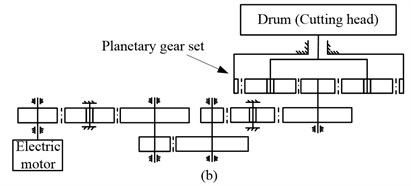
Long-wall mining has been the dominant coal mining method for decades [1] and the drum long-wall shearer as shown in Fig. 1(a) is one of the main equipment’s of the Long-wall mining system. The cutting transmission system of the long-wall shearer is composed of the motor, the gear transmission system, and the drum (cutting head) as shown in Fig. 1(b). The power source of the cutting transmission system is usually the triple-phase asynchronous induction motor without control at present, that is, the rotating speed of the drum cannot be adjusted as expected. The hauling speed is usually reduced when the drum load exceeds the allowable value, as a result in decrease of coal production for the mining systems. To overcome this difficulty, the drum rotating speed is designed to be adjustable and the direct torque control (DTC) induction motor is chosen as the power source of the drum driving system for the unmanned long-wall shearer.
Fig. 1Appearance
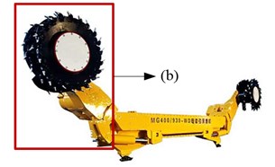
a) Drum driving system
b) Long-wall shearer
The cutting transmission chain is so long with several parallel-axis gears and a stage of planetary gear set, moreover, the drum load is heavy with strong impact and large fluctuation, so the cutting transmission system is a weak part of the shearer. For the unmanned shearer, the drum rotating speed and hauling speed should be adjusted jointly when the drum load increases or due to requirements of the mining process. More attention should be paid to the variable speed process that can affect the reliability and dynamic performance of the cutting transmission system of the unmanned long-wall shearer. Therefore, it is essential to conduct an electromechanical dynamic analysis for the cutting transmission system of the unmanned long-wall shearer to investigate the dynamic characteristics and electrical characteristics under the variable speed process, which can provide some guidance to make optimal speed control strategy and improve the reliability and dynamic performance of the cutting transmission system of the unmanned long-wall shearer.
The rotating speed of the cutting transmission system is variable for the unmanned long-wall shearer, and the generalized coordinate of the rotor in the electric motor model is usually angular displacement, so a dynamic model of variable speed process is needed for the gear transmission system and the generalized coordinates in the dynamic model should be angular displacements to connect the dynamic model to the electric motor model conveniently. The planetary gear set is one of the key parts of the gear transmission system because it is at the low-speed stage under heavy load and experience more probability of damage. Many dynamic models for planetary gear sets have been proposed in the literature [2-5]. These models [2-5] are proposed to mainly investigate the vibration properties of gear transmission systems and the vibratory translational and angular displacements [2, 4] are usually chosen as general coordinates. Therefore, these models [2-5] just can be used in vibration analysis of transmission systems at a stable mean angular velocity with small fluctuation, not for variable speed processes. A translational-torsional dynamic model of variable speed process was proposed for the herringbone planetary gear set in the reference [6]. In this dynamic model, the translational and angular displacements are chosen as the generalized coordinates, moreover, the meshing stiffness and profile error excitation are variable with the angular displacements of the herringbone planetary gear set. In this study, a torsional dynamic model of variable speed process for the spur planetary gear set [7] is utilized that is simplified from the model in [6]. In the dynamic model of the planetary gear set [7], the angular displacements chosen as the generalized coordinates, so it is convenient to be connected to the electric motor model to construct the electromechanical dynamic model.
Some investigations have been conducted for the electromechanical dynamic analysis of the motor-gear system in previous literature [8-15]. The steady-state model of electric motor is utilized in [8, 9, 12, 14], while in [10, 11, 13] the dynamic model of the motor is utilized. These studies [8-13] mostly focus on the parallel-axis gear pairs except the literature [14, 15]. In these investigations [8-15], only the literature [14, 15] focuses on the variable speed process. However, the dynamic model of the planetary gear set in [14, 15] is constructed based on the models in [3, 16, 17] by modifying the meshing stiffness according to the mean angular velocity. The variation of the mean rotating speed of gear transmission must be determined in advance, while, most of time, the rotating speed is usually unknown before the electromechanical dynamic model is simulated.
The cutting speed and hauling speeds usually need to be adjusted in two conditions: (1) when the mining process requires; (2) when the drum load exceeds the allowable value. Usually, the second condition may bring more damage to the shearer, so more attentions should be paid to it. The drum load can be reduced by adjusting the cutting speed or hauling speed, for example, increasing the drum rotating speed or decreasing the hauling speed, based on the calculation formula of the pick cutting force [18]. The calculation of the drum load will be depicted in Section 5. Two speed adjusting schemes are utilized herein: (1) increasing the drum speed directly and maintaining the hauling speed; (2) decreasing the hauling speed firstly, then increasing the drum speed, finally increasing the hauling speed to the original value.
In this study, the DTC induction motor is chosen as the power source of the cutting transmission system. The induction motor is controlled as shown in [19]. An electromechanical dynamic model for the drum driving system is constructed including the DTC induction motor, the gear transmission system, and the drum. The calculation of the drum load is depicted in detail, and then, based on it, two kinds of speed adjusting schemes are proposed. Next, the electromechanical dynamic characteristics of the drum driving system are simulated under these two variable speed processes. The advantages and disadvantages of this two speed adjusting schemes are discussed in detail base on the simulation. At last, some advices are given to develop the speed control system for the unmanned long-wall shearer.
2. Electromechanical dynamic model of the drum driving system
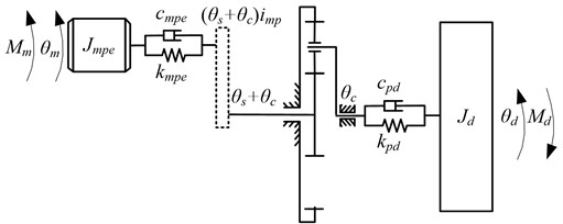
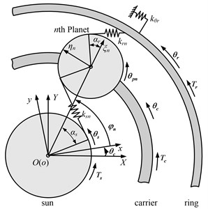
The drum driving system is composed of the DTC induction motor, the gear transmission system, and the drum (cutting head) as shown in Fig. 1(b). In this paper, an electromechanical dynamic model of the drum driving system is constructed including the electric motor, the gear transmission system, and the drum as shown in Fig. 2. The gear transmission system is a long chain with a series of parallel-axis gears and a stage of planetary gear set. To simplify the electromechanical dynamic model, the rotary inertias of the parallel-axis gear pairs and electric motor are equivalent to the motor rotor axis (). and denote the torsional stiffness and damping of the coupling between the electric motor and the gear transmission respectively; are the rotary inertia of the drum; and are the torques acting on the electric motor rotor and drum respectively; and are the angular displacements of the electric motor rotor and drum respectively; , and are the damping and stiffness of the connection between the carrier of the planetary gear set and drum; imp is the transmission ratio of the parallel-axis gear pairs. The angular displacements of the sun is measured in the moving coordinate system, so the angular displacements of the sun in the static coordinate frame is as shown in Fig. 2.
Fig. 2Electromechanical dynamic model of the drum driving system
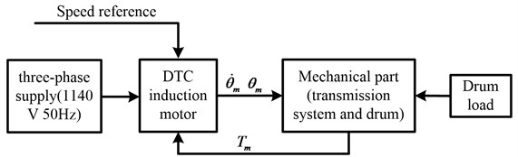
The electromechanical dynamic model is constructed as shown in Fig. 3, including three main parts: the DTC induction motor, the mechanical part (the gear transmission system and the drum), and the drum load model. The DTC induction motor is depicted in detail in reference [19]. The dynamic model of the mechanical part including the planetary gear set and drum will be depicted in detail following.
Fig. 3Block diagram of the electromechanical dynamic model of the drum driving system
A torsional dynamic model of variable speed process for the spur planetary gear set [7] is utilized in this study, which is simplified from the translational-torsional dynamic model of variable speed process for the herringbone planetary gear set in [6]. The angular displacement is chosen as the generalized coordinates in this model, so this model is convenient to be connected to the electric motor model for electromechanical dynamic analysis. In Fig. 4, three kinds of coordinate systems are constructed: (1) the static coordinate system ; (2) the moving coordinate system rotating with carrier; (3) the moving coordinate system on ,…, and is the number of planet) rotating with the carrier, where -axis is in the radial direction and -axis is in the tangential direction. Angular displacements (, ) are assigned to the sun and ring respectively, which are measured in the moving coordinate system . is the angular displacement of the carrier which is measured in the static system . is the angular displacement of the th planet which is measured in the moving coordinate system . [, ,, ,…, ] are chosen as the generalized coordinates to construct the dynamic model of the planetary gear set. is the position angle of the theoretical center of th planet, where . is the torsional supporting stiffness of the ring which is provided by gearbox house because the ring is usually fixed on the gearbox house. and is the torque acting on the sun and carrier. is the torque acting on the ring gear which is provided by the gearbox house, where .
Fig. 4Dynamic model of the planetary gear set
The planetary gear set is firstly transformed into parallel-axis external and internal gear pairs in the moving coordinate system to obtain the meshing forces, and then the Newton’s law in non-inertial coordinate system [3] is utilized to obtain the equations of motion of the spur planetary gear set as shown in Eq. (1):
In Eq. (1), is the planet distribution radius. (, ) denotes the meshing force of the th transformed external () and internal () spur gear pair in -direction respectively. The calculation of is depicted detailedly in [6] for the herringbone planetary gear set, while for the spur planetary gear set, the is calculated by set the helix angle to be zero.
The torque acting on the sun () and carrier () are calculated as Eqs. (2) and (3). The differential equation of the drum is derived as Eq. (4). Eqs. (2-4) and Eq. (1) are combined to construct the dynamic model of the mechanical part including the gear transmission system and drum. The torque acted on the motor () by the mechanical part is calculated by Eq. (5):
The differential equations of the mechanical part (including the gear transmission system and the drum) are made into s-function and connected to the DTC induction motor to construct the electromechanical dynamic model of the drum driving system as shown in Fig. 3. The drum load model will be depicted in next section
3. Calculation of the mean drum load
Usually, the drum load can be simulated by summing the mean drum load and random fluctuation, what is more, the random fluctuation is positively correlated with the mean drum load. To simplify the calculation, the mean load is used to reflect the trend of the realistic drum load. This simplification can be found in a lot of literature [20-23], in which the cutting forces are usually the mean cutting force.
3.1. Calculation of the mean cutting force of the single pick
The Goktan’s [18] semi-empirical formula as shown in Eq. (6) is utilized to calculate the mean cutting force () herein:
The attack angle (, degrees) and the friction angle between the pick and coal (, degrees) are considered as shown in Fig. 5.
Fig. 5Pick acting symmetrically on a buttock of rock [18]
![Pick acting symmetrically on a buttock of rock [18]](https://static-01.extrica.com/articles/17724/17724-img6.jpg)
In Eq. (6), is the tensile strength of the coal or rock (Pa), is the mean cutting depth (m) of the pick calculated by Eq. (7):
In Eq. (7), for the front drum, while for the back drum, is the diameter of the drum (m), is the height of the coal seam (m), is the amount of the picks in a single transversal line, is the drum speed (rad/s), is the hauling speed (m/min).
3.2. Calculation of the mean drum load
The cutting forces of all the picks are summed for the drum load. The mean drum load is calculated as Eq. (8):
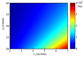
In Eq. (8), , , , and are the mean cutting force of the picks (N), drum radius from the drum centre to the pick top (m), amount of picks participating in cutting, and total amount of the picks on the th 1, 2, …, 12, as shown in Fig. 6) transversal line respectively. is the total amount of the transversal lines. Fig. 7 shows the variation of the mean drum load with the drum rotating speed and hauling speed.
Fig. 6Layout of the pick on the drum
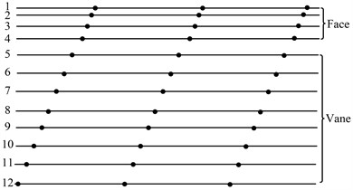
Fig. 7Variation trend of the mean drum load with the drum rotating speed (nd) and hauling speed (vq)
4. Speed adjusting schemes
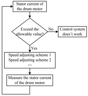
From Fig. 7, it is observed that the drum load decreases when the drum rotating speed increases or the hauling speed decreases. That is, when the drum load exceeds the allowable value, the shearer control system can reduce the drum load by increasing the drum rotating speed and decreasing hauling speed jointly or separately. How to control drum rotating speed and hauling speed in practical application is what to be studied in the control strategy of the unmanned shearer. It is difficult to mount the torque sensor on the drum due to serious vibration and shock of the drum, so the stator current of the drum motor is used as the feedback signals of the shearer control system to reflect the drum load. The stator current used as feedback signals is not what directly measured from the stator, but the root mean square (RMS) of the stator current with low pass filtered. The flow diagram to adjust speeds is shown in Fig. 8 when the drum load exceeds the allowable value.
The drum load can be reduced by increasing the drum rotating speed and decreasing hauling speed jointly or separately. There are many combinations to adjust the drum rotating speed and hauling speed, that is, speed adjusting schemes. Two schemes are used when the drum load exceeds the allowable value in this study, including: (1) increasing the drum rotating speed directly and maintaining the hauling speed stable; (2) decreasing the hauling speed firstly, then increasing the drum rotating speed, finally increasing the hauling speed to the original value. In practical application, the hauling speed usually maintains stable to obtain maximum coal production, so the hauling speed does not change before and after the speed adjusting process in these two speed adjusting schemes.
Fig. 8Flow diagram to adjust speeds when the drum load exceeds the allowable value
The drum rotating speed is adjusted by changing the speed of driving motor, for the drum speed is proportional to the motor speed. The drum rotating speed is reflected by the motor speed in speed adjusting schemes. The speed adjusting schemes are shown in Fig. 9.
Fig. 9Schemes of adjusting the drum driving motor speed (nm) and hauling speed (vq)
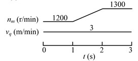
a) First strategy
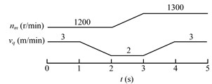
b) Second strategy
5. Electromechanical dynamic simulation and analysis
When the shearer cuts from soft coal seam to hard coal seam, the drum load may exceed the safety value of the unmanned long-wall shearer if the drum rotating speed and hauling speed are not adjusted. Therefore, the drum rotating speed and hauling speed should be adjusted when the drum load is found to be too high. Two kinds of speed adjusting schemes are proposed in Section 3. The electromechanical dynamic simulation is conducted for both the strategies.
Table 1Parameters of the cutting transmission system
Parameters | |
Electric motor | 3-pase DTC asynchronous induction motor, rated power 300 kW; Rated line voltage 1140 V, the initial rotating speed is 1200 r/min |
Mechanical system | 104 Nm/rad; 102 Nm/s·rad-1; 109 Nm/rad; 0 Nm/s·rad-1; 350 kg/m2; Planetary gear set: the teeth number of the sun, planet, and ring are 16, 24, and 64 respectively; the module is 9 mm |
The advantages and disadvantages of the schemes are analyzed based on the simulation. At last, some advices are given to develop the speed control strategy for the unmanned long-wall shearer. The parameters of the cutting transmission system are shown in Table 1. The simulation is conducted in MATLAB/Simulink. The DTC induction motor block in Simulink is chosen, and the model of mechanical part is written in -function, and then, they are connected for the complete model and simulated.
5.1. Electromechanical dynamic analysis for the first speed adjusting scheme
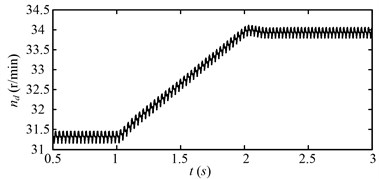
The rotating speed of the motor during the simulating time is shown in Fig. 10 for the first speed adjusting scheme. It is the transient process at the beginning of the simulating time. The rotating speed reaches to steady-state at about 0.5 s. This initial transient process will be ignored in the following analysis for the clarity of illustration in this study. The motor speed varies as the first speed adjusting scheme in Fig. 9(a). Fig. 11 shows the rotating speed of the drum. The variation trend of the drum rotating speed is same with that of the motor speed as shown in Fig. 11.
Fig. 10Rotating speed of the electric motor (nm) for the first speed adjusting scheme
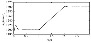
Fig. 11Rotating speed of the drum (nd) for the first speed adjusting scheme
The drum load for the first speed adjusting scheme is shown in Fig. 12. The drum load decreases obviously with the increase of the drum speed. The fluctuation of the drum load also decreases as the drum load decreases. Fig. 13 shows the dynamic meshing force of the sun-planet gear pair of the planetary gear set for the first speed adjusting scheme. The dynamic meshing force decreases as the drum load decreases, and the fluctuation of the dynamic meshing force also decreases. In a word, the drum load and dynamic meshing force can be reduced effectively by increase the drum rotating speed.
Fig. 12Drum load (Md) for the first speed adjusting scheme
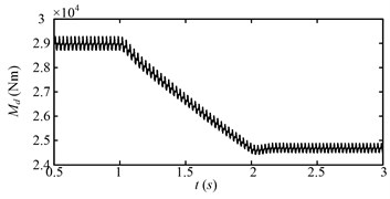
Fig. 13Dynamic meshing force (Fme) of the sun-planet gear pair of the planetary gear set for the first speed adjusting scheme
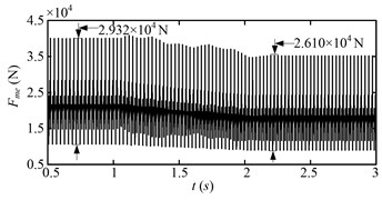
Fig. 14 shows the root mean square (RMS) of the a-phase stator current of the driving motor of the drum that is low pass filtered with cut-off frequency of 20 Hz. At beginning (0.5-1 s), the stator current is stable, because the motor speed is steady. During 1-2 s, the stator current increases obviously. During this period, the drum motor speed increases, therefore, larger electromagnetic torque is needed to accelerate the motor, which leads to the obvious increase of the stator current. After 2 s, when the acceleration process is over, the stator current decreases to less than the initial value of 0.5-1 s, because the drum load after 2 s is smaller than that during 0.5-1 s. The RMS of the stator current is positive correlation to the drum load except the acceleration process. Not only the drum load but also the acceleration torque needs to be balanced by the electromagnetic torque of the motor during the acceleration process.
From the above analysis, the first speed adjusting scheme is proved to be an effective way to reduce the drum load and dynamic meshing forces. However, some problems exist in the first speed adjusting scheme. The RMS of the stator current is usually utilized as the feedback signal to reflect the drum load for the shearer control system. The drum load is assumed to exceed the allowable value at beginning (0.5-1 s), that is, the stator current exceeds the allowable value at the beginning (0.5-1 s).
Fig. 14Roots mean square of a-phase stator current (isarms) of the DTC induction motor (cutting motor) with low-pass (20 Hz) filtered for the first speed adjusting scheme
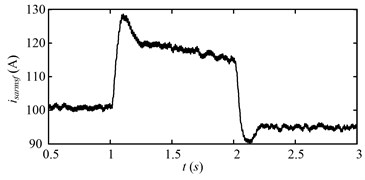
Then, the drum rotating speed is increased to reduce the drum load at 1 s due to the effect of the shearer control system as shown in Fig. 8. However, if the drum rotating speed increases directly to reduce the drum load, the stator current will exceed the allowable value as shown in Fig. 14, as a result, the control system will wrongly consider the drum load increases and accelerate the motor to a larger speed. This circulation will make the drum rotating speed increase unceasingly, that is, the control system is unstable. If the stator current does not exceed the allowable value during the speed adjusting process (including the drum speed acceleration process), the control is stable.
5.2. Electromechanical dynamic analysis for the second speed adjusting scheme
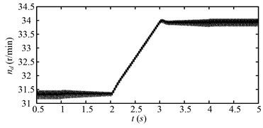
Fig. 15 shows the rotating speed of the motor during the simulating time for the second speed adjusting scheme. The motor speed varies as the second speed adjusting scheme in Fig. 9(b). Fig. 16 shows the rotating speed of the drum. The variation trend of the drum speed is same with that of the motor speed. The fluctuation of the drum speed decreases or increases as the drum load decreases or increases as shown in Fig. 17. The drum load for the second speed adjusting scheme is shown in Fig. 17.
Fig. 15Rotating speed of the electric motor (nm) for the second speed adjusting scheme
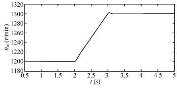
Fig. 16Rotating speed of the drum (nd) for the second speed adjusting scheme
At beginning (0.5-1 s), the drum load is stable, because the drum rotating speed and hauling speed is steady. During 1-2 s, the drum load decreases obviously as the hauling speed decreases. During 2-3 s, the drum load decreases continually as the drum rotating speed increases. During 3-4 s, the drum load increases as the hauling speed increases. After 4 s, when the variable speed process is over, the drum load decreases to less than the initial value (0.5-1 s). The drum load decreases obviously after the variable speed process, so does the fluctuation of the drum load. Fig. 18 shows the dynamic meshing force of the sun-planet gear pair of the planetary gear set for the second speed adjusting scheme. The dynamic meshing force decreases as the drum load decreases, and the fluctuation of the dynamic meshing force also decreases. In a word, the drum load and dynamic meshing force can be reduced effectively by the second speed adjusting scheme.
Fig. 17Drum load (Md) for the second speed adjusting scheme
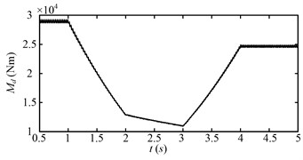
Fig. 18Dynamic meshing force of the sun-planet gear pair (Fme) of the planetary gear set for the second speed adjusting scheme
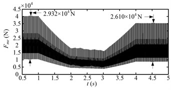
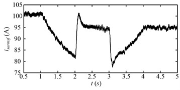
Fig. 19 shows the root mean square (RMS) of the a-phase stator current of the driving motor of the drum that is low pass filtered with the cut-off frequency of 20 Hz. At beginning (0.5-1 s), the stator current is stable, because the speed of the drum motor, hauling speed, and drum load are steady. During 1-2 s, the stator current decreases obviously, because the drum load decreases due to the decrease of the hauling speed. During 2-3 s, the stator current increases obviously. During this period, the speed of the drum motor increases, thus, larger electromagnetic torque is needed to accelerate the rotor, which leads to the obvious increase of the stator current.
At 3 s, when the acceleration process of the drum motor is over, the stator current decreases obviously. During 3-4 s, the stator current increases, because the drum load increases due to the increase of the hauling speed. After 4 s, when the variable speed process is over, the stator current decreases to less than the initial value (0.5-1 s), because the drum load after 4 s is smaller than that during 0.5-1 s.
Fig. 19Roots mean square of a-phase stator current (isarms) of the DTC induction motor (drum driving motor) with low-pass (20 Hz) filtered for the second speed adjusting scheme
From the above analysis, the second speed adjusting scheme is also proved to be an effective way to reduce the drum load and dynamic meshing forces, but the speed adjusting time is longer. The RMS of the stator current is usually utilized as the feedback control signal to reflect the drum load for the shearer control system. The drum load is assumed to exceed the allowable value at beginning (0.5-1 s), that is, the stator current exceeds the allowable value at the beginning (0.5-1 s), then the drum rotating speed and hauling speed are adjusted during 1-4 s due to the effect of the shearer control system as shown in Fig. 8. The hauling speed is reduced to decrease the drum load before accelerating the drum rotating speed, therefore, the stator current is under the allowable value all the time during the variable speed process. To this aspect, the control system with the second speed adjusting scheme is stable.
5.3. Comparison of torsional vibration characteristics between scheme 1 and 2
To compare the torsional vibration characteristics between scheme 1 and 2, the drum angular acceleration in time domain is given in Fig. 20, and the time frequency maps are given in Fig. 21 (0-8000 Hz) and Fig. 22 (0-600 Hz). For the scheme 1, the drum speed is increased directly from 1 to 2 s. The fluctuating amplitude of the angular acceleration decreases after the variable speed process, because the drum load decreases as shown in Fig. 12. For the scheme 2, the drum load decreases from 1 to 2 s and increases from 3 to 4 s, because of the hauling speed decreases and increases, correspondingly, the fluctuating amplitude of the angular acceleration decreases and increases. During 1-2 s in Fig. 20(a) and 2-3 s in Fig. 20(b), the drum speed increases, that is, these durations are unstable processes.
Fig. 20Drum angular accelerations of scheme 1
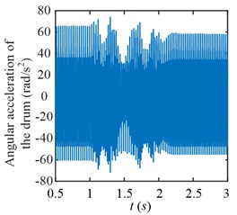
a) Scheme 1
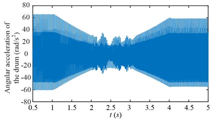
b) Scheme 2
Fig. 21Time frequency maps of the drum angular accelerations of scheme 1
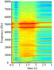
a) Scheme 1
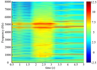
b) (0-8000 Hz)
Fig. 22Time frequency maps of the drum angular accelerations of scheme 1
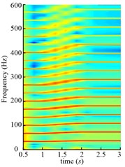
a) Scheme 1
b) (0-600 Hz)
From above analysis, we can see both schemes are unstable processes, so the time-frequency analysis is conducted. The amplitudes around 5110 Hz and 4576 Hz stand out along the time axis, because the 153rd and 137th order meshing frequency come across the natural frequency. The one-tooth-contact and two-teeth-contact alternate in gear system, so different natural frequencies can be obtained in different meshing conditions. Two kinds of natural frequencies are shown in Table 2.
Table 2Two kinds of natural frequencies obtained in different meshing conditions (Hz)
1st | 2nd | 3rd | 4th | 5th | 6th | 7th | 8th | 9th | |
1 | 0 | 19 | 87 | 1003 | 2341 | 2341 | 2535 | 5109 | 22696 |
2 | 0 | 24 | 66 | 710 | 1532 | 1532 | 1706 | 4573 | 23318 |
Though these two kinds of natural frequencies are obtained in different meshing conditions, the resonance of both 8th frequencies are excited as shown in Fig. 21. Therefore, all the natural frequencies obtained in different meshing conditions should be paid attention to for the gear transmission system, and it is not enough to just consider the natural frequency with the mean meshing stiffness. Compared Fig. 21(a) and (b), the amplitude in Fig. 21(b) is smaller than that in Fig. 21(a) during variable speed process (1-2 s in Fig. 21(a), 2-3 s in Fig. 21(b)), because the drum load is smaller in Fig. 21(b). The partial enlarged details of Fig. 21 in 0-600 Hz are shown in Fig. 22. The meshing frequency and its multiplications increase linearly during the variable speed process.
5.4. Experimental investigation
To validate the theoretical results, the scaled-down test rig is constructed. The overall scheme of the test rig is shown in Fig. 23. Three main parts are contained in test rig, including the power source, gear transmission system, and loading equipment. The power source is composed of the DTC converter and electric motor. The realistic cutting transmission is so large that it is nearly impossible to put the realistic cutting transmission on the test rig, so the gear transmission is composed of a two-stage parallel-axis gear reducer and a planetary gear reducer to simulate the realistic cutting transmission.
Fig. 23Overall scheme of the test rig
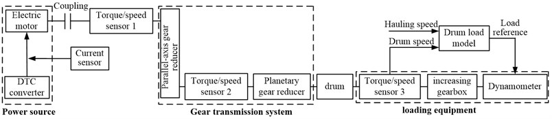
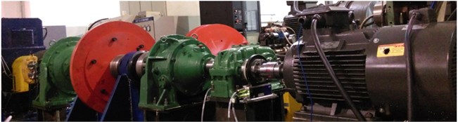
The loading equipment is composed of a dynamometer, an increasing gearbox, and a torque/speed transducer. The torque/speed transducer 1 is used to measure the input torque/speed of parallel-axis gear reducer estimate the dynamic meshing force of the high-speed stage of parallel-axis gear reducer. The torque/speed transducer 2 is used to measure the input torque/speed of the planetary gear set to estimate the dynamic meshing force of the sun-planet gear pair of the planetary gear set. The torque/speed transducer 3 is used to measure the realistic drum load and speed. The Photo of the test rig is shown in Fig. 24.
Fig. 24Photo of the test rig
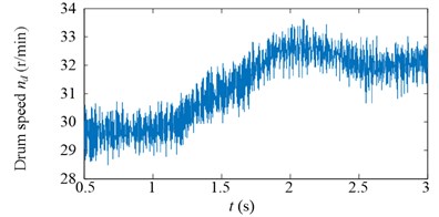
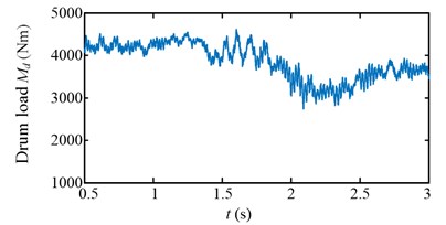
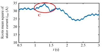
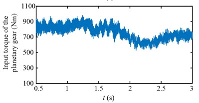
Experimental results in time domain of two speed adjusting schemes are shown in Fig. 25. For the first scheme, during 1-2 s, the drum speed increase from 29.8 r/min to 32.8 r/min in Fig. 25(a), while the drum load decrease from 4300 Nm to 3192 Nm in Fig. 25(c), the input torque of the planetary gear also decrease from 836 Nm to 629 Nm in Fig. 25(e). However, at the beginning of drum speed acceleration, the stator current is larger than the initial value as shown in the red ellipse C of Fig. 25(g). In brief, after the first speed adjusting process, the drum load, dynamic load of the transmission system, and the stator current all decrease.
Fig. 25Experimental results in time domain of two speed adjusting schemes
a)
b)
c)
d)
e)
f)
g)
h)
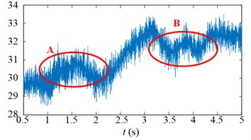
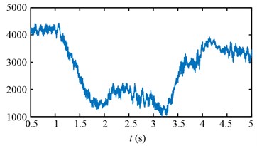
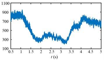
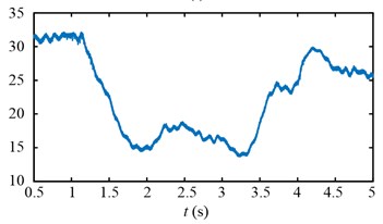
For the second scheme, during 1-2 s, because of the hauling speed decreasing from 3 to 2 m/min, the drum load decrease from 4300 Nm to 1413 Nm in Fig. 25(d), and the input torque of the planetary gear decrease from 836 Nm to 282 Nm in Fig. 25(f). The drum speed increase a little because the drum load decrease as shown in the red ellipse A of Fig. 25(b). During 2-3 s, the drum speed increase from 30 r/min to 32.6 r/min in Fig. 25(b), so the drum load and input torque of the planetary gear decrease continuously in Fig. 25(d, f). During 3-4 s, because of the hauling speed increasing from 2 to 3 m/min, the drum load increase from 1065 Nm to 3700 Nm in Fig. 25(d), and the input torque of the planetary gear increase from 213 Nm to 750 Nm in Fig. 25(f).
The drum speed decreases a little because the drum load increase as shown in the red ellipse B of Fig. 25(b). In brief, after the second speed adjusting process, the drum load, dynamic load of the transmission system, and the stator current all decrease, what’s more, the stator current doesn’t excess the initial value during the second speed adjusting process as shown in Fig. 25(h).
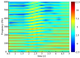
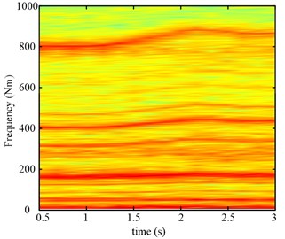
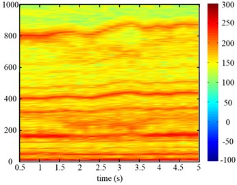
The time frequency maps of the input torque of the planetary gear are given in Fig. 26, which can reflect the system torsional vibration. During the variable speed process, the varying frequency components are found in Fig. 26, which has the same trend as the simulating results.
In a word, most of the simulating results are validated by the experimental results to confirm the usability of the simulating model.
Fig. 26Time frequency maps of the input torque of the planetary gear of two speed adjusting schemes
a)
b)
6. Conclusions
The drum shearer is one of the main equipments of the long-wall mining system that has been widely used in coal mining for decades. The rotating speed of the drum is usually not adjustable at present. The hauling speed is usually reduced when the drum load exceeds the allowable value, as a result in decrease of coal production for the mining systems. To overcome this difficulty, the drum rotating speed is designed to be adjustable and the direct torque control (DTC) induction motor is chosen as the power source of the cutting transmission system for the unmanned long-wall shearer. Therefore, the drum load can be reduced by adjust the drum rotating speed without decreasing the hauling speed. Two speed adjusting schemes are proposed when the drum load exceeds the allowable value including: (1) increasing the drum speed directly and maintaining the hauling speed; (2) decreasing the hauling speed firstly, then increasing the drum speed, finally increasing the hauling speed to the original value. More attention should be paid to the electrical and dynamic characteristics of the cutting transmission system for assessing and developing optimal control strategy. Both the schemes are analyzed and compared based on the electromechanical dynamic analysis of the drum driving system. Some conclusions are obtained for both of the schemes:
1) The first scheme is quicker, but the control system may be unstable. If the drum rotating speed is adjusted when the stator current exceeds the allowable value, the stator current of the acceleration process will be much larger than the allowable value, which leads to instability for the shearer control system. However, the control system is stable as long as the stator current does not exceed the allowable value during the speed adjusting process (including the drum speed acceleration process), when the drum rotating speed is adjusted just for satisfying the requirement of the mining process.
2) The second scheme is stable, because the stator current does not exceed the allowable value during the variable speed process (including the drum speed acceleration process). However, the adjusting time is longer, because both the drum speed and the hauling speed are adjusted, moreover, they are adjusted alternately.
3) The amplitude in the second scheme is smaller than that in the first scheme during variable speed process, because the drum load is smaller in the second scheme. The resonance in frequencies obtained in different meshing conditions can be excited at the same time, so all the natural frequencies obtained in different meshing conditions should be paid attention to for the gear transmission system, and it is not enough to just consider the natural frequency with the mean meshing stiffness.
The drum speed and hauling speed should be adjusted simultaneously to avoid the instability of the control system and shorten the adjusting time. The adjustment amounts for the drum rotating speed and hauling speed are decided by the electromechanical characteristic of the cutting transmission system and the drum load characteristic. The drum load is influenced by both the drum rotating speed and the hauling speed [18, 23, 24]. The coordination control of the drum rotating speed and hauling speed will be investigated in further study. In the mechanical design of the cutting transmission system, all the natural frequencies in different meshing conditions should be calculated and keep away from the meshing frequency as well as multiplications to avoid resonance.
References
-
Kingshott M., Graham M. Coal age-a longwall look at tomorrow. Coal Operators Conference, 1998, p. 343-351.
-
Kahraman A. Natural modes of planetary gear trains. Journal of Sound and Vibration, Vol. 173, Issue 1, 1994, p. 125-130.
-
Lin J., Parker R. G Analytical characterization of the unique properties of planetary gear free vibration. Journal of Vibration and Acoustics, Vol. 121, Issue 3, 1999, p. 316-321.
-
Guo Y., Parker R. G. Dynamic modeling and analysis of a spur planetary gear involving tooth wedging and bearing clearance nonlinearity. European Journal of Mechanics – A/Solids, Vol. 29, Issue 6, 2010, p. 1022-1033.
-
Kim W., Lee J. Y., Chung J. Dynamic analysis for a planetary gear with time-varying pressure angles and contact ratios. Journal of Sound and Vibration, Vol. 331, Issue 4, 2012, p. 883-901.
-
Liu C., Qin D., Lim T. C., Liao Y. Dynamic characteristics of the herringbone planetary gear set during the variable speed process. Journal of Sound and Vibration, Vol. 333, Issue 24, 2014, p. 6498-6515.
-
Liu C., Qin D., Liao Y. Electromechanical dynamic analysis for the drum driving system of the long-wall shearer. Advances in Mechanical Engineering, Vol. 7, Issue 10, 2015, p. 1-14.
-
Theodossiades S., Natsiavas S. Periodic and chaotic dynamics of motor-driven gear-pair systems with backlash. Chaos, Solitons and Fractals, Vol. 12, Issue 13, 2001, p. 2427-2440.
-
Khabou M. T., Bouchaala N., Chaari F., Fakhfakh T., Haddar M. Study of a spur gear dynamic behavior in transient regime. Mechanical Systems and Signal Processing, Vol. 25, Issue 8, 2011, p. 3089-3101.
-
Mezyk A. Minimization of transient forces in an electro-mechanical system. Structural Optimization, Vol. 8, Issue 4, 1994, p. 251-256.
-
Clerc G., Feki N., Velex P. Modeling of gear-motor dynamic interactions – applications to the detection of tooth faults by electric measurements. VDI-Berichte Nr. 2108, 2010. p. 941-953.
-
Bartelmus W. Mathematical modelling and computer simulations as an aid to gearbox diagnostics. Mechanical Systems and Signal Processing, Vol. 15, Issue 5, 2001, p. 855-871.
-
Feki N., Clerc G., Velex P. An integrated electro-mechanical model of motor-gear units – Applications to tooth fault detection by electric measurements. Mechanical Systems and Signal Processing, Vol. 29, 2012, p. 377-390.
-
Chaari F., Abbes M. S., Rueda F. V., Rincon A. F. D., Haddar M. Analysis of planetary gear transmission in non-stationary operations. Frontiers of Mechanical Engineering, Vol. 8, Issue 1, 2013, p. 88-94.
-
Qin D., Bai W., Zhang F. Study on dynamic characteristics of gear transmission system of wind turbine with varying load. VDI-Berichte Nr. 2199, 2013. p. 113-125.
-
Sika G., Velex P. Analytical and numerical dynamic analysis of gears in the presence of engine acyclism. Journal of Mechanical Design, Vol. 130, Issue 12, 2008, p. 124501-124502.
-
Sika G., Velex P. Instability analysis in oscillators with velocity-modulated time-varying stiffness –applications to gears submitted to engine speed fluctuations. Journal of Sound and Vibration, Vol. 318, Issues 1-2, 2008, p. 166-175.
-
Goktan R. M., Gunes N. A semi-empirical approach to cutting force prediction for point-attack picks. Journal of the South African Institute of Mining and Metallurgy, Vol. 105, 2005, p. 257-263.
-
Takahashi I., Toshihiko N. A new quick-response and high-efficiency control strategy of an induction motor. IEEE Transactions on Industry Applications, Vol. 22, Issue 5, 1986, p. 820-827.
-
Bao R. H., Zhang L. C., Yao Q. Y., Lunn J. Estimating the peak indentation force of the edge chipping of rocks using single point-attack pick. Rock Mechanics and Rock Engineering, Vol. 44, Issue 3, 2011, p. 339-347.
-
Bilgin N., Demircin M. A., Copur H., Balci C., Tuncdemir H., Akcin N. Dominant rock properties affecting the performance of conical picks and the comparison of some experimental and theoretical results. International Journal of Rock Mechanics and Mining Sciences, Vol. 43, Issue 1, 2006, p. 139-156.
-
Evans I. A theory of the cutting force for point-attack picks. Geotechnical and Geological Engineering, Vol. 2, Issue 1, 1984, p. 63-71.
-
Du C., Liu S., Cui X., Li T. Study on pick arrangement of shearer drum based on load fluctuation. Journal of China University of Mining and Technology (China), Vol. 19, Issue 1, 2009, p. 74-78.
Cited by
About this article

The authors would like to acknowledge the support and contribution from the State Key Lab of Mechanical Transmission, Chongqing University, China. This research was funded by the National Major Basic Research Program of China (Fundamental Research of Unmanned Mining Equipment Used for Dangerous and Deep Coal Seam, 973 Program, Grant No. 2014CB046304).
