Abstract
With considering the unbalance mass-fluid film bearings-rotor elements, a dynamics model for the nuclear half-speed 1000 MW saturated steam turbine with No. Dongfang HN1089 is constructed. By solving of the Reynolds Equation and the dynamics model, the oil pressure distribution and dynamic coefficients of the fluid film bearings, and the unbalance response of the rotor, are obtained. The method for evaluating the bending fault based on the dynamics model is proposed, in which the bending parameter is transformed as the unbalance mass. A case on the bending fault evaluation for HN1089 is carried out. The results show that the response sensitivity of HN1089 on the unbalance mass is about 1/6 that of the thermal power units with the same capacity (1000 MW); and it is difficult to decrease the excited response from the bending fault even to add the maximum unbalance mass. In actual, the removing stress in the partial zone and turning method are applied to deal with the HP-IP rotor bending fault, and the response of the repaired rotor is 0.033 m by the actual field test. The results show the model and the method for evaluating the bending fault are accurate and reasonable, which will provide the important theoretical guide for fast and accurately dealing with such bending fault in the steam turbine rotor system.
1. Introduction
Influenced by the main factors, like the small gap of the labyrinth seal in the steam turbine and the external excitation, the vibration response of the steam turbine rotor is easy to exceed the limit of the related standard requirement, which will lead to the rub-impact faults between the rotor and stator of the large turbine generator units [1, 2]. The severe rub-impact easily eventuate the bending fault and accident of the rotor [3, 4]. Conversely, the rotor bending will induce the more severe vibration response. So, the bending phenomenon has been paid more attention to research its mode of origin, disadvantage and maintenance methods. In these existed studies, for obtaining the influence of the rub-impact faults from the rotor bending on the vibration response of the bearing-rotor system, the rotor dynamic model was established, including the linear model [5-9] and nonlinear model [10-13]. For example, Ren Z. et al. presented a finite element model for a complex rotor-bearing system with coupled faults, such as the rub-impact and crack, and the results show that the responses of the rotor-bearing system increase due to the presence of the coupled fault [5]. With the Full rotor dynamic analysis, Jalali et al. explained that high speed rotors are vulnerable to vibrations resulting in the failure of the whole operating system [6]. For obtaining the better techniques of vibration control, Rosyid A. et al. presents how optimal control is applied to rotor-bearing-support systems in which the rotor finite element models have relatively large degrees of freedom [7]. Brouwer M. D. et al. developed a dynamic model for the ball bearing-rotor, and the EFEM and DEM were combined to investigate the dynamics of flexible shaft rotor systems [8]. Da Fonseca et al proposed a dynamic model that the transfer matrix method is used to predict bending critical speeds, and the model is applied in the analysis of hydro generator shaft lines [9].
In the nonlinear model respect, Zhang G. Y. et al. established a coupled nonlinear vibration model of the oil film force and electromagnetic force, and the dynamic stability and vibration response analysis for the 300 MW turbine generator are carried out [10]. Xu X. P. et al. studied the nonlinear responses of a rotor with dynamic and static eccentricities, and the effects of rotating frequency and initial static eccentricity on rotor shaft orbit and displacement spectra are acquired [11]. Zhang X. et al. proposed a comprehensive dynamic model and the dynamic behaviors (frequencies stiffness and dampness matrix, stability) of the ball bearing-rotor system were analyzed [12]. Zhang L. et al. established a coupled bending-torsional rotor-bearing system with rub-impact under electromagnetic excitation for hydraulic generating set and the influence of excitation current, mass eccentricity and electromagnetic torque in the system is investigated by taking use of numerical method [13].
With these models, the vibration response characteristics are acquired and the fault are monitored and predicted. But there is less reports in connection with solving this fault or proposing the maintenance methods on the bending fault. Most of the experiment studies also focused on the verification of the rotor dynamic model [14, 15], it is very lack of the bending fault evaluation and solution for the actual steam turbine units.
In the field test, there are two kinds of maintenance methods which can be applied to deal with the bending fault, as the straightening rotor and the turning unbalance mass of the rotor. The bending rotor maintained by these two methods can be applied in the actual engineering after the related dynamic balancing processing. Comparing the above methods, the rotor straightening is more dangerous, even lead to the rotor damage; and the turning imbalance mass of rotor is easier to carry out, and have the higher safety and less cost. But the common defect of the above methods is that it will expense much time and massive maintenance cost. So, in the power plant, the bending fault evaluation is very important, and the fault will be analyzed in details. For the small bending fault, the increment and change of the unbalance mass based on the dynamic model is a fast and effective method to deal with the bending fault, and the method is successful in some cases. A case will be introduced in this paper, and the dynamic model will also be constructed. The dynamic model is an unbalance response analysis model for the nuclear half-speed 1000 MW saturated steam turbine with No. Dongfang HN1089. With the theoretical results, the degree of the rotor bending fault is obtained and the fault evaluation is finished. The special case in this paper include the test of the bending degree of the HP-IP rotor and the field dynamic balance with un-opening turbine cylinder. The dynamic model will be verified by comparing such test results. The results in this paper will provide an important theoretical guide for fast identifying the bending fault and proposing the feasible maintenance method for the nuclear HP-IP rotor.
2. Unbalance response analysis model
2.1. Motion equation of the bearing-rotor system
Assume that the number of the concentrated mass is , the number of bearings is . One concentrated mass is called one node. In order to facilitate the discussion, the node which is the position of the bearing is called the external node and the others node is called the internal node. And the displacement vectors of the node are defined as:
where:
where, subscript and respectively stands for the internal node and external node. Superscript stands for Transpose; denotes the number of internal node. , separately stands for the Horizontal and Vertical displacement.
The oil film force vector of the bearing is defined as, , and gravity vector is . The exciting force vector is defined as, , which includes the unbalance force (from the unbalance mass or force), impact and etc. is the time. So, the force vector is the column vector with the 2 elements. Then:
The element of the force vector is consistent with the order and coordinate direction of the nodal displacement vector. The mass vector and the stiffness and damping coefficients matrixes are noted as:
where, , separately are the diagonal matrix made up by the mass in the internal and external nodes. , and , denote the direct and cross stiffness coefficients matrix. , and , denote the direct and cross damping coefficients matrix.
When the static balance point is defined as, , then, it is calculated by the following equation:
In this paper, take as the coordinate center, and stands for, stands for , the motion equation of the bearings rotor system is established as the following:
1) The nonlinear differential equation for the free vibration response analysis:
And its corresponding state equation is:
where:
2) The nonlinear Equation for the vibration response under the external force:
And its corresponding state equation is:
where,
2.2. Critical speed and instability speed of the bearing-rotor system
For the balance rotor supported by the fluid film bearings, the motion equation derived by the Eq. (4) is:
where, is the total mass matrix of rotor system. and separately stands for the stiffness and damping matrix of the rotor bearing system, which is composed of the stiffness of original rotor system, gyroscopic matrix, and the bearings’ stiffness and damping coefficients. The bearing is considered as anisotropy, so and vectors are not the symmetric matrix.
When defined , then:
By solving the lubrication model of the bearing (the Reynolds equation), the relations between the stiffness and damping coefficients of the fluid film bearing and the working condition parameters (such as speed and supply oil pressure of the bearing) are obtained. Based on these results, with the above Eq. (10), the eigen-values of the motion equation under the certain supply oil pressure and the different speeds are also obtained, noted as . The intersection point between the curve (speed-frequency relationship) and the straight line indicates the system critical speed.
Meanwhile, the system’s instability speed is able to be achieved by defining the logarithmic decrement . Where, the logarithmic decrement which is relative to the different modes of system is defined as:
In this paper, the eigen-values of Eq. (10) is calculated with the method of the general matrices eigenvalues. The steps include:
1) The general matrices are transferred to the Hessenberg matrix (as, the Up-H matrix) with the elementary similarity transformation method.
2) The Up-H matrix is transferred to the new matrix by the double step QR transformation, and all of the diagonal blocks of this new matrix are the first-order or second-order blocks. So, all of the eigen-values of this matrix are easily obtained.
3) Based on the eigen-values, the eigen-vectors of the Up-H matrix also are also calculated.
4) The original matrix’s eigen-vector is calculated with the back substitution method based on results of the 3 step.
2.3. The rotor unbalance response analysis model
The unbalance response for the bearing-rotor system can be solved with Eq. (7) based on the known value and distribution of the unbalance force. But in fact, the unbalance force of the rotor system is unknown, so it is necessary to obtain the relationship which can reflect the sensitivity of the unbalance mass/force to the response of the rotor system; and to calculate the change of the vibration value of the different situation in the rotor with the rotor speed, which will define the critical speed.
For the series of the rotors, the unbalance mass/force can be test by the statistics method, and these value and distribution of the force will be used in analyzing the response of the unbalance rotor system. For the bending rotor, the bending parameters can be transformed as the unbalance mass or force, and then the response of the bending rotor can be obtained with the rotor unbalance response analysis model.
In this paper, for the anisotropic fluid film bearings and considering the damping condition, the motion Eq. (7) can be written as following:
where, is the mass matrix, is the gyro matrix, is the stiffness matrix, is the bearing damping matrix, is the bearing stiffness matrix, and are the displacement matrix in the different directions, and are the generalized unbalance force.
Usually, the Eq. (12) can be solved by the direct integration method or the undetermined coefficients method. In this paper, the method is the undetermined coefficients method. So, assume the unbalance response solutions are:
When substituting Eq. (13) into (12), and make that the coefficient of and in the both sides of the equal sign is equal, then:
Hence, the undetermined coefficients , , , can be obtained through solving Eq. (14). The undetermined coefficients in Eq. (13) show that the steady-state solution of the different nodes in the rotor system is the oval orbit; and the axis of rotor bends to a spatial curve. The period is .
As the above states, when the bearings are anisotropic and considering the damp condition, if the coordination is rearranged as:
Then, the system motion Eq. (7) still remains:
Due to the unbranched chain structure of the rotor system, so all of the [], [], [] are the sparse banded matrix and the Half-bandwidth is 8. So:
Or, the generalized unbalance force can also be noted as:
where, ; .
Assume the unbalance special solution is:
Then, substituting Eq. (18) into (16):
Hence, the undetermined coefficients , can be calculated in this method. So, the unbalance special solution in Eq. (19) can be noted as:
where, ;
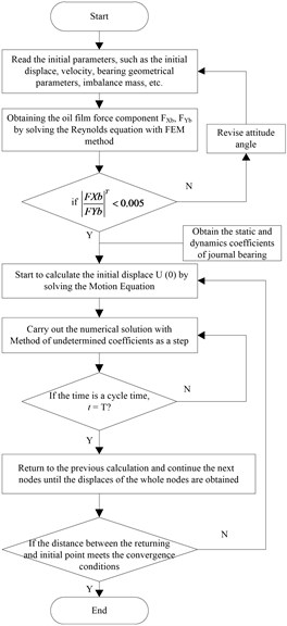
In summary, the whole chart for obtaining the response of the rotor system and solving the dynamic model is shown in Fig. 1.
Fig. 1Chart for solving the unbalance response analysis model
3. Calculation and analysis of the critical speed and the bending unbalance response for the HP-IP rotor
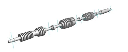
In this paper, the object is the half-speed 1000 MW saturated steam turbine with No. HN1089, and the rotor system are made up of a High Pressure-Intermediate Pressure (HP-IP) rotor, two Low Pressure (LP) rotor and a Generator Rotor. The whole length is 50.9 m. Table 1 shows the basic parameters of the whole rotor system. Fig. 2 shows the 3D model for the rotor of the HN1089.
Table 1Basic parameters of the HN1089
Items | HP-IP | 1# LP | 2# LP | Generator |
Length of the rotor / m | 11.846 | 11.950 | 11.950 | 15.196 |
Density / kg·m-3 | 7855 | 7850 | 7850 | 7850 |
Elastic Modulus / GPa | 204.7 | 206.6 | 206.6 | 206.6 |
Fig. 23D rotor model
The HP-IP rotor is welded by the weld Intermediate-Pressure part and the whole forging High-Pressure part. Each rotor is supported by two three-tile-tilting-pad bearings. For the convenience of adjusting the rotor unbalance, the balancing channel is designed on the two ends of HP-IP rotor, and 24 bolt holes evenly distributes on the both ends of the counterweight, and the angle of each two adjacent holes is 15 degree. For monitoring the bending and vibration of the rotor, the eccentric sensors and vibration sensors are fixed on the unit set. The main critical limit parameters of this rotor are that the value of the bend eccentricity is less than 0.05 m, the vibration limit is 0.25 m under the critical speed, and 0.13 m under the rated speed of 1500 r/min.
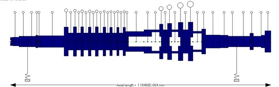
Fig. 3 shows the HP-IP rotor’s 2D model. As shown in Fig. 3, the rotor is modularized to 43 lumped masses and 42 segments for analyzing the dynamic response.
Fig. 32D HP-IP rotor model
3.1. Comparison of the theoretical and test results for the critical speed of the HP-IP rotor
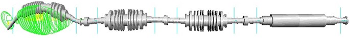
By solving the motion equation with considering the rotor’s gyroscopic effect, the theoretical result of the first order natural frequency of the bearing-HP-IP rotor system is 994 r/min. For comparing the theoretical result, the actual critical speed is tested in the start and stop process, and the result is the range from 967 to 1003 r/min. The relative error between the theoretical and test results is less than 3 %, which shows that the proposed model in this paper has high accuracy. Fig. 4 illustrates the first order vibration mode of the HP-IP rotor system.
Fig. 4First order vibration mode of the HP-IP rotor system
3.2. Performance of the supporting fluid film bearing
The bearing parameters of the HP-IP rotor system are showed in Table 2.
Table 2Bearing parameters
Items | HP-IP rotor | |
Bearing number | Left bearing 1# | Right bearing 2# |
Diameter / mm | 630 | 630 |
Width of supported pad / mm | 560 | 560 |
Corners of supported pad / ° | 107 | 107 |
Width of side pad / mm | 380 | 380 |
Corners of side pad / ° | 43 | 43 |
Width of up pad / mm | 380 | 380 |
Corners of up pad / ° | 53 | 53 |
Inlet oil temperature / °C | 45 | 45 |
Outlet oil temperature/ °C | 52.1 | 54.4 |
In this part, the performance of the tilt pad bearing can be obtained by solving the Reynolds Equation, as shown in reference [10]. The main performance parameters include the oil film pressure distribution, the stiffness and damping coefficients, and film force. The results show from Fig. 5 to 10. In these figures, and mean the main stiffness in the horizontal and vertical direction. and stand for the cross stiffness in the horizontal and vertical direction. and mean the main damping in the horizontal and vertical direction. and stand for the cross damping in the horizontal and vertical direction.
Fig. 5Oil film pressure distribution of bearing 1#
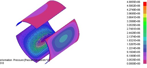
Fig. 6The stiffness coefficients changing with speed of bearing 1#
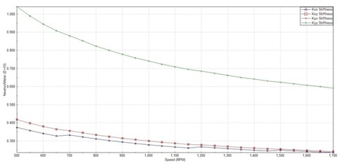
Fig. 7The damping coefficients changing with speed of bearing 1#
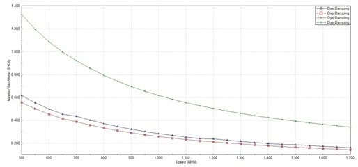
Fig. 8Oil film pressure distribution of bearing 2#
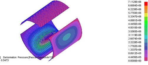
Fig. 9The stiffness coefficients changing with speed of bearing 2#
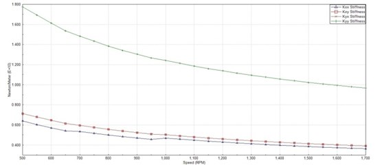
Fig. 10The damping coefficients changing with speed of bearing 2#
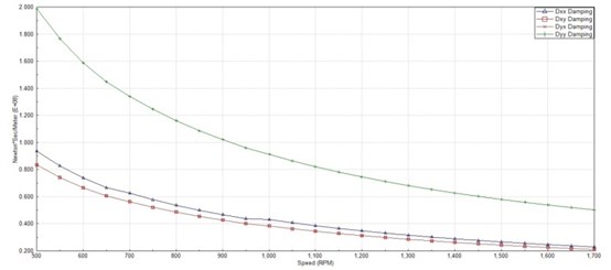
From the above figures, it can be seen that the bearing’s stiffness and damping decrease with the speed under the rated load range, and the degree of decline decrease with increasing of the speed. As shown in figures, in the range of the rated speed (3000 rpm), the slight change of speed only lead to the very slight change of the oil film stiffness and damping. So, under the normal working condition, the performances of the supporting bearing have less influence on the response and stability of the rotor system.
3.3. Results of the unbalance response of the HP-IP rotor with the additional mass
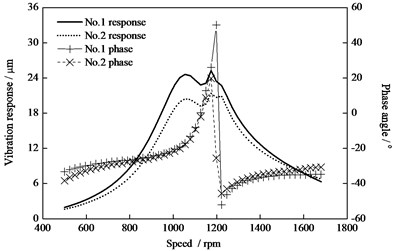
The additional mass in the HP-IP rotor has less influence on the response of other rotors, and mainly focus on itself, so the influence of the additional mass on the other rotor in the units is generally ignored. Due to the fact that the HP-IP rotor is only pass the first-order critical speed zone during the start-up process, so the mode of vibration of the rotor system with the additional mass is close to the first-order mode, and the maximum bending point is located at the middle of the steam seal bridge. Fig. 11 shows the vibration amplitude response (peak-peak value) and phase response under the respective additional mass 1kg at two end 0° position of the HP-IP rotor conditions. In Fig. 11 and the later figures, the peak-peak values at the position of the left and right bearing are respectively noted as No. 1 and No. 2 response. As shown in Fig. 11, the vibration amplitudes in the position of the No. 1 and No. 2 bearing are not consistent due to the different stiffness and damping coefficients of the bearings. So, the two amplitude peak is shown in Fig. 11. The results show that under the above conditions, the first order vibration mode of the unbalance rotor is easy to be induced, and the maximum vibration peak-peak amplitude at the bearing position under the critical speed condition is 0.024 m.
Fig. 11Vibration and phase response of the HP-IP rotor with additional mass 1 kg at rotor ends (0°)
Under the other typical conditions, the vibration amplitude and phase response are shown in Fig. 12 and 13. Fig. 12 shows the vibration amplitude response and phase response under the respective additional mass 1kg at two end 180° position of the HP-IP rotor conditions. Fig. 13 illustrates the response results under the additional mass 2 kg at the first-grade blade of the High-Pressure part.
Fig. 12Vibration and phase response of the HP-IP rotor with additional mass 1 kg at rotor ends (1800)
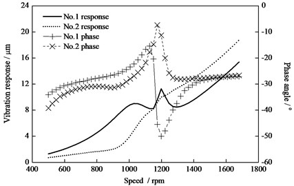
Fig. 13Vibration response under the additional mass 2 kg at the first-grade blade
Compared the above Figs. 11 to 13, the same unbalance mass at the two end of the rotor is easy to induce the first-order vibration mode, and the response value arrive the maximum at the critical speed. Especially, the vibration peak-peak value under the additional mass 1 kg at two ends is near 20 μm. The second order vibration mode is easier to induce only under the opposite direction (180°) additional mass and the vibration value increase with the increase of the speed; especially, the peak-peak value is 10 μm to 20 μm under the additional mass 1 kg at two opposite direction ends and the rated speed 1500 rpm. When the additional mass is located at the middle of the rotor, the peak-peak value at the critical speed is about 43 μm. The unbalance torque in the same plane provided by the additional mass of 2 kg at the middle of rotor and the individual additional mass 1 kg at two ends of rotor is equal, but the vibration response is larger (×2 size) under the middle additional mass conditions, and the middle additional mass is easier to induce the first-order vibration mode.
Comparison between the units (HN1089) and the other thermal power units with the same capacity (1000 MW), the mass and volume of this nuclear half speed units are bigger, but the speed is only half of that; so, the response of this rotor has the low sensitivity to the additional mass.
Meanwhile, by counting the several 1000 MW thermal power’s corresponding data of the additional mass, it is found that the vibration response of the HP-IP rotor under the additional mass at two ends and the same phase is only 1/6 that of the rotor of the thermal power units with the same capacity. So once the HP-IP rotor occurs the bend faults, it is more difficult to adjust by changing the additional mass, or need to add more mass to decrease the vibration response to the qualified level.
3.4. Test results for the bending value of the actual HP-IP rotor
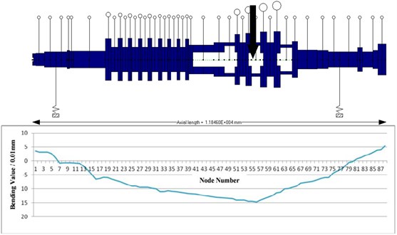
A case on measuring the bending value of the actual HP-IP rotor is finished. The results are shown in Fig. 14. As shown in Fig. 14, the maximum bending value is 0.1465 mm, and the center of the rotor deviate to the Middle Pressure end, as directed by the row. From Fig. 14, it is found that the two bearings have limited the rotor bending, that is, the rotor bend to the same side at the situation between the two bearing, and at the other situation, the bend occur in the opposite side.
Fig. 14HP-IP rotor bending value
3.5. Vibration response of the HP-IP rotor with considering the tested bending value
The above test result of the bending value can be transformed to the unbalance eccentricity, and then the unbalance mass (or force) can be obtained, as noted in Reference [10]. With considering the bending value, the vibration response of the HP-IP rotor is shown in Fig. 15. As shown in Fig. 15, the bending value has great influence on the response results, and the peak-peak values at the position of the left and right bearing (noted as No. 1 and 2) are 456 μm and 397 μm under the critical speed conditions, while the values are 249 μm and 218 μm under the rated speed 1500 rpm. The above value is far beyond the required limits which is 250 μm under the critical speed and 130 μm under the rated speed.
Fig. 15The vibration response with consider the actual bending value
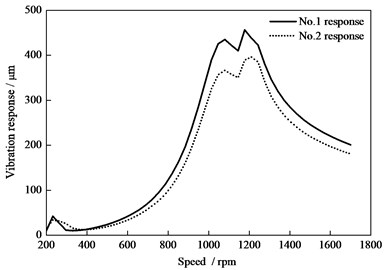
Fig. 16The vibration response with consider the actual bending value under the maximum additional mass conditions
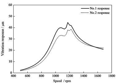
As noted in the beginning of the section 3, the additional mass can be added in 24 bolt holes for balancing the rotor. In the actual field, the maximum additional mass is 3.647 kg and 6.825 kg in two ends of the rotor. With this maximum additional mass, the vibration response of the bending rotor is shown in Fig. 16. As shown in Fig. 16, the peak-peak values at the position of the left and right bearing (noted as No. 1 and 2) are 310 μm and 168 μm under the critical speed conditions, while the values are 195 μm and 93 μm under the rated speed 1500 rpm. The above value is also far beyond the required limits. Hence, it is difficult to decrease the excited response from the bending fault even to add the maximum unbalance mass.
We also calculated that the theoretical maximum additional mass for balancing the bending HP-IP rotor to meet the require limits, are about 28.9 kg and 24.69 kg in the two ends of the rotor. So, it is highly impossible to balance or straighten the bending rotor.
Hence, for straightening the bending rotor, the additional mass method has been proposed in this section, but the feasibility of this method need to be evaluated based on the dynamics model. The purpose of adding additional mass is to ensure that the vibration peak-peak of rotor is low than 0.25 m at the critical speed range, the vibration response is less than 0.13 m at the rated speed, and the the maximum bending value in the gravity center of the rotor is less than 0.06 mm. Once the maximum bending value is more than 0.06 mm, in the actual field, it is necessary to expose the units’ cylinder and to examine the bending degree. If the bending fault is serious, the method that add the additional mass at the middle of the HP-IP rotor is not adopted, and the repairment process from the units manufacturers may be required.
So in this paper, besed on the theoritical results by solving the unbalance response analysis model (the dynamics model), we suggest that only when the bending value with the vibration response under the maximum additional mass on the rotor is far more than 0.06 mm at the critical speed range, the bending fault is seroius and need to be evaluated and deal with this fault by the manufacturers.
4. A case on the HP-IP rotor bending fault evaluation and solution
4.1. Bending fault evaluation based on the unbalance response analysis model
As stated in the above section, when the bending value of the rotor is more than 0.06 mm, it is necessary to expose the units’ cylinder and to examine the bending degree, mean that the method of adding additional mass is not used to deal with the blending fault. So, based on the unbalance response analysis model, the prediction and solution on the bending fault is more easy and accurate than the Eccentric Sensor Measurement Method and the Special Position Measurement Method.
The Eccentric Sensor Measurement Method: The eccentric sensor for measuring the rotor’s unbalance vibration response has been installed in the head part of the HP-IP rotor by the manufacturer, and the critical limit of the unbalance vibration value is 0.05 m. When the value is low than 0.05 m, the unit (rotor system) is perimited to start-up. But in actual, limit to the influence of the different temperature change, gravity effection, etc, the bending phenomenon generally occur at the middle of the rotor. So the data collected by the sensor is not accurate and is not reflect the real bending degree of the gravity center of the rotor. Meanwhile, the existing experimental results also show that even if the value collected by the sensor is low than 0.05 m, it is not clear to obtain the relationship of the bending parameter and the unbalance vibration response from the online measurement. Hence, for the safety purpose, the new bending test or estimation method need be proposed.
The Special Position Measurement Method: Due to the design knowledge of the Nuclear Half-speed Steam Turbine HN1089 that the bending value at the special position of the radial clearance measuring hole located on the body nozzle of the Middle part of the Vapor Labyrinth Seal is equal to the bending value at the gravity center of the rotor, so the displace sensor is located at the nozzle situation by the guiding device. This sensor will collect the clearance data between the interface of the sensor and the HP-IP rotor interface. Therefore, when the rotor run slowly one round, the orbit of the clearance is obtained, and the actual maximum bending value is calculated by measuring the maximum distance in the diagonal line direction of the orbit. In the actual field, when this value is more than 0.06 mm, the bending fault is not solved by add the additional mass and it is necessary to expose the units’ cylinder, even to repair in the manufacturer. Only when the value is lower than 0.06 mm, the unbalancing mass method can be adopted. Based on the unbalance response analysis model, the full dynamic balancing process will be finished. With this method to solve the bending fault, 12 working days will be saved, means that millions of Yuan will be saved for the power plant.
4.2. Bending fault solution
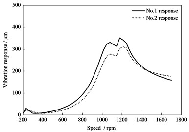
A case in 2014, due to the improper operation, the rub and impact at the bridge steam seal situation of the HP-IP rotor occur, and the vibration response of the rotor continues to increase up to 0.18 m, which is beyond the limit (0.13 m) at the rated speed. So the power of units is decreased and then the units is closed. The bending value is about 0.2 m. After 3 hours repaired, the bending value decrease to 0.007-0.008 m, which is meet to the requirement of the start-up process for the units. So, the units is started, the vibration response (vibration peak-peak value in the horizontal direction) at the position of the two bearings (noted the left bearing is No. 1 and the right bearing is No. 2) with the speed increasing is shown as Fig. 17.
Fig. 17The vibration response of the HP-IP rotor after repair
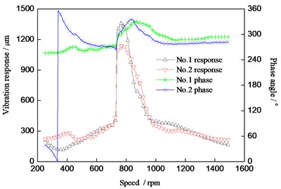
Fig. 18The vibration response of the HP-IP rotor for the bending test
As shown in Fig. 17, in the start-up process, the phase of No. 1 is consistent with that of No. 2, and the absolute error is lower than 30 degrees. So, the bending fault mode is the first order bending deformation of the HP-IP rotor.
Meantime, the bending value test with the Special Position Measurement Method is 0.15 mm, which is beyond the limit (0.06 mm) of strengthening the rotor by the additional mass method stated in the section 4.1. So, the additional mass method is not applied to solve this bending fault.
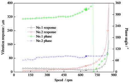
For further verifying if the forever bending emerges in the HP-IP rotor, the method by adding the additional mass in two end of the rotor is proposed, and the running operation for obtaining the test data is carried out. The eight screws are added in the channel of the left end of the rotor, the total additional mass is 2.66 kg, while the five screws are added in the channel of the right end of the rotor and the total additional mass is 2.998 kg. When the run speed is up to 855 rpm, the vibration (peak-peak value in the horizontal direction) in the position of the left and right bearings is beyond the limit value (0.25 m), and the maximum vibration response is more than 0.3 m, as shown in Fig. 18.
As the stated in the Section 3.1, the speed 855 rpm is nearly the range of the critical speed. From Fig. 18, when the speed is close to the critical speed, the vibration response increases quickly; which means that the bending degree is heavy, and the unbalance is serious. The additional mass method in the actual field is not adopted in completely dealing with this serious bending fault. Meanwhile, comparison Fig. 17 and 18, the phase with and without the additional mass has little change, which means that it is great possibility that the forever bending emerged in the HP-IP rotor.
By summarized the above theoretical and test results, it is decided that the HP-IP rotor need to be sent to manufacturer for maintenance procedure. In the factories of the manufacturers, the bending value collected by the radial run-out detector is finished, and the result show that the maximum bending value appear in the bridge steam seal of the HP-IP rotor part and the No. 1, 2 of the IP part. The maximum value is 0.15 mm, and the bending value decrease along the axial direction of the rotor to the rotor ends. The results are consistent with that of the Special Position Measurement Method in the section 4.2. Furthermore, the wear appears in the position of the Bridge Steam Seal and the worn thickness is 1.5 mm. The serious wear is derived from the rotor bending. This bending fault leads to the plastic deformation of the rotor, and the distribution of the unbalance mass which cause the over-limit vibration response. Meanwhile, it is found that the hardness in the bottom zone of the wear parts is lower than the normal hardness of the rotor, which can be induced that the temperature from the wear fault is higher than the final tempering temperature of the rotor material.
For strengthening the bending rotor, the comprehensive method is proposed, which is the stress remove in the partial zone plus the turning procure. Firstly, the stress of the wear zone is removed. After the stress in the partial zone is removed, the maximum bending value collected again by the radial run-out detector is turned. Then, for straightening the rotor, the essential step of the heat preservation is performed. Finish, the dynamic balance for the straightening rotor is carried out. Meanwhile, based on the model proposed in this paper, the vibration response for the repaired HP-IP rotor is solved. The theoretical results show that both of the peak-peak values (in the horizontal direction) at the left and right bearing position under the rated speed (1500 rpm) condition are 0.004 m, which is far lower than the limit range (0.032 m) specified in the related documents.
When the repaired HP-IP rotor was installed in the power plant, some typical data in the start-up process are also collected. The test results show that the maximum vibration response in the critical speed range is 0.075 m, which is far lower than the shut-down limit range (0.25 m). Under the rated speed (1500 rpm), the maximum vibration response (the peak-peak values in the horizontal direction) is 0.033 m, which is lower than the alert limit (0.06 m) specified in the related documents.
5. Conclusions
1) The unbalance response dynamics model for the Nuclear Half-speed 1000 MW Saturated Steam Turbine with No. Dongfang HN1089 is constructed for solving the bending problem of the HHP-IP rotor system and the model is a general dynamics model coupled the unbalance mass-Bearings-Rotor elements.
2) According to the proposed model, the unbalance response of the Turbine HN1089 is obtained and the additional mass method is limit to straighten the bending rotor. The results show that the vibration response of the HP-IP rotor under the additional mass at two ends and the same phase is only 1/6 that of the rotor of the thermal power units with the same capacity (1000 MW).
3) Based on the proposed model, the results show that the unbalance torque in the same plane provided by the additional mass of 2 kg at the middle of rotor and the individual additional mass 1kg at two ends of rotor is equal, but the vibration response is larger (×2 size) under the middle additional mass conditions, and the middle additional mass is easier to induce the first-order vibration mode. Comparison between the units (HN1089) and the other 1000 MW Thermal Power units with the same capacity, the response of this rotor in the units (HN1089) has the low sensitivity to the additional mass.
4) For strengthening the bending rotor, the comprehensive method is proposed, which is the stress remove in the partial zone plus the turning procure. The test results show that the maximum vibration response of the repaired HP-IP rotor in the critical speed range is 0.075 m, which is far lower than the shut-down limit range (0.25 m). Under the rated speed (1500 rpm), the maximum vibration response (the peak-peak values in the horizontal direction) is 0.033 m. So, based on the dynamic model, the bending fault evaluation and solution for the special units is to be verified, which is great guidance value to solve the similar engineering problems.
References
-
He Y. L., Ke M. Q., Wang F. L., Tang G. J., Wan S. T. Effect of static eccentricity and stator inter-turn short circuit composite fault on rotor vibration characteristics of generator. Transactions of the Canadian Society for Mechanical Engineering, Vol. 39, Issue 4, 2015, p. 767-781.
-
Wan S. T., He Y. L., Zhan, C. G. Effect of internal power-angle on turbo-generator rotor vibration characteristics under eccentricity faults. Transactions of the Canadian Society for Mechanical Engineering, Vol. 38, Issue 1, 2014, p. 63-79.
-
Donat M., Dusek D. Eccentrically mounted rotor pack and its influence on the vibration and noise of an asynchronous generator. Journal of Sound and Vibration, Vol. 344, Issue 1, 2015, p. 503-516.
-
Chandra N. H., Sekhar A. S. Fault detection in rotor bearing systems using time frequency techniques. Mechanical Systems and Signal Processing, Vol. 72, Issue 73, 2016, p. 105-133.
-
Ren Z., Zhou S., Li C., Wen B. Dynamic characteristics of multi-degrees of freedom system rotor-bearing system with coupling faults of rub-impact and crack. Chinese Journal of Mechanical Engineering (English Edition), Vol. 27, Issue 4, 2014, p. 785-792.
-
Jalali M. H., Ghayour M., Ziaei Rad S., Shahriari B. Dynamic analysis of a high speed rotor-bearing system. Measurement: Journal of the International Measurement Confederation, Vol. 53, Issue 1, 2014, p. 1-9.
-
Rosyid A., Elmadany M., Alata M. Optimal control of reduced-order finite element models of rotor-bearing-support systems. Journal of the Brazilian Society of Mechanical Sciences and Engineering, Vol. 37, Issue 5, 2015, p. 1485-1497.
-
Brouwer M. D., Sadeghi F., Ashtekar A., Archer J., Lancaster C. Combined explicit finite and discrete element methods for rotor bearing dynamic modeling. Tribology Transactions, Vol. 58, Issue 2, 2015, p. 300-315.
-
Da Fonseca E Albuquerque R. B., Barbosa D. L. Evaluation of bending critical speeds of hydrogenerator shaft lines using the transfer matrix method. Proceedings of the Institution of Mechanical Engineers, Part C: Journal of Mechanical Engineering Science, Vol. 227, Issue 9, 2013, p. 2010-2022.
-
Zhang G. Y., Tian Y. N., Huang H. Z., Zhou M. Nonlinear response of the generator rotor under the unbalanced electromagnetic force. Journal of Vibroengineering, Vol. 16, Issue 6, 2014, p. 2983-2997.
-
Xu X. P., Han Q. K., Chu F. L. Nonlinear vibration of a generator rotor with unbalanced magnetic pull considering both dynamic and static eccentricities. Archive of Applied Mechanics, Vol. 86, Issue 8, 2016, p. 1521-1536.
-
Zhang X., Han Q., Peng Z., Chu F. A new nonlinear dynamic model of the rotor-bearing system considering preload and varying contact angle of the bearing. Communications in Nonlinear Science and Numerical Simulation, Vol. 22, Issues 1-3, 2015, p. 821-841.
-
Zhang L., Ma Z., Wu Q., Wang X. Vibration analysis of coupled bending-torsional rotor-bearing system for hydraulic generating set with rub-impact under electromagnetic excitation. Archive of Applied Mechanics, Vol. 86, Issue 9, 2016, p. 1665-1679.
-
Yu M., Feng N., Hahn E. J. An equation decoupling approach to identify the equivalent foundation in rotating machinery using modal parameters. Journal of Sound and Vibration, Vol. 365, 2016, p. 182-198.
-
Hu A., Hou L., Xiang L. Dynamic simulation and experimental study of an asymmetric double-disk rotor-bearing system with rub-impact and oil-film instability. Nonlinear Dynamics, Vol. 84, Issue 2, 2016, p. 641-659.
About this article

This work was supported by National Natural Science Foundation of China (Project No. 51575418).
