Abstract
The article presents the methodology of body vibration analysis of an inspection robot with the use of flexible connection between the body and the track propulsion modules. The article presents the methodology of selection of motion parameters of an inspection robot, taking into account the vibration of the robot body. The speed of movement of the robot affects the frequency of contact track claws with the ground, which is related to the frequency of vibration excitation. Robot motion parameters are chosen in such a way so as not to over-stimulate the natural frequency of the system. Due to the vibration reduction, it was possible to install a visual system based on an Ethernet video camera without a stabilizer in the body of the robot. Such an approach enables mass production of robots without active suppression systems and video stabilizers which generate high production costs, increase weight of robots and energy consumption.
1. Introduction
Design and production of mobile tracked robots and their working parameters analysis has been the subject of many publications [1-6] and research conducted in many companies. The robots built today replace people during dangerous tasks or they are used in places where people cannot work. Robots are used in places with limited access which need inspection of the conditions there. The development of inspection robotics results in the increased use of such solutions in the military and emergency services.
The key feature of such robots are vision systems which enable inspection of unknown environments [5, 7-13]. Vibration reduction and robot’s video cameras with image stabilization feature are crucial to provide the operator with high quality vision.
The article [1] describes a robot with so called active flippers, which increase the grip on uneven surfaces. Operating them manually is difficult, especially when the video camera vision is limited. The authors of the article have designed an autonomous system based on an independent driver which uses a 3-dimensional terrain scanner to collect information.
In the article [2] the authors focus on vibrations, noises and impacts which play an important role in mechanical systems, especially in transport technology. They reduce the effectiveness, safety and comfort of the transport process. Flow-induced vibrations may cause a malfunction of fragile devices and people’s discomfort or they may result in damaging buildings and infrastructure. In diagnostic systems, vibration signals can be used as a source of information on the condition of propulsion system. Modal analysis of the vehicle body is crucial for the safety, comfort and stability of driving.
In the article [5] the authors describe a new image stabilization system which provides easier control of emergency robots. As the orientation of robots changes quickly when they move around debris, image stabilization is necessary to let the operators focus on finding the victims. The authors carried out experiments to test the video camera system and the results confirmed its efficacy. In the article [7] the authors present an advanced mobile robot image stabilization system which uses an extended Kalman filter. Camera vibrations caused by uneven surfaces, stairs or muddy terrain lower the quality of vision. The measurement of the robot’s video camera vibration phase was used to actively compensate for the vibration. The results showed the efficacy of the solution. In the article [11] the authors describe the measurement of the video camera vibration taken with the use of a gyroscope sensor and advanced analysis affecting the quality of the image. In the article [12] the problem of an increasing number of pixels in modern camera matrices and their vulnerability to vibration induced blurring was described. Also, the methodology of tri-axis video camera vibration measurement with result assessment and image stabilization was presented. Dynamical system vibration reduction has been the subject of many research projects [14-16].
The article will present the analysis of the vibration of inspection crawler robot visual system. The conclusion after analyzing the literature on the subject is as follows: at the stage of the design of devices with vision systems, proper suspension systems are not used to achieve passive vibration reduction, nor are the optimum parameters of movement looked for. Instead, additional active vibration reduction or video camera stabilization systems are installed in the robots. The systems are expensive, increase the weight of robots and their energy consumption.
The module robot [17, 18] Fig. 1 is able to monitor and analyse the technical condition of flat surfaces, ventilation ducts and pipes, both “dry” and filled with liquids. The usefulness of the robot was confirmed by the good results of the tests carried out in Kraków Waterworks.
Fig. 1Crawler inspection robot
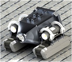
a) CAD model
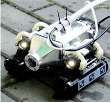
b) Picture of the prototype
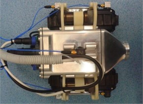
Fig. 2Robot’s vision system
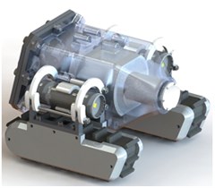
a) CAD model of the camera location in the body of the robot
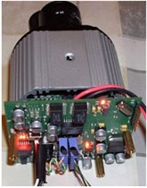
b) Picture of the camera and its control electronics
The vision system used in the robot (Fig. 2) is based on an Ethernet video camera AV2100. It is a 2 megapixel colour camera with 1600×1200 maximum resolution. The video camera is the base sensor system of the robot and it provides the operator with high quality vision.
The video camera does not have an image stabilization system. Strong vibration prevents the operator of the robot from seeing the image. That is why the analysis of the robot’s vibrations was necessary. The movement parameters of the robot also had to be designed to meet the desired conditions.
The aim of the research presented in this article was to verify how the track suspension works, to assess vibration isolation features and to find parameters of motion, which do not cause unacceptable vibrations of the robot’s body. The research was done on the test rig with the use of a vibration inductor to simulate the robot’s contact with the ground during movement. Next, traction analysis was carried out and the robot’s vibration during field tests was measured.
2. The analysis of the robot motion
Two track modules were used as a propulsion system in the robot [17-20]. Continuous track is a mechanism that enables vehicles to operate in rough terrain. Vehicles with the mechanism are able to negotiate difficult terrain obstacles and they are less likely to get stuck or skid. Tracks extend the contact area between the vehicle and the ground and let the vehicle go up slopes with a steep gradient.
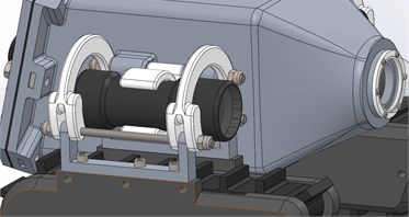
The amount of vibration of the robot’s body and the video camera depends on the suspension Fig. 3 which connects the body and tracks. The suspension was designed to achieve the maximum reduction of the vibration transmission from the tracks to the body.
Fig. 3CAD model of the track suspension
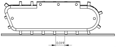
One of the features of tracked robots, as opposed to wheeled robots, swimming robots and flying robots, is relatively low movement fluency. The reason for that are sudden jerks and skids that happen when a claw gets into the ground and then leaves it [17], which in turn causes strong vibrations of the robot’s body. Another factor influencing the dynamics of tracked robots is the changing number of claws being in contact with the ground Fig. 4, which changes the stiffness of the construction in time.
Fig. 4Track claws consecutively getting in contact with the ground
The aforementioned jerks activate the resonant frequencies of the system and therefore it is expected that in real-life situation, during robot’s movement, the track-to-body vibration transmission rate will be much higher than 1.
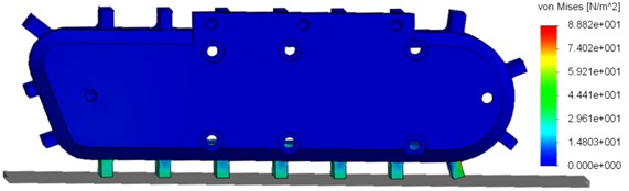
The pressure of the claw on the ground (average 4.2 N) and the tension caused by the contact with the ground Fig. 5 were assessed according to the numerical analysis of the model’s movement with the use of FEM. The reduced tensions presented in Fig. 5 are also called Huber’s tensions or Huber-Mises’ tensions. The presentation is very often used to show the objective indicator of material stress in the state of multi-axis tension, i.e. if the material is not exposed to simple bending or stretching.
FEM simulation was done in the simulation module of SolidWorks software. Chosen fixing and weight were in accordance with the project of the robot. The results of the analysis were the pressure forces of the claw on the ground, the graphic presentation of the normal tensions according to Mises and dislocation of claws.
Fig. 5Tension in the claws of the robot during movement
The robot’s track propulsion modules are equipped with direct-current motors with permanent magnets and with planetary gears with 1:71 reduction ratio. It results in the fact that for the maximum PWM generated by the motor’s controller the speed is 0.15 m/s and this is the maximum possible speed of the robot. The influence of the robot’s speed on the natural frequencies stimulation is as follows. Crawler robot vibration during movement is caused mainly by the interaction between the claw and the ground [17]. The frequency of the interaction depends on the speed of the robot. The speed is between 0-0.15 m/s. The distance between the claws is 0.019 m. Thus, the relation between the speed of the robot and the frequency of the claw’s contact with the ground is: . Therefore, the range of the claw-to-ground interaction force frequency is approximately 0-7.9 Hz. The information on the amplitude and frequency was used in dynamics research, during which the influence of the force caused by the claw hitting the ground on the body vibration and quality of the image from the video camera in the robot’s body were analyzed.
3. Dynamical test on the test rig
The first stage of the experimental research was to determine the natural frequency of the robot. For this purpose the robot was excited in quasi-unbounded conditions by means of pulse excitation and the robot’s oscillations were measured with an accelerometer. According to the theory of mechanical oscillations the pulse excitation induces the oscillations with the natural frequency of the system. For that reason, the acceleration signal underwent the analysis in frequency domain with the application of Fourier transformation. Fig. 6 shows the acceleration signal spectrum.
Fig. 6Acceleration signal spectrum
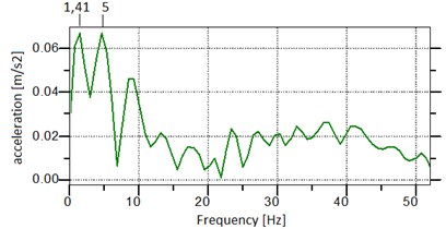
It is known that any real-world system has many natural frequencies, however some of them are more important than others in the sense that the oscillations occurring with given natural frequencies are bigger than in the other resonance zones. In case of the tested robot two natural frequencies are important, that is 1.41 Hz, and 5 Hz, where the oscillation amplitudes are the largest. In this way, the resonance frequencies of the system were determined, that is the natural frequencies.
Next, the analysis of the robot’s oscillation was conducted on a testbed, which aimed to investigate the performance of the system with the input induced by the track claws coming into contact with the surface. The robot was placed on a stable surface and a force generated by a Mini SmartShaker K2007E01 vibration inductor was put to the claw on one of the tracks. The parameters of the force were measured with the use of a 6082-D PCB Piezotronic impedance head. The amplitude of the force was about 4.2 N and the frequency of the force was changed in the range of 0.01-7.9 Hz.
Moreover, on the track and the body, tri-axis acceleration sensors were installed to assess the vibration of these elements. During the analysis of the vibration of the system, vibroisolation rate for tri-axis vibration state was used. The vibroisolation rate was expressed as the body displacement effective value to the track displacement effective value:
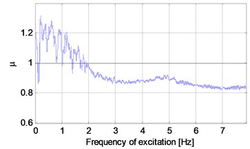
where , , are RMS of the components of the body displacement , , assessed in relation to the axis of the reference system of the sensor on the robot’s body, , , are RMS of the components of the track displacement , , assessed in relation to the axis of the reference system of the sensor on the robot’s track. The effective values of the displacement were calculated with the use of the RMS function in time window 1 s. The use of the RMS values of displacements decreases the influence of “peaks” of the temporary vibration values, so the rate is more stable and easier to analyse. The vibroisolation rate is presented in Fig. 7. The conclusion is that for the low force frequencies, the rate , i.e. body vibration is higher than track vibration. It is related to the fact that the first resonance zone is in the frequency range of 1.3-1.9 Hz and it is connected with the first natural frequency of the robot 1.41 Hz, which was determined experimentally. It is well known that in the resonance zones related to low frequencies, in case of low suppression, displacements may be relatively high. At the next stage of the experiment, for the force frequency higher than 2 Hz, the rate . The next increase of the rate can be noticed with the frequency 5 Hz, which is connected with the second natural frequency stimulation.
Fig. 7The robot’s body vibroisolation rate
4. Analysis of robot traction
Traction analysis based on an experimental study was the next step. It was carried out in the possibly most difficult conditions in terms of vibration, i.e. on hard and adhesive surface. In such conditions track vibration caused by the claws hitting the ground is the highest because of the low suppression of the surface. A series of eight experiments was conducted in which the robot moved straight at the constant speed in the range of 0.05-0.15 m/s. The speed range corresponds to the frequencies beyond the first zone of resonance. The speeds of the robot and the related force frequencies caused by the claws coming into contact with the ground are presented in Table 1. Due to the limitations of the robot’s purpose-built control software in terms of the choice of speed, eight chosen speeds of the motion of the robot were utilised in the tests. Choosing intermediate speeds would require modifying the control software. The vibrations were measured with the use of five tri-axis acceleration sensors located as follows: one sensor was installed on the body of the robot and the rest of them, in pairs, were installed on the track propulsion modules Fig. 8.
During the system vibration analysis, spectral analysis and the vibroisolation rate were used once again. The was defined as follows:
where , , are RMS of the components of the body displacement , , assessed in relation to the axis of the reference system of the sensor on the robot’s body, , , are RMS of the components of the track displacement , , assessed as the average displacement of the four sensors in the given directions:
where , , are the components of the track displacement assessed in relation to the axis of the reference system of the sensor on the robot’s body. Because of the fact that the speed of the robot during traction analysis had constant values (see: Table 1), the force frequency was also constant. Thus, the vibroisolation rate fluctuated around the same value during each experiment. The values of for given speed values are presented in Table 1 and Fig. 10(a). It turns out that in every case . The main factor influencing value is the vibration related to the robot’s movement, i.e. longitudal oscillation. The oscillation of the body is caused by shaking tracks but tracks vibration itself is lower because of the highly adhesive surface.
Fig. 8The location of the acceleration sensors on the robot during traction analysis
On the basis of the measured acceleration, the velocity of the body vibration was determined, and then a Fourier transform was performed in order to represent the signal in the frequency domain. To improve the quality of frequency analysis FlatTop window was used, and to transform the FFT function with the length of 29 was applied. ZoomFFT option was used, which allows for more accurate calculation in the selected low frequency range. The results are shown in Fig. 9, which contains amplitude-frequency characteristics of the vibration velocity of the body in the , and directions. Due to the large number of charts, the characteristics for successive movement speeds have been grouped together and can be distinguished on the basis of the colour shown in the chart legend.
The frequency and amplitude of the main components of vibration velocity signals depend on the speed of the robot. The analysis of the charts shows that most of the vibration energy is concentrated at the frequencies of up to 20 Hz for vibrations in the direction. The vibration in the other directions is several times smaller. To quantitatively evaluate the vibration in each direction in the band of 0-20 Hz, features in the frequency domain were defined:
Fig. 9Amplitude-frequency characteristics of the vibration velocity of the robot’s body
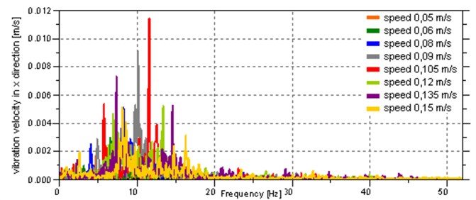
a) In the direction
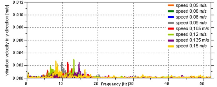
b) In the direction
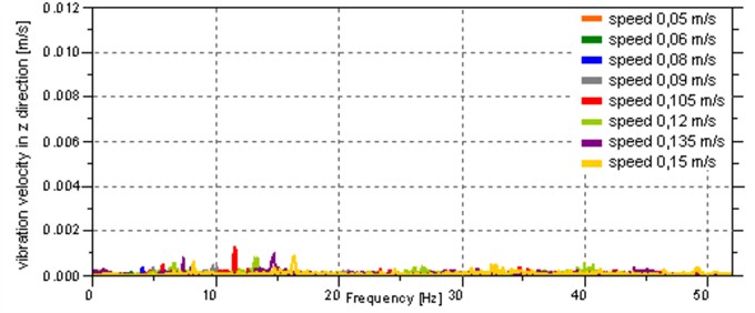
c) In the direction
These are the maximum and root mean square in the band of 0-20 Hz, where , , are vibration velocity of the body in , and directions represented in the frequency domain. The values of these features, for each speed, are presented in the Table 1. and shown in Fig. 10(b) and Fig. 10(c).
From the analysis of the data presented in the Table 1 and Fig. 10 it follows that the greatest vibration occurs for the speeds of 0.09 m/s and 0.105 m/s, which cause the stimulation of the second natural frequency of the system.
Fig. 10Graphical presentation of the values of vibration parameters for given motion speed values
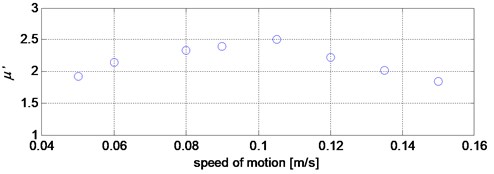
a) Vibroisolation rate
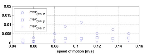
b) Maximum in spectrum of velocity in the band 0-20 Hz
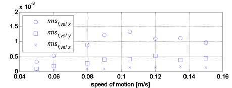
c) Root mean square of spectrum of velocity in the band 0-20 Hz
Table 1The values of vibration parameters for given movement speed values
Experiment No. | 1 | 2 | 3 | 4 | 5 | 6 | 7 | 8 |
Robot’s speed, m/s | 0.05 | 0.06 | 0.08 | 0.09 | 0.105 | 0.12 | 0.135 | 0.15 |
Frequency, Hz | 2.362 | 3.158 | 4.210 | 4.737 | 5.526 | 6.316 | 7.105 | 7.895 |
1.9210 | 2.1364 | 2.3298 | 2.3981 | 2.4977 | 2.2194 | 2.0116 | 1.8398 | |
0.0017 | 0.0030 | 0.0051 | 0.0091 | 0.0114 | 0.0052 | 0.0073 | 0.0051 | |
0.0005 | 0.0007 | 0.0012 | 0.0025 | 0.0025 | 0.0029 | 0.0024 | 0.0027 | |
0.0001 | 0.0003 | 0.0004 | 0.0004 | 0.0012 | 0.0008 | 0.0009 | 0.0009 | |
0.0003 | 0.0005 | 0.0009 | 0.0012 | 0.0013 | 0.0011 | 0.0011 | 0.0010 | |
0.0001 | 0.0002 | 0.0003 | 0.0004 | 0.0004 | 0.0005 | 0.0004 | 0.0004 | |
0.0000 | 0.0000 | 0.0001 | 0.0001 | 0.0001 | 0.0001 | 0.0002 | 0.0001 |
5. Conclusions
The article presented the verification research of the crawler inspection robot, which focused on the influence of the robot motion on the vibration of the robot’s body with a camera. The robot can move at any speed with a range of 0.05-0.15 m/s without affecting the safety of the system. However, it has an impact on the quality of the image from the camera. Therefore, in the inspection mode the crawler robot cannot move with the 0.09-0.105 m/s speed range. The suspension vibroisolation rate was also assessed and it oscillates, in real-life conditions, between 1.8398 and 2.4977, as it depends on the speed of the robot’s movement.
References
-
Okada Y., Nagatani K., Yoshida K., Yoshida T., Koyanagi E. Shared autonomy system for tracked vehicles to traverse rough terrain based on continuous three-dimensional terrain scanning. IEEE/RSJ International Conference on Intelligent Robots and Systems, 2010, p. 357-362.
-
Ragulskis M., Munoz L., Burdzik R., Real J. I., Hsieh W. H., Zimroz R. Shock and vibration in transportation engineering. Shock and Vibration, Vol. 2016, 2016.
-
Tutak J. S., Wiech J. Horizontal automated storage and retrieval system. Advances in Science and Technology – Research Journal, Vol. 11, Issue 1, 2017, p. 82-95.
-
Ahmed M., Eich M., Bernhard F. Design and control of MIRA: a lightweight climbing robot for ship inspection. International Letters of Chemistry, Physics and Astronomy, 2015, p. 55-128.
-
Hayashi K., Yokokohji Y., Yoshikawa T. Tele-existence vision system with image stabilization for rescue robots. Proceedings of the IEEE International Conference on Robotics and Automation, 2005, p. 50-55.
-
Tao W. M., Zhang M. J., Ma O. Modeling and vibration suppression for industrial track robots. Proceedings of IEEE International Conference on Robotics and Automation, 2006, p. 1072-1077.
-
Choi Y. W., Kang T. H., Lee S. G. Development of image stabilization system using extended Kalman filter for a mobile robot. International Conference in Swarm Intelligence, Springer Berlin Heidelberg, 2010, p. 675-682.
-
Günthner W. Enhancing cognitive assistance systems with inertial measurement units. Studies in Computational Intelligence, Vol. 105, 2008, p. 79-99.
-
Kasturin A. Planning trajectory of the mobile robot with a camera. Annals of DAAAM and Proceedings, Vol. 26, Issue 1, 2015, p. 407-416.
-
Suzuki S., Hasegawa S., Okugawa M. Remote control system of disaster response robot with passive sub-crawlers considering falling down avoidance. Robomech Journal, 2014, http://doi.org/10.1186/s40648-014-0020-9.
-
Hayashi K., Tanaka M., Kusaka H., Hashi H. New approach on multi-axial analysis of camera shake. Digest of Technical Papers International Conference on Consumer Electronics, 2010.
-
Nishi K., Ogino R. 3D camera-shake measurement and analysis. IEEE International Conference on Multimedia and Expo, 2007, p. 1271-1274.
-
Kawabata K., Sato H., Suzuki T., Tobe Y. A wireless camera node with passive self-righting mechanism for capturing surrounding view. Vision Sensors and Edge Detection, 2010, https://doi.org/10.5772/10133.
-
Żabiński T., Mączka T., Kluska J., Kusy M., Gierlak P., Hanus R., Prucnal S., Sęp J. CNC Milling Tool Head Imbalance Prediction Using Computational Intelligence Methods. Lecture Notes in Artificial Intelligence LNAI 9119, Part I, 2015, p. 503-514.
-
Gierlak P., Burghardt A., Szybicki D., Szuster M., Muszyńska M. On-line manipulator tool condition monitoring based on vibration analysis. Mechanical Systems and Signal Processing, Vol. 89, 2017, p. 14-26.
-
Ragulskis K., Palevicius R., Ragulskis M., Rubliauskas D., Palevicius A. Analytical, numerical, and experimental investigation of self resonance in vibration excitation systems. Smart Structures and Materials, International Society for Optics and Photonics, 2005, p. 641-649.
-
Kohut P., Kurc K., Szybicki D., Cioch W., Burdzik R. Vision based motion analysis and deflection measurement of a robot's crawler unit. Journal of Vibroengineering, Vol. 17, Issue 8, 2015, p. 4112-4121.
-
Kurc K., Szybicki D. Determination of dynamic parameters for underwater robots with crawler drives. Applied Mechanics and Materials, Vol. 817, 2016, p. 130-139.
-
Ciszewski M., Buratowski T., Giergiel M., Małka P., Kurc K. Virtual prototyping, design and analysis of an in-pipe inspection mobile robot. Journal of Theoretical and Applied Mechanics, Vol. 52, Issue 2, 2014, p. 417-429.
-
Ciszewski M., Buratowski T., Uhl T., Giergiel M., Małka P. Modeling and testing of a tracked mobile robot for inspection and cleaning of water storage tanks. Journal of Civil Engineering, Environment and Architecture, Vol. 62, Issue 32, 2015, p. 61-74.
Cited by
About this article

