Abstract
To study the aerodynamic noise characteristics of alternators in vehicles, this paper established a computational model for the aerodynamic noise of an alternator based on computational fluid dynamics (CFD). The alternator adopted a non-scaling model and considered the detailed structure of collectors and other parts. Based on Lighthill acoustic theory, this paper adopted three-dimensional and large eddy simulation (LES) to conduct an unsteady numerical simulation for the flow field around the alternator, and Ffowcs Williams-Hawkings (FW-H) model was then adopted to conduct an unsteady computation for the aerodynamic noise of the alternator in the far field. When the rotational speed of the alternator was 10000 r/min, this paper obtained the aerodynamic noise characteristics of the alternator and the unsteady flow field structure around the alternator. Studied results showed: The main aerodynamic noise sources of the alternator were front fan, rear fan and stator structure; main influence orders of aerodynamic noises were the 6th, 8th, 10th, 12th, 18th, 24th, 30th and 36th orders. Similarly, this paper also conducted an experimental test on the noise of vehicle alternators. The main influence orders of aerodynamic noises of alternators were the 6th, 8th, 10th, 12th, 18th, 24th, 30th and 36th orders, which was consistent with the working condition of numerical simulation. It showed the correctness of computational results in this paper. In addition, this paper adopted the method of vector synthesis and the distribution of fan blades of the alternator to explain the cause of various orders and provided engineering application foundation for further reducing the noise of main orders.
1. Introduction
With the rapid development of economy and the improvement of people’s living standards, the comfort of vehicles has become more and more demanding while the number of vehicles has increased rapidly in recent years. Researches on NVH of vehicles have expanded from vehicles to parts. As one of key parts of vehicles, the alternator has a great impact on the noise of vehicle assembly, especially single orders [1]. At the section of high rotational speed more than 6000 r/min, aerodynamic noises become a main part of alternator noises and are the most difficult to control [2-4]. Noise control becomes difficult due to the complexity of aerodynamic noise sources and the inseparable noise sources of alternators and uncertain contribution amount of main orders to total noise, which has a direct influence on the improvement of performance and noise characteristics of alternators.
To address the aerodynamic noise problem of alternators, a number of scholars applied theoretical analysis, experimental research, numerical simulation and other methods to conduct many studies on the aerodynamic noise of alternators to reduce the total noise of alternators and improve the fan’s flow rate, and summarized the rule of optimizing the structural parameters of front and rear end caps and fan blades of alternators. In terms of theories, Lighthill acoustic analogy theory had a serious influence [5, 6] and has been applied to predict and reduce the aerodynamic noise of alternators. In the aspect of experimental research, people conducted a lot of experiments in order to learn about the characteristics, generation mechanism, noise source, noise transmission way of alternators [1, 3, 4, 7, 8], pointed out that fluctuation pressure caused by the high-speed rotation of front and rear fan blades of alternator was aerodynamic noise source, and proposed some measures to reduce the noise of the alternator. Fiedler [9] identified the main noise source of switch reluctance machine through experiments, pointed out that aerodynamic noises caused by the slotting of rotor were an important noise source of switch reluctance machine, and proposed corresponding noise reduction methods. Zhang [10] used microphone array to identify the noise source of driving system of electric vehicle motors in the case of steady-state work and pointed out that noises in the low-frequency were mainly from cooling fan, noises in the mid-frequency were mainly from gearbox, and fan and gearbox were main noise sources in the high frequency. Wang [11] identified main noise sources through analyzing the frequency spectrum of vibration signal of motors. Li [12] adopted the method of selecting operation to test the noise of vehicle sunroof and its system, pointed out that the noise of sunroof motor was the main noise source of sunroof system, and analyzed the noise spectrum of sunroof motor. Andrea [13] tested and analyzed the noise of small brushless direct-current motor and pointed out that cogging torque was the main noise source of motor. In the aspect of alternators, there are few related studies at present. Zhang [14] studied the aerodynamic noise of vehicle claw-pole alternator through experiments. However, he only analyzed the noise of cooling fan and failed to analyze the aerodynamic noise of rotor rotation and stator slotting. Fu [15] experimentally studied the electromagnetic noise of claw-pole alternators and pointed out that there was mainly electromagnetic noise at the stage of low speed. However, he failed to accurately analyze the generation mechanism of electromagnetic noises. In the aspect of numerical simulation research, Neise pointed out that dipole point source could be used to describe the aerodynamic noise caused by the high-speed rotation of centrifugal cooling fan [16, 17]. Based on the research of Neise, W. Kim [18] adopted commercial CFD software and acoustic software Flow Noise S/W to maximize fan flow and minimize sound pressure levels of noises based on the optimum design of Taguchi method and obtained the optimized rear fan blades of alternators through optimizing the design parameters of rear fan blades of alternators. However, standard - model was used as the prediction model of aerodynamic noises. The impact of vortex noises on total noise was ignored. In the case of high rotational speed (18000 r/min), numerical simulation results were about 12dBA more than experimental test results. When total noise decreased, the noise amplitude of main orders increased. Wang [19] adopted the method of vector synthesis to optimize the front fan blades of vehicle alternators and obtained noise reduction characteristics including obvious noise reduction effect in the 12th and 18th orders and little noise reduction effect in other orders.
In conclusion, experimental methods were used to study the fan noise of vehicle alternators, which was featured by a long design cycle, high cost and difficulty in meeting the rapidly developing market. In addition, vortex noises in aerodynamic noises belonged to rotation noises and were difficult to identify in the case of conducting experiments on complete motors. Therefore, it was difficult to obtain the contribution of aerodynamic noises to the noise level of complete motors. This paper adopted the method of numerical simulation to study the aerodynamic noise characteristics of vehicle alternators in order to obtain flow field structure around the alternator, main influence orders of aerodynamic noises and so on.
2. Computational model for the aerodynamic noise of vehicle alternators
2.1. Numerical model of vehicle alternators
This paper adopted the method of computational fluid dynamics (CFD) to study the aerodynamic noise characteristics and noise reduction measures of alternators. Therefore, accurately simulating unsteady flow field under the condition of slip boundary and moving grids was very crucial to study the value of aerodynamic noises. Fig. 1 presented a widely-used electro-magnetic claw-pole alternator which was mainly composed of belt pulley, front end cap, rear end cap, stator, claw-pole rotor (including front fan, rear fan, claw pole, skeleton, field winding, collector ring and so on), voltage regulator, rectifier, electric brush, insulation sleeve, shroud and other parts. The stator core was clamped and fixed by front and rear end caps. The rotor was supported by ball bearing on front and rear end caps. For the requirement of cooling, there were air holes on front and rear end caps. In addition, there was a cooling fan on the rotor. The stator of alternators of this model contained 36 slots where armature winding was placed. The rotor had 6 pairs of claw poles; the front fan contained 9 blades; the rear fan had 10 blades, as shown in Fig. 2.
Fig. 1Structure of vehicle alternators
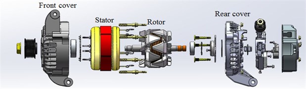
Fig. 2Geometric model of vehicle alternators
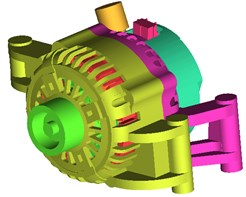
a) Complete motors
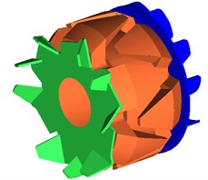
b) Rotor

c) Front fan
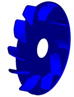
d) Rear fan
To improve computational efficiency and ensure computational accuracy, multiple computational domains were established for computation and comparison. Finally, a rather appropriate computational domain was selected, as shown in Fig. 3. The hemispheroid was the computational domain for the alternator to compute its aerodynamic noise. Meanwhile, the hemispheroid was 10 times of characteristic length (the axial maximum size of alternator) of alternators. The alternator was 0.1 m away from the ground. Such a computational domain could guarantee the full development of turbulent flow field. Fluid space was divided into stationary and rotating parts: The flow fields around front end cap, rear end cap, stator, rectifier and other parts were fixed part which remained stationary in the process of computation. Components including front fan, rear fan and claw poles were the rotating part and moved according to a given rotational speed. In the case of numerical computation, sliding grid technique was used to realize the relative motion of stationary part and rotating part. Mutual interface used “3 pairs of interfaces” to deal with stationary part and rotating part. Outlet boundary in the computational domain belonged to closed boundary condition. Only rotational speed was a known boundary condition, and it was 10000 r/min.
Fig. 3Computational domain for the aerodynamic noise of alternators
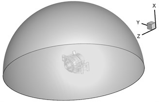
Fig. 4 presented the section view of grids obtained by adopting unstructured tetrahedral grids. The maximum size of grids on the surface of alternators was 2 mm. With a complex structure, front and rear blades rotated at a high speed. The maximum size of grids was within 0.2 mm and ciphered partially. The radial spacing of air gap between rotor and stator was 1.42 mm. Therefore, the maximum controlled grid size of air gap was 0.03 mm. To consider the impact of high-speed rotation of rotor on the flow of fluids more accurately, grid division of boundary layer was conducted on its surface. The growth rate of the boundary layer was 1.1. The first layer of grids on the surface of rotor was 6 layers of tri-prism grids with normal size 0.005 mm. Five groups of grids were used for trial computation in the model in this paper. The number of grids was 10.480.000, 13.460.000, 16.490.000, 18.770.000 and 19.330.000 respectively. When the number of grids was more than 18.770.000, the error of computational results was less than 0.15 %. Thus, the computational results in this paper indicated that the accuracy of grids satisfied the requirements of computation.
Fig. 4Computational grids of vehicle alternators
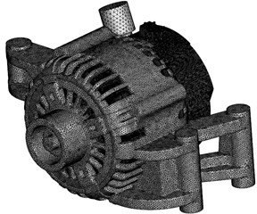
a) Grids of complete motor
b) The section view of grids
2.2. Mathematical model
2.2.1. Acoustic equations of aerodynamic noises
In 1952, British scientist Lighthill derived the basic equation of aerodynamic noises according to continuity equation and N-S equation:
wherein, represents Lighthill tensor, and it can be obtained according to the following equation:
wherein, is viscous stress tensor; is unit tensor; stands for undisturbed fluid density; represents the pulsating quantity of fluid density in moving flow field, ; is undisturbed fluid pressure; is the pulsating quantity of fluid pressure in moving flow field ; refers to the propagation velocity of sound in homogeneous medium.
Ffowcs Williams-Hawking equation [6] (FW-H equation for short) extended acoustic equations to considering the impact of boundary of moving solid. Its differential form is:
wherein, is gas pressure; stands for the normal direction; represents sound velocity; refers to normal velocity; is stationary pressure; is Lighthill stress tensor; is function; is Heaviside function.
The expression formula of FW-H model showed that sound pressure was caused by the particle force and acceleration of transient changes. The right side of Eq. (3) was monopole source, dipole source and quadrupole source. Neise [16-17] conducted analysis and showed that the main sound source of fan noises was dipole source caused by the unsteady-state turbulent flow of rotating blades. Therefore, noise source in this paper could be considered to be caused by the rotation of impeller and blades’ flapping air. This paper only considered the aerodynamic noise problem of alternators caused by dipole source.
2.2.2. Selection of turbulence model
Regarding the simulation of turbulent flow, the method of Reynolds-averaged Navier-Stokes equations (RANS) is widely used in engineering at present [20]. Its basic thought is to establish an empirical formula or equations to close and solve Reynolds equations. In steady-state simulation, this paper selected relatively extensive standard - model based on RANS simulation. Standard - model is a semi-empirical model based on two transport equations including turbulent kinetic energy and dissipation rate . Governing equations were:
wherein, is the density of gas; refers to the coefficient of dynamic viscosity of gas; stands for turbulent viscosity coefficient; represents the generation item of turbulent kinetic energy caused by average velocity gradient. Constants are 1.44, 1.92, 0.09, 1.0 and 1.3, respectively. Their values have been generally confirmed by experimental results.
Large eddy simulation filters out vortexes less than a certain scale in flow field by LES filter in the case of instantaneous motion of turbulent flow including pulsating motion, directly uses N-S equation to accurately solve the motion of all large-scale turbulent vortexes and computes the motion of filtered small-scale vortexes by means of sub-grid model. It is an ideal method which computes turbulent fluctuation [21, 22].
LES governing equation is still N-S equation of incompressible viscous fluid. In LES, large-scale velocity is filtering velocity and defined as:
wherein, is filtering velocity component; refers to filtering function which is used to filter the size of grids. If the filtering process could be exchanged with derivation process, the function was used for N-S equation of incompressible viscous fluid. Regardless of its form, the following equations could always be obtained:
wherein, is SGS Reynolds stress which is a new unknown variable to be modelized. To close equation set, SGS Reynolds stress had the following form according to the basic SGS model of Smagorinsky:
wherein, is unit tensor; refers to sub-grid turbulent viscosity coefficient; stands for the component of strain tensor of scale to be solved:
3. Aerodynamic noise characteristics of vehicle alternators
3.1. Computational method of aerodynamic noises
Commercial CFD software Fluent based on finite volume method was adopted to compute the equation set of unsteady aerodynamic characteristics of alternators at a given rotational speed. In the case of numerical computation, a steady-state computation was firstly conducted and steady-state result was taken as a transient initial condition in order to accelerate the convergence. When aerodynamic noise is computed, steady-state adopts MRF model for primary computation, with the results providing the initial value for the transient. In the transient computation, moving mesh technology, i.e., sliding mesh technology was adopted to realize the rotation of fan. Finally, LES method and Lighthill acoustics analogy theory were also used to compute the aerodynamic noise of the alternator.
Steady-state computation selected RNG - turbulent model and adopted SIMPLE algorithm for solution. Continuity equation used standard form for discretization. Momentum equation, turbulent kinetic energy equation and turbulent dissipation rate equation used second order upwind scheme for discretization.
Transient-state computation selected LES turbulence model. Sub-grid model was Smagorinsky -Lilly model. In the near-wall region, standard wall function was adopted. Time difference scheme was second order implicit expression. Pressure velocity coupling adopted PISO algorithm. Continuity equation used PRESTO. Momentum equation adopted Bounded Central Differencing. In the cases of steady-state and transient-state simulations, the interface adopted sliding grids. Convergence criterion was that the absolute value of variable residual error was less than 10-3 and the detection amount of inlet and outlet flow set on end cap presented periodical changes. In this case, computation at this stage could be ended. This paper set unsteady iteration time as 2×10⁻⁵s. Total interactive physical time was 0.2 s. Thus, it could be seen that the maximum frequency and frequency resolution of dynamic behavior characteristics of alternators were 25 kHz and 6 Hz respectively.
3.2. Flow filed structure around alternators
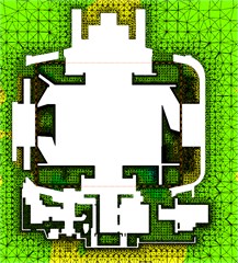
Fig. 5 presented contours for the distribution of relative pressure when the alternator operated at the rotational speed of 10000 r/min. As can be seen from Fig. 5(a), the pressure value of surface of front and rear blades was more than that of suction surface and pressure of stator and rotor claw pole was more than that of front and rear blades. Stator coil winding was in the low pressure area, which was caused by the small space between rotor and stator. As shown in Fig. 5(b), the positive and negative pressure of blades showed great differences in gradient, which indicated that sound source on the surface of blades should be one of important sources of aerodynamic noises. The leaf margin part of pressure surface had the greatest pressure and the positive and negative pressures of various blades were unevenly distributed, which should result from the asymmetric distribution of front blades.
Fig. 6 shows the velocity contour of axial section. It could be seen that the radial grids and bearing of end cap interfered with the airflow velocity of outlet. In the outlet area close to the wall, airflow velocity was low due to viscous force between airflow and wall. The trailing edge of fan blades had the maximum velocity. In the meanwhile, there was large velocity inside the claw pole. When the rotor rotated at a high speed, large velocity was conducive to the cooling of rotor winding. Such design was more beneficial to the cooling of cooling system of alternators.
Fig. 5Contours for the pressure of vehicle alternators
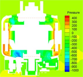
a) Axial section
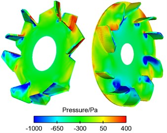
b) Front fan and rear fan
Fig. 6Velocity contour of axial section of vehicle alternators
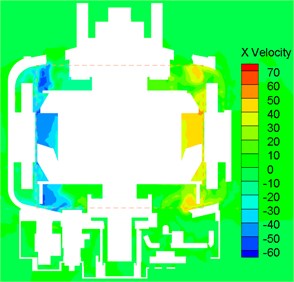
Fig. 7 shows the streamlines of front and rear fans of alternators. Thus, it could be seen that the front fan blades inhaled air from the axial grid of the front end cap to cool components including claw pole, coil and stator winding and exhausted air from the radial grid of the front end cap for cooling. The rear fan blades inhaled air from the axial shroud to cool electronic equipment like rectifier and components like stator winding coil and exhausted air from the radial grid of rear end cap for cooling. Therefore, it was clear that the design of fan blades met the cooling requirements of alternators.
Fig. 7The streamlines of front and rear fans of alternators
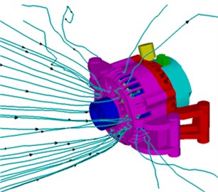
a) Front fan
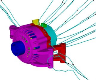
b) Rear fan
3.3. Aerodynamic noise source of alternators
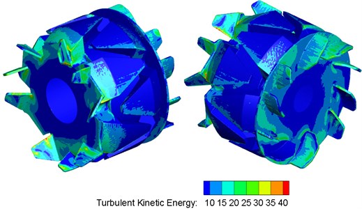
The aerodynamic noise source of alternators was mainly dipole noises. Dipole source on the surface of alternators was determined by fluctuation pressure on the surface of alternators. Namely, the size of fluctuation pressure on the surface of alternators could be used to reflect the radiation of far-field noises of sound production surface. According to two governing equations of flow field, turbulent kinetic energy equation and turbulent dissipation rate equation, it could be seen that the size of fluctuation pressure on the surface of alternators could use turbulent kinetic energy to evaluate noise distribution characteristics on the surface of alternators. Expression formula of turbulent kinetic energy is: . Fig. 8 showed the distribution diagram of turbulent kinetic energy on the surface of front and rear fans of alternators. As shown in Fig. 8, the peak value of turbulent kinetic energy of rotor could reach over 40 J/kg (rotational speed was 10000 r/min). Turbulent kinetic energy on the surface of front and rear blades was the highest. Turbulent kinetic energy on the surface of other parts was very small. At front and rear blades with large turbulent kinetic energy, the value of fluctuation pressure was also large and aerodynamic noises were also strong. Thus, it was clear that front and rear blades were main noise sources of alternators. In addition, the sound source area of the alternator was where airflow was easily separable and turbulent motion was very drastic.
Fig. 8Turbulent kinetic energy distribution of front and rear fans of alternators
The final goal of noise experiments was to reduce noises. Broadband noise source model could obtain the useful information of noise source and help to judge which part was the major cause of noises, but it was impossible to predict the radiation of visible noises. Broadband Noise Sources Model in Fluent noise module was used to compute the distribution of noise source on the surface of alternator. Data obtained by computation adopted 2 parameters as representation to reflect the aerodynamic noise of alternators: (1) Sound power: referred to the aerodynamic noise power of per unit volume of flow field space caused by the isotropic turbulence of alternators; (2) Sound power of surface: referred to the aerodynamic noise power of per unit area on the surface of alternators caused by the turbulence of the boundary layer.
Fig. 9 presented contours for the distribution of sound power levels of complete motors, front and rear fans when the alternator operated at the rotational speed of 10000 r/min. As shown in Fig. 9, the peak value of sound power levels on the surface of stator and rotor (front fan blades, claw pole and rear fan blades) reached up to over 90 dB. Sound power levels at front and rear end caps, shroud and other parts were small. On the surface of alternators with large sound power, the value of fluctuation pressure was also large and aerodynamic noises were also strong. Thus, it was clear that front fan, claw pole, rear fan and stator were main aerodynamic noise sources of vehicle alternators. In addition, the aerodynamic noise source area of the alternator was where airflow was easily separable and turbulent motion was very drastic (see Fig. 8). Thus, it could be seen that the aerodynamic noise of its alternator showed obvious noise reduction effect if the structure of front and rear fans of alternators was optimized (distribution angle of blades, the number of blades, the uneven distribution of blades and so on) and stator structure was rationally optimized. However, fan cooling efficiency and electromagnetic conductivity of alternators should be taken into consideration in the case of noise reduction.
Fig. 9Contours for the distribution of sound power levels of alternators
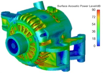
a) Complete motors

b) Front fan
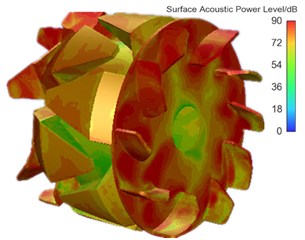
c) Rear fan
3.4. Aerodynamic noises of alternators in the far field
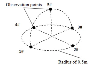
The stator was selected as aerodynamic noise source to numerically simulate the aerodynamic noise of alternators when the alternator operated at the rotational speed of 10000 r/min without loads. Observation points of aerodynamic noises in the far field were five observation points (observation point 1, 2, 3, 4 and 5) at the position which was 0.5 m away from the center of alternators. Fig. 10 presented the schematic diagram for the arrangement of observation points of aerodynamic noises in the far field.
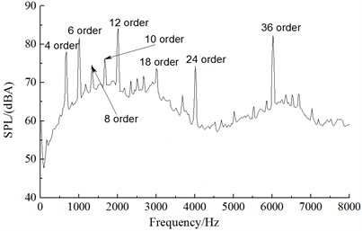
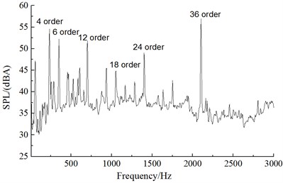
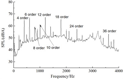
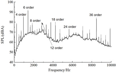
The value of fluctuation pressure obtained by numerical simulation was computed by FW-H to obtain the sound pressure level of aerodynamics noise of alternators at a constant rotational speed. Fig. 11 presented the linear spectrum of aerodynamic noises in the far field when the alternator operated at the rotational speed of 10000 r/min. Through FFT, the spectrum result of sound pressure fluctuation at a constant rotational speed was obtained. The principle of order analysis was applied. Usually, the relationship between order and rotational speed could be expressed as:
wherein, is signal frequency (Hz); represents order; rpm stands for the rotational speed of reference axis (r/min). Thus, order was directly corresponding to rotational speed. In essence, order analysis referred to a signal processing method of converting the signals of equal time interval into signals of equal angle interval and analyzing their frequency spectrums. Therefore, the subsequent analysis in this paper adopted the method of order analysis.
Fig. 10Schematic diagram for the observation points of aerodynamic noises
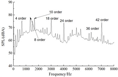
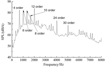
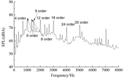
From the comparison of noise spectrums in Fig. 11, the aerodynamic noise of alternators was broadband noises, whose noise component was mainly composed of vortex noises (broadband noises) and rotation noises (order noises). An analysis on the order of noise spectrums of five observation points showed that the main influence orders of the front observation point (observation point 1) were the 4th, 6th, 8th, 10th, 12th, 18th, 24th and 36th orders; the main influence orders of the left observation point (observation point 2) were the 4th, 8th, 10th, 18th, 24th, 36th and 42th orders; the main influence orders of the rear observation point (observation point 3) were the 4th, 6th, 8th, 10th, 12th, 24th and 30th orders; the main influence orders of the right observation point (observation point 4) were the 4th, 6th, 8th, 9th, 12th, 18th, 24th and 30th orders; the main influence orders of the upper observation point (observation point 5) were the 6th, 10th, 12th, 18th, 30th, 36th and 42th orders. Therefore, the order analysis of various observation points showed that the main influence orders of aerodynamic noises of alternators were the 6th, 8th, 10th, 12th, 18th, 24th, 30th and 36th orders. Thus, it was clear that the numerical simulation results in this paper and test results of reference [14] showed a good consistency, indicating the correctness of numerical simulation results in this paper.
According to the vector synthesis method [19] of order noises and the numerical simulation results in this paper, the aerodynamic noise of the above orders could find corresponding sources of basis from motor structure. As shown in Fig. 2(c), the front fan of motor had 9 blades which were not distributed equidistantly. 3 blades formed a group; 9 blades were divided into 3 groups. 3 groups were uniformly distributed. The 12th order was taken as an example. Phase angles corresponding to the relative sound pressure vector of various blades were 0°, 684°, 1128°, 1440°, 2124°, 2568°, 2880°, 3564° and 4008°. There were only three vector potentials (see Fig. 12) on the vector diagram. In addition, synthetic trend was caused by the effect of superposition. The analysis on the composition result of the 6th and 18th orders was the same as above. Therefore, the noise of the 6th ( 1, 2, 3, …) order including 6th, 12th, 18th, … orders would be produced. The rear fan had 10 blades. In addition, one group was composed of 5 blades which were distributed symmetrically along the center (see Fig. 2(d)). Therefore, the noise of even orders including 4th, 8th, 10th, 12th, … orders would be produced. In the meanwhile, the rotor contained 6 pairs of claw poles. The aerodynamic noise of the 6th ( 1, 2, 3, …) order would be produced in the case of rotation. In addition, the stator had 36 slots. Through simulation, there was obvious backflow region around every slot when the alternator operated (as shown in Fig. 7). Noises of 36 orders would be produced.
Fig. 11Frequency spectrum of observation points of aerodynamic noises in the far field
a) Observation point 1
b) Observation point 2
c) Observation point 3
d) Observation point 4
e) Observation point 5
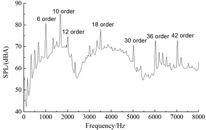
Similarly, this paper conducted an experimental test on the noise of vehicle alternators. Its experimental working condition also referred to reference [14]. Observation points of noises were 0.5 m away from the center of alternators. 5 observation points of noises were adopted, namely front, rear, left, right and upper observation points. In the case of conducting experiments, the rotational speed of alternators increased from 1000 r/min to 15000 r/min. The time of acceleration was 280 s. The adopted frequency of a single microphone was 20 kHz. The alternator operated under the working condition without loads. Namely, the impact of mechanical noises and electromagnetic noises caused by the operation of alternators was small and could be ignored. Fig. 13 presented the chromatogram of alternator noises changing with rotational speed at observation points 1 and 3. As shown in Fig. 13, the main influence orders of aerodynamic noises of alternators were the 6th, 8th, 10th, 12th, 18th, 24th, 30th and 36th orders, which was consistent with the working condition of numerical simulation in this paper. It showed the correctness of numerical simulation results in this paper. Meanwhile, the main influence orders of alternators were the 6th and 8th orders under the working condition of low speed. With the increase of rotational speed, other orders showed strong energy in the high frequency part, and it indicated that aerodynamic noises mainly presented in the high frequency.
Fig. 12Diagram for the vector synthesis of the 3kth order (k= 1, 2, 3, …) [19]
![Diagram for the vector synthesis of the 3kth order (k= 1, 2, 3, …) [19]](https://static-01.extrica.com/articles/18290/18290-img24.jpg)
Fig. 13Chromatogram of experimental noises of alternators
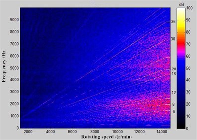
a) Observation point 1
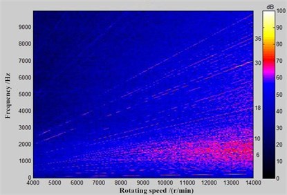
b) Observation point 3
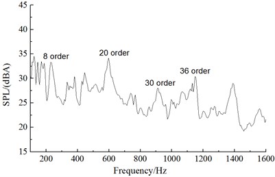
Fig. 14 presented the linear spectrum of aerodynamic noises in the far field when the alternator operated at the rotational speed of 1800 r/min, 3600 r/min, 6000 r/min and 12000 r/min. From the aerodynamic noise spectrum of alternators under the working condition of 1800 r/min in Fig. 14(a), the spectrum of rotation noises was not obvious and main orders were the 8th, 20th, 30th and 36th orders. Under the working condition of low rotational speed, the influence of single orders was not obvious. It was mainly vortex noises. From the aerodynamic noise spectrum of alternators under the working condition of 3600 r/min in Fig. 14(b), main influence orders were the 4th, 6th, 12th and 18th, 24th and 36th orders. The influence of single orders was obvious. From the aerodynamic noise spectrum of alternators under the working condition of 6000 r/min in Fig. 14(c), main orders were the 4th, 6th, 8th, 10th, 12th and 18th, 24th and 36th orders. The noise sound pressure level of the 6th, 12th and 18th orders was the largest. They were main influence orders. From the aerodynamic noise spectrum of alternators under the working condition of 12000 r/min in Fig. 14(d), main orders were the 4th, 6th, 8th, 12th, 18th, 24th and 36th orders. The noise sound pressure level of the 6th order was the largest. It was a main influence order. Thus, it could be seen that main orders were still the 6th, 8th, 10th, 12th, 18th, 24th and 36th orders and main influence orders were 6th, 8th, 12th, 18th and 36th orders with the increase of rotational speed. To reduce the aerodynamic noise of alternators, it was advised to optimize the structure of front and rear fans of aerodynamic noise source of alternators. Its noise reduction effect should be obvious.
Fig. 14Aerodynamic noise spectrums under different rotational speeds
a) 1800 r/min
b) 3600 r/min
c) 6000 r/min
d) 12000 r/min
4. Conclusions
This paper adopted LES and FW-H acoustic model to numerically compute the aerodynamic noise of alternators based on Lighthill acoustic theories, analyzed the aerodynamic flow behavior and aerodynamic noise characteristics of alternators in the far field and applied the method of order analysis to analyze the main influence orders of alternators. The following conclusions were obtained:
1) The combination of large eddy simulation and FW-H equation could well predict the vortex noises and rotation noises of cooling fan of alternators. The main aerodynamic noise sources of alternators were front fan blades, rear fan blades and stator structure. The 6th, 8th, 10th, 12th, 18th, 24th, 30th and 36th orders were main influence orders of aerodynamic noises. In addition, the numerically computational results presented a good consistency with the experimental test results, which further indicated the correctness of computational results in this paper.
2) The main action mechanism of cooling fan in the cooling system of alternators was as follows: Front fan blades inhaled air from the axial grid of front end cap to cool components including claw pole, coil, stator winding and so on and exhausted air from the radial grid of front end cap for cooing. Rear fan blades inhaled air from the axial shroud to cool electronic equipment like rectifier and components like stator winding coil and exhausted air from the radial grid of rear end cap for cooling.
3) Front and rear fans, rotor pole claw and slotted stator would cause aerodynamic noises. The front fan would cause the noise of the 6th ( 1, 2, 3, …) order including 6th, 12th, 18th, … orders. The rear fan would cause the noise of even orders including 4th, 8th, 10th, 12th, … orders. The rotor would cause the noise of the 6th ( 1, 2, 3, …) order. The stator would cause the noise of 36 orders.
4) When the alternator operated under different rotational speeds (1800 r/min, 3600 r/min, 6000 r/min, 10000 r/min and 12000 r/min), its main influence orders changed little and were mainly the 6th, 8th, 12th, 18th and 36th orders.
References
-
Zhang Y. D., Dong D. W., Yan B., Zhang J. Y., Wang Y. W. Numerical simulation analysis for aerodynamic noise of a vehicle alternator. Journal of Vibration and Shock, Vol. 35, Issue 1, 2016, p. 174-182.
-
Suh S. J., Chung J., Lim B. D., et al. Case history: noise source identification of an automobile alternator by RPM dependent noise and vibration spectrum analysis. Noise Control Engineering Journal, Vol. 37, Issue 1, 1991, p. 31-36.
-
Hui Y. N. Study on Vehicle Alternator Noise Testing and Noise Reduction Method. Xinan Jiaotong University, Chengdu, 2011.
-
Liu M., Dong D. W., Yan B., Chen Q. S., Tan X., Yang B. Test and analysis of noise characteristics and noise source of vehicle alternator. Journal of Chongqing Institute of Technology, Vol. 24, Issue 6, 2010, p. 13-17.
-
Lighthill M. J. On sound generated aerodynamically: Part 1: General theory. Proceedings of the Royal Society of London, Series A, Mathematical and Physical Sciences, Vol. 211, Issue 1107, 1952, p. 564-587.
-
Ffowcs-Williams J. E., Hawkings D. L. Sound generation by turbulence and surfaces in arbitrary motion. Philosophical Transactions for the Royal Society of London, Series A, Mathematical and Physical Sciences, Vol. 264, Issue 1151, 1969, p. 321-342.
-
Frederick D. M., Lauchle G. C. Aerodynamically-induced noise in an automotive alternator. Noise Control Engineering Journal, Vol. 43, Issue 2, 1995, p. 29-37.
-
Brungart T. A., Meyer G. A., Lauchle G. C. Flow in automotive alternators. Proceedings of the Institution of Mechanical Engineers, Part D: Journal of Automobile Engineering, Vol. 210, Issue 4, 1996, p. 283-292.
-
Fiedler J. O., Kasper K. A., De Doncker R. W. Acoustic noise in switched reluctance drives: an aerodynamic problem. Proceedings of Electric Machines and Drives, 2005, p. 1275-1280.
-
Zhang C. N., Wang Z. Z., Song Q. Research of noise source identification of traction motor system for electric vehicle based on microphone array. Proceedings of the Chinese Society for Electrical Engineering, Vol. 28, Issue 30, 2008, p. 109-112.
-
Wang Q., Yan K., Li H., et al. Motor noise source identification based on frequency domain analysis. Proceedings of ICMA, Changchun, 2009, p. 2373-2377.
-
Li H., Xu G., Yang C., Li X. W., Yang Y. L. Noise testing and characteristics frequency extraction method of sunroof motor. Proceedings of the Chinese Society for Electrical Engineering, Vol. 30, Issue 18, 2011, p. 87-92.
-
Cavagnino A., Saied S., Vaschetto S. Experimental identification and reduction of acoustic noise in small brushed DC motors. IEEE Transactions on Industry Applications, Vol. 50, Issue 1, 2014, p. 317-326.
-
Zhang Y. D., Dong D. W., Yan B., Hua C. R., Zhang S. J., Wang Y. W. Experiment study on aerodynamic noise of an automotive alternator. Noise and Vibration Control, Vol. 34, Issue 3, 2014, p. 107-110.
-
Fu W. R., Lu Y. M., Zhou Z. L., Hu T. Experimental research on electromagnetic noise characteristics of automotive alternators. Noise and Vibration Control, Vol. 34, Issue 6, 2014, p. 85-89.
-
Neise W. Review of noise reduction methods for centrifugal fans. Journal of Engineering for Industry, Vol. 104, Issue 2, 1982, p. 151-161.
-
Neise W. Review of fan noise generation mechanisms and control methods. An International INCE Symposium, Senlis, France, 1992, p. 45-56.
-
Kim W., Jeon W. H., Hur N., et al. Development of a low-noise cooling fan for an alternator using numerical and doe methods. International Journal of Automotive Technology, Vol. 12, Issue 2, 2011, p. 307-314.
-
Wang Y. W., Dong D. W., Xie X., et al. Spectral optimization of fan rotation noise based on vector composition method. Key Engineering Materials, Vol. 584, 2014, p. 131-136.
-
Versteeg H. K., Malalasekera W. An Introduction to Computational Fluid Dynamics. Longman Group Ltd., London, 1995.
-
Cui G. X., Xu C. X., Zhang Z. S. Progress in large eddy simulation of turbulent flows. Acta Aerodynamic Sinica, Vol. 22, Issue 2, 2004, p. 121-129.
-
Garnier E., Sagaut P., Adams N. Large Eddy Simulation for Compressible Flows. Springer, 2009.
About this article

