Abstract
An analytic dynamics model was presented for the three-stage planetary transmission in the pitch control reducer for MW wind turbine based on the lumped-parameter method. The mechanical characteristic of the contact components was analyzed using the stiffness factor method. All the stiffness sub-matrices were combined to form the overall stiffness matrix of the three-stage transmission. According to the analytic model and the parameters of the pitch control gearbox, the movement differential equations were solved to investigate the natural frequencies and the vibration modes. Then, the undamped and damping forced vibration response were studied. A test rig was set up to measure the vibration displacement of the ring at the second stage and the output shaft under the nominal load condition, the comparison of the analytic forced vibration response with the experimental results validates the effectiveness of the lumped-parameter dynamics model for the pitch control reducer. This paper provides a reference for the dynamics optimization of multistage planetary transmission.
1. Introduction
Planetary gear is an effective power transmission which has high torque-weight ratio, large speed reduction in compact volume and co-axial shaft arrangement. They are widely used in the automotive transmission, aircraft engine, pitch control and yaw drive in wind turbine. However, as the blade of wind turbine suffers load in wide frequency range, the pitch control reducer may have undesirable dynamics behavior which lead to unacceptable noise and damage. Therefore, it is important to research the vibration of the pitch control reducer. Dynamics analysis of planetary gear is essential for the reduction of noise and vibration.
Many researchers have developed lumped-parameter models and deformable gear models. Cunliffe, et al. [1] explored the characteristic of vibration modes of a 13-degree of freedom for single stage planetary system, and performed experiments to measure the input torque and planet pin load. Kahraman [2, 3] investigated the dynamic property of planet transmission for single stage using pure torsion vibration model, which involves translation and rotation degree of freedom. Lin and Parker [4-6] also presented a series of papers on planetary dynamics in which they examined the effect of support stiffness, mesh stiffness, inertia and operating speed on the natural frequency. The sensitivity of natural frequency to operating speed was also analyzed to estimate the gyroscopic effect. Yuksel and Kahraman [7] researched the dynamics of gear system including wear status, they defined the wear deepness of mesh gear pair in the wear model and effectively computed the contact pressure. Wu, et al. [8, 9] removed the rigid ring assumption to an elastic one, and the corresponding effects on the modal property were investigated. Sun and Shen [10] investigated the nonlinear frequency response characteristic of single stage planet system containing the fluctuating mesh stiffness, and the influence of the time-variant mesh stiffness, error and gear backlash on the nonlinear dynamics were also studied. Zhang, et al. [11] established an integrated dynamics model including time-variant mesh stiffness, gyroscopic effect and flexible ring to analyze the effect of flexibility of the ring on the natural performance of the planetary transmission. Xiao, et al. [12] researched the torsion dynamics about the three-stage planetary transmission in shield machine. There are three types of vibration modes: rotational mode, transnational and planet mode, these modes were associated in a compound planetary gear system [13, 14] and a high-speed planetary system with gyroscopic effects [15].
Finite Element Method (FEM) was also used to study planetary gear dynamics due to the fact that FEM can simulate the flexible components and analyze the contact status. Parker [16, 17] proposed finite element contact method to research the vibration of planetary gear, proving that the dynamic response is sensitive to the lower order vibration modes, but this finding need further experimental validation in order to study other gear system with the sensitive stiffness model. Abousleiman and Velex [18] developed a hybrid 3D finite element/lumped-parameter model and used it to analyze the planetary gear dynamics with flexible annulus and carrier [19]. Vijayakar [20, 21] developed a combined finite element and a contact mechanics model that permits relative coarse mesh near the contact region, this program can effectively solve the dynamics problem. However, Parker and Ambarisha [22] pointed out that the dynamics accuracy which the lumped-parameter model predicted equals that of the FEM model.
Through the survey of literature, it can be found that most research focuses either on rotational-transnational model for single stage or purely rotational dynamics for multistage. But many gearboxes are composed by multistage of planetary system in actual engineering, and all the components in planetary system have multi-degree of freedom. So, it needs to investigate the vibration of multistage planetary transmission including both translation and rotation degree of freedom for planet gearbox. Besides, all the aforementioned research has been little experimental work directing the various theoretical models since the work of Cunliffe, et al. [1]. In this paper, a vibration experiment is accomplished to verify the dynamics model.
2. Dynamics model of MW wind turbine pitch control reducer
2.1. Lumped-parameter analytical model
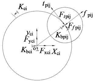
The lumped-parameter analytic model for single stage is established as shown in Fig. 1. The planet gears are equally spaced. All planets at the same stage are assumed to have identical mass, rotational inertia, support stiffness and time-invariant gear mesh stiffness. It is worthwhile mentioning that the gear backlash, radial bearing clearance, frictional force arising from tooth sliding motion, gear tooth spacing error and misalignment of the gears are not considered in this study.
Fig. 1Lumped-parameter analytic model
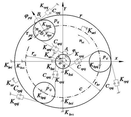
In the model, the gear mesh is treated as a linear time-invariant spring and a damping acting along the mesh line [10]. All other supporting bearings are modeled as linear springs. and present the supporting stiffness of the sun and ring at the stage, is the supporting stiffness of the planet at the stage. represents the supporting stiffness of the carrier at the stage. , and are the rotational stiffness of the sun, ring and carrier respectively, and and are the mesh stiffness between the planet and the sun or the ring, and and are the mesh damping.
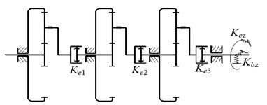
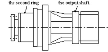
The configuration of the wind turbine pitch control reducer which consists of three stages of planetary system is shown in Fig. 2. The power is transformed from the sun at the first stage to the carrier at the last stage, which is connected to the output shaft of the pitch control reducer. The carrier connects the sun at the next stage by involutes spline. The spline connection is treated as a torsion spring between the carrier and sun, providing torsion support stiffness for the sun and carrier in the dynamics model. and are the supporting stiffness and torsion support stiffness of the output shaft respectively in the dynamics model.
Fig. 2Structure of the wind turbine pitch control reducer
2.2. Dynamics equations of the system
There are both three planets at the first and second stage, and four planets at the third stage, including the sun, ring and the carrier at all three stages, so the component numbers are 6, 6, 7 from the first stage to the last stage orderly, and then the output shaft connected to the third carrier also be considered, there are totally 20 components in the wind turbine pitch control reducer. Three degrees of freedom (DOF) have been considered for each component including one rotational DOF and two translational DOF, so 60 DOF for the wind turbine pitch control reducer must be researched.
The differential equations of motion for all the components in three-stage planet gear train are:
where is the inertia matrix, is the damping matrix, is the stiffness matrix, is the force vector of externally applied torque. is the vector of 60 degrees of freedom:
where is the lateral displacement in the fixed coordinate, is the vertical displacement and the rotational degree is replaced by the line displacement along the line of mesh, , where is the rotation angle of component and is the base circle radius for the sun, ring and planets and center radius for the carrier. and represent the radial and tangential displacement respectively in the movable coordinate on the planet.
The degree of freedom (DOF)1-3 are , , for the sun in the first stage, DOF 4-6 are , , for the ring, DOF 7-15 are , , for the planets, DOF 16-18 are , , for the carrier in the first stage. DOF 19-21 are , , for the sun in the second stage, DOF 22-24 are , , for the ring, DOF 25-33 are , , for the planets, DOF 34-36 are , , for the carrier in the second stage, DOF 37-39 are , , for the sun in the third stage, DOF 40-42 are , , for the ring, DOF 43-54 are , , the planets, DOF 55-57 are , , for the carrier in the third stage, DOF 58-60 are , , for the output shaft.
The inertia matrix in the differential motion equation is given as:
where , , and ( 1, 2, 3; 1, …, ) present the rotational inertia for the sun, ring, planet and the carrier, , , and present the mass for the sun, ring, planet and the carrier.
The stiffness factor method is suitable to model stiffness matrix for the problem containing plenty of complex coupled elements among these components. Each stiffness element in the stiffness matrix associates with the translational force and rotational moment in corresponding DOF. The stiffness is defined to be the force inducing one unit deformation. Mesh conditions of the sun and planet at all stages are treated identical. All the force, mesh stiffness and support stiffness for the sun and a planet are shown in Fig. 3.
Fig. 3The mesh between the sun and planet
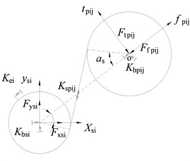
The mesh stiffness along the line of action between the sun and every planet can be transformed to , and directions in the fixed coordinate. Assuming that the sun deforms one unit in the direction, the support force and the mesh force of all planets will be applied on it, the decomposed components for all planets in the direction and the support stiffness are superimposed to compose the first element in the stiffness sub-matrix of the sun. There is no coupled element in and directions for the deformation of the sun in the direction, so the corresponding elements are 0 in the sub-matrix. The other stiffness elements can be obtained by the same method. The three order stiffness sub-matrix of the sun at single stage is:
where is the mesh stiffness between the sun and the planet at the stage, is phase angle of the planet, is external gearing angle. is torsion spring between the carrier and sun, is zero because there is no spline connected the first sun.
The force and mesh status between the planet and ring is shown in Fig.4 (a), the support spring, mesh spring, and the force of the planet are represented in the movable coordinate, while that of the ring are represented in the fixed coordinate. The force status of the carrier and planet is shown in Fig. 4(b).
Fig. 4The applied force status of mesh between components
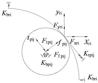
a) The ring and planet
b) The carrier and planet
The stiffness submatrix for the ring at the -stage is obtained by the stiffness coefficient method:
where is the mesh stiffness of the ring and the planet at the stage, is the internal mesh angle, .
The stiffness sub-matrix for the carrier at the stage can be obtained as follows:
Based on the applied force of the sun, ring and carrier on the planet in three directions in the movable coordinate, the sub-matrix for the planet is:
The other coupled stiffness elements between the sun and planet, the ring and planet, the carrier and planet in the whole matrix are also modeled, the stiffness sub-matrix coupled between the planet and sun at the stage is shown as follows:
The stiffness sub-matrix coupled between the planet and ring at the stage is:
The stiffness sub-matrix coupled between the planet and carrier at the stage is:
All the stiffness sub-matrices at the same stage are concentrated to form the whole stiffness matrix for each stage, which is 18×18 orders for the first and second stage and 21×21 orders for the third stage. The three subsystems of stiffness matrix are integrated as follows, where the uncoupled parts are replaced by sub-matrix 0:
According to the force status of the output shaft, the stiffness sub-matrix is:
The overall system stiffness matrix concentrating the three subsystems and the output shaft for the wind turbine pitch control reducer is:
Rayleigh damping is used in the dynamics equation which is proportion to the stiffness and inertia [6]:
Rayleigh damping coefficients and are defined by the method [23] shown in Eq. (3) according to the damping ratio :
There is a damping ratio corresponding to every order natural frequency . The first and second order damping ratios are treated as the same, which are 0.007 for the steel material here [22]. So, based on Eq. (6) and the first and second order natural frequencies, and can be obtained.
The applied force consisting of the input and output parts is referred to Eq. (4):
The external torque applies rotational force, so the force matrix for the three stages is referred as:
2.3. Structure parameters of the pitch control reducer
The structure parameters of the pitch control reducer are listed in Table 1. The module is 2 mm for the first and second stages, 4 mm for the third stage. The external and internal mesh angle is 23.7°, 22.8° and 20° from the first to the third stage.
The mesh stiffness for all contact gears is calculated by the Ishikawa method [24] according to the structure parameters in Table 1, and the rotation stiffness and support stiffness for each stage are calculated by static finite element method. The rotation stiffness and support stiffness calculated with the applied force and displacement in the FEM models are displayed in Table 2.
Table 1System parameters of the pitch control reducer
Stage | Part | Tooth number | Mass (kg) | Radius of base circle (mm) |
The first 2 mm 23.7° | Sun | 13 | 0.273 | 12.2 |
Ring | 83 | 4.227 | 78 | |
Planet | 34 | 0.835 | 32 | |
Carrier | 1.6 | 47 | ||
The second 2 mm 22. 8° | Sun | 16 | 0.644 | 15.04 |
Ring | 98 | 3.804 | 92.09 | |
Planet | 40 | 0.797 | 37.6 | |
Carrier | 2.74 | 56 | ||
The third 4 mm 20° | Sun | 13 | 1.405 | 24.43 |
Ring | 51 | 12.192 | 95.84 | |
Planet | 19 | 2.096 | 35.7 | |
Carrier | 7.747 | 64 | ||
Output shaft | 17.747 | 45 | ||
Table 2Stiffness in the model (N/mm)
Stiffness | The first stage | The second stage | The third stage |
Support stiffness | 3.16×10⁴ | 5.4×10⁴ | 7.19×10⁴ |
Support stiffness | 7.32×10⁵ | 8.63×10⁵ | 1.05×10⁶ |
Support stiffness | 8.34×10⁵ | 9.51×10⁵ | 1.35×10⁶ |
Support stiffness | 8.1×10⁴ | 3.72×10⁵ | 8.4×10⁵ |
Rotation stiffness | 7.06×10⁵ | 1.12×10⁶ | 1.3×10⁶ |
Rotation stiffness | 9.04×10⁵ | 1.23×10⁶ | 1.52×10⁶ |
Rotation stiffness | 4.08×10⁵ | 7.55×10⁵ | 1.12×10⁶ |
Rotation stiffness | 5.2×10⁵ | 7.41×10⁵ | 9.46×10⁵ |
Mesh stiffness | 8.16×10⁵ | 2.09×10⁶ | 3.17×10⁶ |
Mesh stiffness | 1.11×10⁶ | 2.52×10⁶ | 3.91×10⁶ |
3. Model analysis of the pitch control reducer
The natural frequencies and vibration modes provide important information of a system for avoiding away from resonance, minimizing response and optimizing the structural designing industry. Therefore, it is necessary to analyze the vibration modal. There are a large number of dynamic and static couple elements in the stiffness matrix in the dynamics equation, when solving the differential equations, they need decoupling with the Modal Summation Technique [25] to obtain the displacement vector. The responses for free vibration and forced vibration are calculated. The eigenvalues of the undamped linear time-invariant equations for free vibration satisfy the relationship [12] as follows:
where is the order natural frequency, is the order vibration mode for the corresponding component.
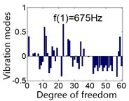
All system natural frequencies are listed in table 3 by solving Eq. (5). The first order natural frequency is 675 Hz and the 60 order frequency is 34906 Hz. The input rotational speed of the pitch control reducer is 1600 rpm, corresponding forced vibration frequency 26.67 Hz, which is less than the first order natural frequency, so the system is far away from the resonance.
A natural vibration mode is the vibration shape of the system at the corresponding order natural frequency, there are 3 basic kinds of vibration mode for planet transmission: rotational mode, transnational mode and planet mode, which are shown in Fig. 5(a), (b) and (c) respectively. The natural frequency in rotational mode is single root for the dynamics equation, all planets move in the same phase, the carrier, ring and sun rotate without transverse motion. The natural frequency in transnational mode is double roots for the dynamics equation, the carrier, ring and suntranslation have pure translation movement without rotation. The natural frequency in planet mode is multiple roots for the dynamics equation, the number of multiple roots is N-3 (N is planet number), the characteristic of the planet mode is that both translation and rotation motion of the carrier, ring and sun are zero, and only planet motion occurs.
Table 3Natural frequency for system vibration
Order | Frequency | Order | Frequency | Order | Frequency |
1 | 675 | 21 | 1849 | 41 | 6707 |
2 | 729 | 22 | 1897 | 42 | 6707 |
3 | 729 | 23 | 1897 | 43 | 7162 |
4 | 780 | 24 | 1975 | 44 | 7162 |
5 | 827 | 25 | 1988 | 45 | 7344 |
6 | 827 | 26 | 2251 | 46 | 7462 |
7 | 1114 | 27 | 2251 | 47 | 7462 |
8 | 1222 | 28 | 2355 | 48 | 8061 |
9 | 1243 | 29 | 3950 | 49 | 12011 |
10 | 1312 | 30 | 3961 | 50 | 12011 |
11 | 1312 | 31 | 4411 | 51 | 23406 |
12 | 1432 | 32 | 4411 | 52 | 23809 |
13 | 1432 | 33 | 4775 | 53 | 24697 |
14 | 1459 | 34 | 4924 | 54 | 24697 |
15 | 1615 | 35 | 4924 | 55 | 24991 |
16 | 1684 | 36 | 5758 | 56 | 26115 |
17 | 1684 | 37 | 5891 | 57 | 28305 |
18 | 1829 | 38 | 6096 | 58 | 24697 |
19 | 1829 | 39 | 6096 | 59 | 33863 |
20 | 1849 | 40 | 6404 | 60 | 34906 |
Fig. 5System vibration modes under mean gear mesh stiffness
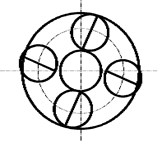
a) Rotational mode
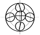
b) Transnational mode
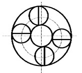
c) Planet mode
Fig. 6System vibration modes under mean gear mesh stiffness
a)
b)
c)
d)
e)
f)
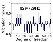
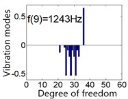
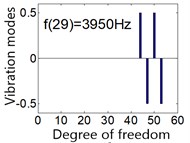
There are 60 order frequencies and vibration modes, in order to avoid long space displaying all 60 order vibration modes, partial vibration modes are shown in Fig. 6. Most components vibrate at the first three orders of natural frequency, the vibration modes of the first frequency 675 Hz and second frequency 729 Hz are shown in Fig. 6(a) and (b) respectively. is the order natural frequency, the ordinate is vibration mode for all 60 DOFs under the order natural frequency .
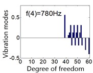
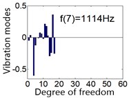
The rotational mode is independent of the transverse support of the carrier, ring and sun, the modes at the frequency 780 Hz and 1243 Hz are shown in Fig. 6(c) and (e) respectively. The translation mode is independent of the rotational support stiffness of the carrier, ring and sun, such as the mode at the frequency 1114 Hz shown in Fig. 6(d). The planet mode is insensitive to all the support stiffness for carrier, ring and sun, this mode occurs at the 3950 Hz as shown in Fig. 6(f).
4. Dynamic response of the pitch control reducer
4.1. Decoupling of system vibration model
There are a large number of coupled elements in the stiffness matrix, so it is necessary to decouple the vibration formulation when computing the dynamic response. The linear coordinate transformation method [12] transforms displacement vector for all DOFs from physical coordinate to modal coordinate, the transformation process will uncouple the matrix. The uncoupled equation is as follows:
where is main vibration mode matrix, is modal coordinate array.
Substituting Eq. (6) to dynamics Eq. (1), the vibration formulation of the undamped dynamic response is transformed as:
Assuming , . The system suffers external harmonic force, Eq. (7) will be transformed as:
where is basic force of the harmonic excitation, is the amplitude of the harmonic force, is harmonic angular frequency.
The vibration displacement in the modal coordinate of the three-stage planet can be calculated as:
where is vibration displacement in the modal coordinates.
Analytical solution of the vibration differential formulation in physical coordinate can be obtained by transformation with Modal Summation technique [25].
4.2. Undamped dynamic response
The input parameters of the pitch control reducer are rotational speed 1600 r/min and torque 38.2 Nm for the first stage, and the speed and torque at the other stages can be computed by the transmission ratio. Based on the above mentioned parameters of the pitch control reducer and the uncoupled process, the undamped dynamic response of the planet system can be solved. Partial results are given in Fig. 7(a)-(f) which present vibration displacement for some DOFs. The minimum vibration amplitude 0.113 mm belongs to the sun at the first stage in the rotation direction as in Fig. 7(a), the maximum displacement amplitude of the system is 0.589 mm which is related to the output shaft in the rotational direction.
Fig. 7Undamped displacement for part of response
a) Rotational displacement
b) Radial displacement
c) Lateral displacement
d) Rotational displacement
e) Lateral displacement
f) Rotational displacement
4.3. Damping dynamic response
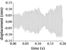
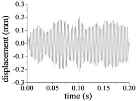
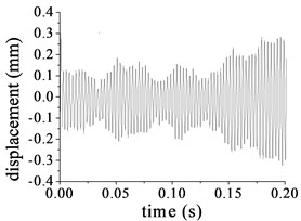
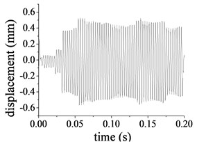
The Rayleigh damping coefficients and are 4.906 and 9.96×10⁻⁶ respectively [6]. Based on the calculated frequencies, Eq. (3) and the linear modal coordinate transformation in Eq. (6), substituting the proportion damping in Eq. (2) to dynamics Eq. (1), the damping dynamic response of the pitch control reducer under the nominal load condition is solved with the above Modal Summation Technique, part of the results is illustrated in Fig. 8(a)-(f). Compared to the undamped vibration system, dynamic response of damping vibration obviously decreases. The displacement amplitudes of the ring at the second stage illustrated in Fig. 8(c) and (d) are 0.092 mm in the direction and 0.283 mm in rotational direction. The peak-peak values are 0.193 mm and 0.621 mm in the and rotational directions respectively. As illustrated in Fig. 8(e) and (f), the displacement amplitudes of the output shaft are 0.304 mm in the lateral direction and 0.197 mm in rotational direction. The peak-peak value is 0.575 mm and 0.401 mm in the lateral and rotational direction respectively.
5. Experiment of dynamic response of pitch control
5.1. Testing rig
A testing rig is set up to measure the vibration performance of the pitch control reducer under the input speed 1600 r/min and input power 6.4 KW. A tested gearbox of wind turbine pitch control is tested with another accompanied gearbox on the rig as shown in Fig. 9(a). The power is supplied by a direct current motor equipped with electronic speed control, and then transmitted from the torque speed sensor, the tested gearbox, idler and the accompanied gearbox to the direct current generator. The rotational speed decreases through the tested gearbox and then increases through the accompanied gearbox. The vibration sensors, pressure sensors and temperature sensors are all powered and fastened on the tested gearbox. The PLC and a data acquisition card are equipped on the control cabinet orderly. The data collected by the sensors is tackled with the LabView software, and then displayed on the screen as shown in Fig. 9(b).
On the tested gearbox, two vibration sensors were located at the ring at the second stage and output shaft as shown in Fig. 10, three-dimension vibration acceleration in the radial, tangential and axis direction can be tested. The type of vibration sensor is CA-YD-141 in the two positions with 1-6000 Hz frequency response. The tangential displacement of the pitch control reducer in test rig is the rotational displacement in analytic model.
Fig. 8Damping displacement for part of response
a) Rotational displacement
b) Radial displacement
c) Lateral displacement
d) Rotational displacement
e) Lateral displacement
f) Rotational displacement
Fig. 9Test rig of the pitch control reducer
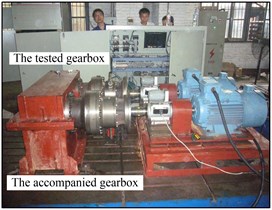
a) Testing part
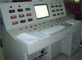
b) Operating and display part
Fig. 10Tested positions of the pitch reducer
5.2. Experiment data analysis
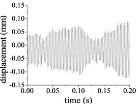
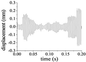
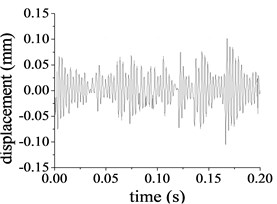
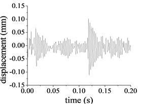
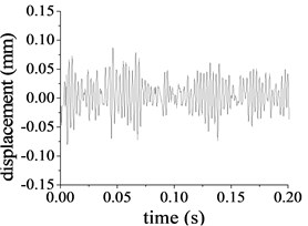
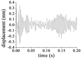
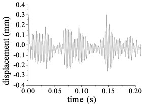
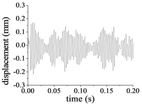
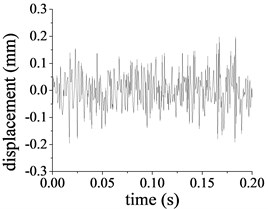
The vibration signal collected from the sensors is integrated to obtain the vibration displacement. The radial displacement and tangential displacement for the ring at the second stage are shown in Fig. 11(a) and (b) respectively. The peak displacement and peak-peak value for the ring is 0.104 mm and 0.210 mm respectively, the vibration amplitude of tangential displacement is 0.311 mm, while the peak-peak value is 0.632 mm. The radial displacement and tangential displacement for the output shaft are shown in Fig. 11(c) and (d). The radial peak vibration for the output shaft is 0.293 mm, while the peak-peak value is 0.597 mm, the peak tangential vibration and the peak-peak value of for the output shaft are 0.223 mm and 0.413 mm respectively.
Fig. 11Tested vibration displacement
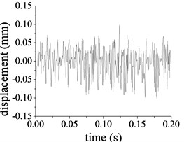
a) Vertical vibration of the ring at second stage
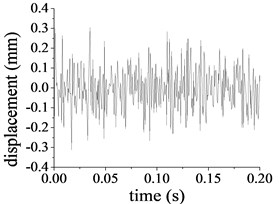
b) Rotational vibration of the ring at second stage
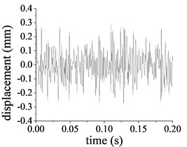
c) Vertical vibration of the output shaft
d) Rotational vibration of the output shaft
5.3. Validation of the theoretical model
The calculated damping displacement and tested vibration of the ring and the output shaft are illustrated in Table 4. The result shows that the amplitudes for the computation and test are generally similar. The tested tangential displacement amplitude and peak-peak value are close to the analytic rotational amplitude and peak-peak value.
Table 4Vibration comparison of computation and testing
Vibration displacement | Method | The second ring | Output shaft |
Amplitude (mm) | Analytic | 0.283 | 0.197 |
Test | 0.311 | 0.223 | |
Peak-peak amplitude (mm) | Analytic | 0.621 | 0.401 |
Test | 0.632 | 0.413 |
The small deviation of the amplitude for the ring exists between the computation and test because the rigid ring in the analytic model is flexible component in the tested gearbox and that the damping of stirring lubrication oil is not considered in the model. The vibration of the output shaft is influenced by other connected components, the vibration of the test rig and the operating of generator also affect the test vibration, so the tested vibration of the output shaft is little larger than the analytic result.
The experimental result generally agrees well with the theoretical computation and validates the effectiveness of the theoretical model. The lumped-parameter dynamics model for the MW wind turbine gearbox pitch control is fairly precise, and can provide theoretical basis for the research of the dynamics of the planet gearbox.
6. Conclusions
An analytic lumped-parameter dynamics model was established for the gearbox of MW wind turbine pitch control. The natural frequencies and the vibration modes of the gearbox were analyzed and three types of vibration modes were observed. It is found that the pitch control reducer is far away from resonance though calculation. Moreover, the undamped and damping forced vibration response were studied, it is shown that the undamped vibration is more severe than the damping vibration. Finally, the proportion damping forced response was compared against the physical experimental vibration result. The little deviation validates the effectiveness of the analytic model. This paper provides a reference of designing the dynamics characteristics of planetary gears.
References
-
Cunliffe F., Smith J. D., Wellbourn D. B. Dynamic tooth loads in epicyclical gears. Journal of Engineering for Industry, Vol. 94, 1974, p. 578-584.
-
Kahraman A. Planetary gear train dynamics. Journal of Mechanical Design, Vol. 116, Issue 1, 1994, p. 713-720.
-
Kahraman A. Natural modes of planetary gear trains. Journal of Sound and Vibration, Vol. 173, Issue 1, 1994, p. 125-130.
-
Lin J., Parker R. G. Analytical characterization of the unique properties of planet gear free vibration. Journal of Vibration and Acoustics, Vol. 121, 1999, p. 316-321.
-
Lin J., Parker R. G. Sensitivity of planetary gear natural frequencies and vibration modes to model parameters. Journal of Sound and Vibration, Vol. 228, Issues 1, 1999, p. 109-128.
-
Lin J., Parker R. G. Planetary gear parametric instability caused by mesh stiffness variation. Journal of Sound and Vibration, Vol. 249, Issue 1, 2002, p. 129-145.
-
Yuksel C., Kahraman A. Dynamic tooth loads of planetary gear sets having tooth profile wear. Mechanism and Machine Theory, Vol. 39, 2004, p. 695-715.
-
Wu X., Parker R. G. Modal properties of planetary gears with an elastic continuum ring gear. Journal of Applied Mechanics, Vol. 75, 2008, p. 1-10.
-
Parker R. G., Wu X. Vibration modes of planetary gears with unequally spaced planets and an elastic ring gear. Journal of Sound and Vibration, Vol. 329, 2010, p. 2265-2275.
-
Sun T., Shen Y. W., Sun Z. M., et al. Study on nonlinear dynamic behavior of planetary gear train solution and dynamic behavior. Journal of Mechanical Engineering, Vol. 38, Issue 3, 2002, p. 11-15.
-
Zhang J., Song Y., Wang J. J. Dynamic modeling for spur planetary gear transmission with flexible ring gear. Journal of Mechanical Engineering, Vol. 45, Issue 12, 2009, p. 29-36.
-
Xiao Z. M., Qin D. T., Wang J. H. Study on torsional dynamics of 3-stage planetary gears of main reducer used in driving cutter head of shield tunneling machine. China Mechanical Engineering, Vol. 21, Issue 18, 2010, p. 2176-2182.
-
Kiracofe D. R., Parker R. G. Structured vibration modes of general compound planetary gear systems. Journal of Vibration and Acoustics, Vol. 129, 2007, p. 1-16.
-
Guo Y., Parker R. G. Purely rotational model and vibration modes of compound planetary gears. Mechanism and Machine Theory, Vol. 45, 2010, p. 365-377.
-
Cooley C. G., Parker R. G. Vibration properties of high-speed planetary gears with gyroscopic effects. Journal of Vibration and Acoustics, 134, p. 2012-61014.
-
Parker R. G. A physical explanation for the effectiveness of planet phasing to suppress planetary gear vibration. Journal of Sound and Vibration, Vol. 236, Issue 4, 2000, p. 561-573.
-
Parker R. G., Vijayakar S. M. Non-Linear dynamic response of a spur gear pair: modeling experimental comparisons. Journal of Sound and vibration, Vol. 237, Issue 3, 2000, p. 435-455.
-
Abousleiman V., Velex P. A hybrid 3d finite element/lumped parameter model for quasi-static and dynamic analyses of planetary/epicyclical gear sets. Mechanism and Machine Theory, Vol. 41, 2006, p. 725-748.
-
Abousleiman V., Velex P., Becquerelle S. Modeling of spur and helical gear planetary drives with flexible ring gears and planet carriers. Journal of Mechanical Design, Vol. 129, 2007, p. 95-106.
-
Vijayakar M. A combined surface integral and finite- element solution for a three-dimensional contact problem. International Journal for Numerical Methods in Engineering, Vol. 31, 1991, p. 525-545.
-
Vijayakar M. Planetary 2D User’s Manual. Advanced Numerical Solutions LLC, Hilliard, OH 43026 USA, 2006.
-
Ambarisha V. K., Parker R. G. Nonlinear dynamics of planetary gears using analytical and finite element models. Journal of Sound and Vibration, Vol. 302, 2007, p. 577-595.
-
Wang D. D., Zhang Y. P., Yan J., et al. Calculation for the Rayleigh damping coefficients of multi-body structures. Machinery Design and Manufacture, Vol. 1, Issue 1, 2010, p. 230-231.
-
Li R. F. The Stiffness Analysis and Mending Tooth Shape Method of Gear Transmission. Chongqing, Press of Chongqing University, 1998.
-
Rao S. S. Mechanical Vibrations. Pearson Education Inc., 2004.
Cited by
About this article

The authors would like to thank anonymous referees for their helpful comments and suggestions, and this work is supported by National Natural Science Foundation of China (Grant No. 51705442 and 51575166), Educational Commission of HuNan Province of China (15A185) and Hunan Major Science and Technology Projects (2014FJ1002).
