Abstract
At present, a study on the end corrections of extended inlets and outlets of expansion chamber gas mufflers is relatively mature. However, such a research for an expansion chamber hydraulic suppressor has not been made yet. A coaxial and a non-coaxial expansion chamber configurations were introduced into hydraulic systems in this paper, and one-dimensional (1D) analytical approach was used to construct mathematical models of these structures and to verify it by experiments. After that, combined with the finite element method (FEM), researches on whether end corrections of the structures are applicable or not were studied.
Highlights
- The end correction theory is applied to expansion chamber hydraulic noise suppressors.
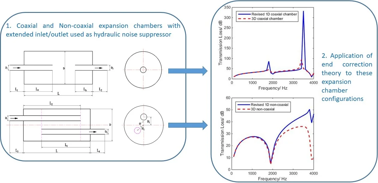
- A coaxial and a non-coaxial expansion chamber configurations are introduced into hydraulic systems.
- The finite element method and plane wave theory are employed to determine the end correction.
1. Introduction
Pressure pulsation waves propagating in a hydraulic pipe are generally considered to be plane waves propagating along the axial direction. However, the relevant data analysis indicate that even in the range of the cut-off frequency, the calculation results of the plane wave theory will gradually deviate from the measurement results as the frequency increases [1]. Though this deviation may be caused by the dissipation effect of higher modes which are excited by discontinuous areas, so end corrections can be introduced to improve the accuracy of the plane wave theory [1, 2].
Karal took the lead in studying the acoustic effects of an infinite circular pipe which cross section suddenly changed [3]. Kergomard and Garcia got the end correction of circular pipe radiation to semi-infinite space when the frequency tended to zero, and the results are similar to those obtained by Norris and Sheng [4, 5]. Peat used 1D analytical approach and FEM to study the effect of higher-order evanescent modes generated at the junctions and got the Karal correction factor [6]. Åbom studied expansion chambers with extended inlets and outlets and got the four-pole parameters considering the higher-order mode effects [7]. Sahasrabudhe and Munjal used the FEM to calculate the Karal correction factor of coaxial and non-coaxial discontinuities [8]. Torregrosa et al. applied the FEM to calculate the end corrections of the extended inlet and outlet of a coaxial expansion chamber muffler and studied the effects of diameter ratio for them [9]. Besides, Chaitanya and Munjal studied the effect of wall thickness of the inlet and outlet ducts [10]. Selamet and Ji used a three-dimensional (3D) analytical approach to analyze the end correction of a circular pipe connected with a circular asymmetric cavity [11]. Further, Kang and Ji analyzed the effects of chamber length, duct extension and diametric ratio on the end correction [12]. However, the focus of the existing literature [3-12] is on gas mufflers. No one has considered the higher-order mode effects for expansion chamber hydraulic suppressors with extended inlets and outlets.
In this paper, expansion chamber hydraulic suppressors were designed and validated experimentally. Then, the 1D analytical approach was combined with the 3D FEM to study whether the end corrections of extended inlets and outlets of coaxial and non-coaxial expansion chamber hydraulic suppressors are applicable or not.
2. Method and experiment
2.1. Method
When the noise frequency is lower than the cut-off frequency of a muffler, the plane wave theory can be used to analyze the filtering characteristics [1]. In order to apply this theory to the analysis of acoustic characteristics of hydraulic suppressors, the following assumption was made [1, 2, 13]:
1. The hydraulic oil in the pipeline has laminar flow without tangential velocity component.
2. Compared with the environmental state, pressure pulsation is regarded as a small amplitude disturbance and the Mach number is very low. Therefore, the mean flow can be neglected. Also, compared with the density of the medium, perturbations on density are very small.
3. Compared with the pipe diameter, the pipeline is longer, so the effect of the end point can be ignored.
4. The time dependence is assumed to be of the exponential form where is the angular frequency.
According to the above hypotheses, the 1D wave equation admits a general solution [1]:
and therefore:
where is the fluctuating pressure, is the axial coordinate, is the wave number, is the velocity of wave propagation, is the density of the medium, and are coefficients and stands for particle velocity. When using Eqs. (1), (2), the transfer matrix of a uniform tube can be written as:
where is the mass velocity, is the corresponding characteristic impedance. The transfer matrix for the th element can be denoted by . {, } is called the state vector at the upstream point , and {, } is called the state vector at the downstream point .
For types of extended-tube resonators, the equivalent impedance at the junction is given by Eq. (3), that is [2]:
where is the normal impedance.
Therefore [2]:
Further, transfer matrix of a lumped element can be written as [2]:
2.2. Experimental validation
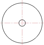
In order to validate whether this method is applicable to hydraulic systems, Eqs. (3) and (6) were used to simulate a hydraulic suppressor for a simple expansion chamber (SEC) and a double-tuned extended-tube chamber (DTETC), which are shown in Figs. 1, 2. Moreover, here stands for wall thickness.
Fig. 1Scheme of simple expansion chamber (SEC) hydraulic suppressor: L= 175 mm, D1=D2= 38.6 mm, D= 68 mm, t= 2 mm, L1=L2= 74 mm
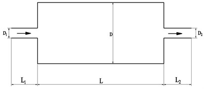
a) Elevation view

b) Left view
Fig. 2Scheme of double-tuned extended-tube chamber (DTETC) hydraulic suppressor: L= 175 mm, La=L/2, Lb=L/4, D1=D2= 38.6 mm, D= 68 mm, t= 2 mm, L1=L2= 74 mm

a) Elevation view
b) Left view
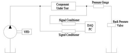
A scheme of the test rig can be seen in Fig. (3). Flow is provided to the system from a 9 piston axial piston pump driven by a variable frequency drive (VFD). The data from each pressure sensor are collected by a data acquisition card mounted inside of a PC.
Fig. 3Scheme of test setup for measurement of pressure pulsation of hydraulic suppressor
The hydraulic suppressors and their components are shown in Fig. 4.
The cut-off frequency, , of Figs. 1, 2 is given by [2]:
where is the tube diameter.
Fig. 4Experimental devices of SEC and DTETC: 1 – union joints, 2 – pressure sensors, 3 – inserted tubes, 4 – expansion chamber cavity
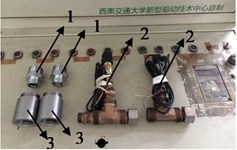
a)
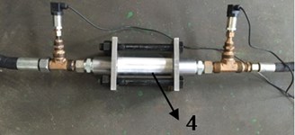
b)
Considering the limitation of experimental installations, the frequency band is defined as 2000 Hz. The given configurations have been validated below.
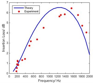
Figs. 5, 6 show the experimental validation for SEC and DTETC hydraulic suppressors. It is clear that predictions of the 1D analytical approach presented here compare well with those observed experimentally.
Fig. 5Comparison of theoretical IL of SEC with experimental measurements
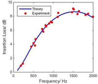
Fig. 6Comparison of theoretical IL of DTETC with experimental measurements
3. Finite element method
Acoustic domain of the hydraulic oil is discretized into a number of finite elements, and then the use of the Galerkin formulation for the acoustic system yields [1, 2, 10]:
where and are the stiffness and inertia matrices respectively. is the forcing vector proportional to the normal volume velocity boundary conditions imposed on the face of the hydraulic suppressor. At each frequency, the system of equations is set up and solved to obtain pressure distribution, . Once the system of equations is solved, the pressure pulsation and mass velocity are calculated at the inlet and outlet, respectively, and the transmission loss (TL) is calculated.
4. End corrections
Even though the study on the end corrections of the extended inlet and outlet of a expansion chamber muffler is mature, the applicability of this theory to hydraulic suppressors should be discussed, since the characteristics of hydraulic oil are different from those of gases. In order to account for coaxiality of inserted tubes, two different configurations were put forward as shown below.
4.1. Study on end corrections of coaxial expansion chamber hydraulic suppressor
The geometry shall be modeled as shown in Fig. 7.
The cut-off frequency of Fig. 7 is given by:
Considering this cut-off frequency, the research spectrum is defined as 4000 Hz. Predictions of the 1-D model were compared with those of the 3-D model, as shown in Fig. 8.
Fig. 7Coaxial expansion chamber hydraulic suppressor with extended inlet and outlet: D= 0.2 m, D1=D2= 0.03 m, L= 0.36 m, La= 0.18 m, Lb= 0.09 m, L1=L2= 0.07 m
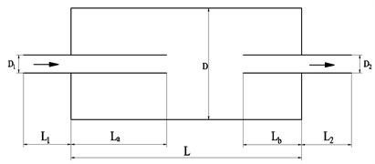
a) Elevation view

b) Left view
Fig. 8Comparison between 1-D and 3-D models of coaxial expansion chamber
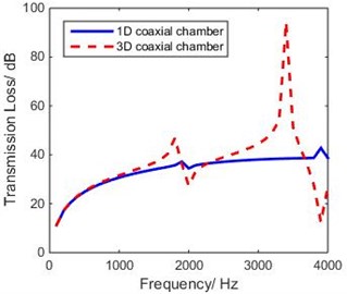
The Fig. 8 shows that the two peaks of the 3-D curve shift to the left of those of 1-D curve, which is similar to the results of corresponding mufflers. Hence, in reference to the acoustic length corrections of expansion chamber mufflers, the resonance peaks would occur at [2]:
where the effective length :
Therefore, the end correction is given by [10]:
where is the first resonance frequency evaluated by FEM, is the geometrical length of the inserted tube.
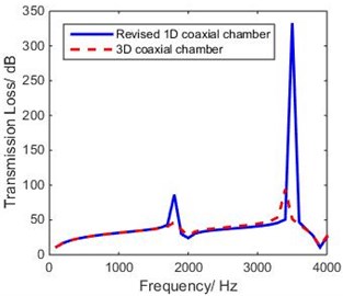
Fig. 9 shows that the resonance frequencies due to extended inlet/outlet are observed to occur at 1800 Hz and 3500 Hz. Using Eq. (12), the end corrections are calculated as 14.4 mm and 10 mm respectively. Predictions of the 1-D model match with those of the 3-D model only when we added the end corrections to the geometric length for use in the 1-D model [10], as shown in Fig. 10.
Fig. 10 shows that the first two peaks of the 1-D curve are in good agreement with those of FEM analysis; that means that the theory of end corrections is applicable to coaxial expansion chamber hydraulic suppressors.
Fig. 9Theoretical TL of extended inlet and outlet of coaxial expansion chamber
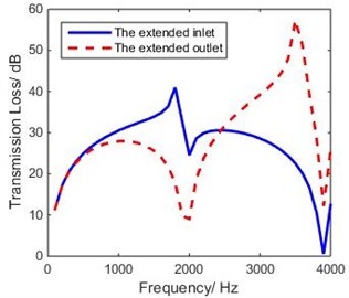
Fig. 10Comparison of theoretical TL of revised 1-D and 3-D model of coaxial expansion chamber
4.2. Study on end corrections of non-coaxial expansion chamber hydraulic suppressor
The theory similar to the one from 4.1 is used to study whether the end correction theory is applicable to non-coaxial expansion chamber hydraulic suppressors. The geometry need to be modeled as shown in Fig. 11.
Fig. 11Non-coaxial expansion chamber hydraulic suppressor with extended inlet and outlet: D= 0.2 m, D1=D2= 0.03 m, L= 0.36 m, L1= 0.28 m, L2= 0.3 m, L3=L4= 0.07 m, H1=H2= 0.04 m, θ= 180°
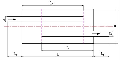
a) Elevation view
b) Left view
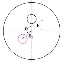
Predictions of the 1-D model were compared with those of the 3-D model, as shown in Fig. 12.
Fig. 12 shows that the first peak in the 3-D model is in good agreement with the corresponding peak in the 1-D model. However, the second peak in the 3-D model moved to the right of the corresponding peak in the 1-D model. Therefore, in order to consider the evanescent 3-D effects near the discontinuities, the geometric length in the 1-D model has to be increased by end corrections to achieve the effective acoustic length [10], which is the same as in 4.1. By using the FEM again, the theoretical TL of the extended inlet/outlet was obtained, as shown in Fig. 13.
Fig. 13 shows that the resonance frequencies due to extended inlet/outlet are observed to occur at 1200 Hz and 1300 Hz. Using Eq. (12), the end corrections were calculated as –8.3 mm and –10.8 mm respectively. The results of revised the 1-D model, and those of 3-D model were compared with them, as shown in Fig. 14.
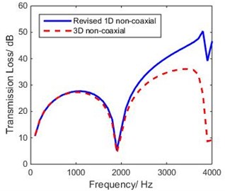
Fig. 14 shows that the second peak of the 1-D curve departs even farther from that of the FEM analysis; that means that the theory of end corrections is not applicable to non-coaxial expansion chamber hydraulic suppressors.
Fig. 12Comparison between 1-D and 3-D model of non-coaxial expansion chamber
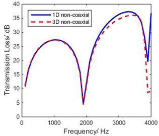
Fig. 13Theoretical TL of extended inlet and outlet of non-coaxial expansion chamber
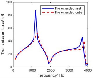
Fig. 14Comparison of theoretical TL of revised 1-D and 3-D model of non-coaxial expansion chamber
5. Conclusions
By using the 1D analytical approach and FEM, a preliminary study of end corrections for expansion chamber hydraulic noise suppressors was carried out, and the following conclusions were obtained:
1) As for coaxial expansion chambers, the results of revised 1-D methods are in good agreement with those of FEM; that means that the theory of end corrections is applicable to this structure.
2) For non-coaxial configurations, the revised 1-D curve departs even farther from the curve obtained by FEM; that means that the end corrections theory is not applicable. The reason may be that there are lots of physical parameters interacting with each other and even some nonlinear effects. Therefore, it needs to be further studied.
References
-
Ji Z. L. Acoustical Theory and Design of Mufflers. Science Press, China, 2015.
-
Munjal M. L. Acoustics of Ducts and Mufflers. Second Edition, Wiley, Chichester, 2014.
-
Karal F. C. Analogous acoustical impedance for discontinuities and constrictions of circular cross section. Journal of the Acoustical Society of America, Vol. 25, Issue 2, 1953, p. 327-334.
-
Kergomard J., Garcia A. Simple discontinuities in acoustic waveguides at low frequencies: Critical analysis and formulae. Journal of Sound and Vibration, Vol. 114, Issue 3, 1987, p. 465-479.
-
Norris A. N., Sheng I. Acoustic radiation from a circular pipe with an infinite flange. Journal of Sound and Vibration, Vol. 135, Issue 1, 1989, p. 85-93.
-
Peat K. S. Acoustical impedance at discontinuities of ducts in the presence of mean flow. Journal of Sound and Vibration, Vol. 127, Issue 1, 1988, p. 123-132.
-
Abom M. Derivation of Four-Pole parameters including higher order mode effects for expansion chamber mufflers with extended inlet and outlet. Journal of Sound and Vibration, Vol. 137, Issue 3, 1990, p. 403-418.
-
Sahasrabudhe A. D., Munjal M. L., Anantha Ramu S. Analysis of inertance due to the higher order mode effects in sudden area discontinuity. Journal of Sound and Vibration, Vol. 185, Issue 3, 1995, p. 515-529.
-
Torregrosa A. J., Broatch A., Payri R., et al. Numerical estimation of end corrections in extended-duct and perforated-duct mufflers. Journal of Vibration and Acoustics, Vol. 121, Issue 3, 1999, p. 302-308.
-
Chaitanya P., Munjal M. L. Effect of wall thickness on the end corrections of extended inlet and outlet of double-tuned expansion chamber. Applied Acoustics, Vol. 72, Issue 1, 2011, p. 65-70.
-
Selamet A., Ji Z. L. Circular asymmetric Helmholtz resonators. Journal of the Acoustical Society of America, Vol. 107, Issue 5, 2000, p. 2360-2369.
-
Kang Z. X., Ji Z. L. Acoustic length correction of duct extension into cylindrical chamber. Journal of Sound and Vibration, Vol. 310, Issues 4-5, 2008, p. 782-791.
-
Luo Z. C. Fluid Network Theory. China Machine Press, Beijing, 1988.
About this article

This research was supported by the China Scholarship Council.
