Abstract
Accurate and efficient estimation of tension in hangers is very important since hangers are the vital component of suspension bridges. But for hangers with shock absorber, the existing tension estimation methods are not suitable because they are based on a single cable model and cannot consider the effect of shock absorbers. To this end, the effect of the shock absorber is taken into account by using the degree-of-freedom condensation method, and a finite element method for tension estimation of hangers with shock absorber is proposed in this paper. Finally, the proposed method is applied in the Aizhai Bridge and Huangpu Pearl River Bridge to estimate the tension of hangers with shock absorber, the tested results show that as compared with other methods, the proposed method is a more accurate and convenient method for engineering application.
Highlights
- The paper presents a tension estimation method of hangers with shock absorber
- The effect of the shock absorber is taken into account by using the degree-of-freedom condensation method
- The proposed method is a more accurate and convenient one compared with other methods.
1. Introduction
Cable supported bridges are widely used nowadays since their advantage consists in the ability to cross large spans. In the range from 400 m to 2000 m, nearly 90 % of the bridges adopt cable supported systems [1]. Suspension bridge is a kind of cable supported bridges, which consists of two main cables, several vertical hangers and a main girder. Hangers are the critical components in suspension bridges to transfer load from the main girder to the main cables and towers. The cable tension of hangers are very important both in the stage of construction and maintenance [2-4]. Any changes of hanger forces will lead to the condition changes of the structure. So, it is desirable to estimate the tensions in hangers accurately both in the construction stage and in the maintenance stage.
In general, there are two categories of cable tension estimation method, one is the direct method; the other is the indirect method. The direct method consists in measuring the cable force directly by load transducer which should be installed at the cable anchorage during construction. This method can determine the cable tension directly and accurately, but the cost is very expensive. The indirect method consists in measuring other parameters rather than force and using mechanical models to calculate the cable tensions from the other tested parameters. Frequency and magnetic flux of cable are the commonly used two indirect parameters. The method using the magnetic flux to calculate the cable tension is called as the magnetoelastic method. It is a new recently developed approach, and its cost is very expensive [5, 6]. The method using the frequency to calculate the cable tension is called as the frequency-based method. Since the frequency test is a very mature technology with easy operation and low cost, the frequency-based method becomes the most commonly used method in practical applications [7-12].
Relationship between the frequency and cable tension is the key factor in the frequency-based method which determines the accuracy of estimation result. There are many formulas to calculate the cable force using the natural frequencies of the cable. The first kind is the taut string theory formula [13], it assumes that cable is an ideal string without bending stiffness which may lead to errors because the bending stiffness of the cable is considerable [14]. The second kind is the beam theory formula which is derived from the vibration equation of an axially loaded beam with simple supports [15]. This formula has considered the bending stiffness of the cable and the results are more accurate than the taut string theory formula. But it cannot be used to calculate the tension in cables with complicated boundaries other than simple supports. The third kind is called as practical formulas, which are fitting equations by using numerical methods such as the finite element method. There have been many practical formulas proposed, such as Zui et al. [16], Mehrabi et al. [17], Ren et al. [18], Fang et al. [19], Huang et al. [20] and so on.
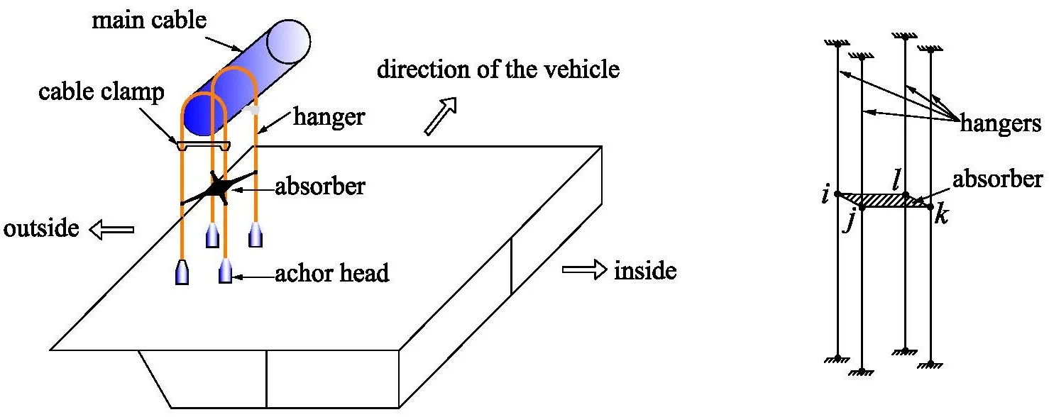
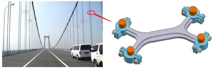
However, most of the aforementioned formulas assume that the cable is restrained only at the ends, so they are not suitable to cables with intermediate supports [21]. In a suspension bridge, four hangers at the same lifting point are normally connected by a shock absorber at the middle of the cable in order to control the hanger vibration (see in Fig. 1). Therefore, due to the effect of the shock absorber, the conventional frequency-based formulae for cable force estimation are inapplicable [22]. In order to solve this problem, a tension estimation method of hangers with shock absorber in suspension bridge by using the finite element method is proposed in this paper.
Fig. 1Sketch of shock absorber
2. Element introduction
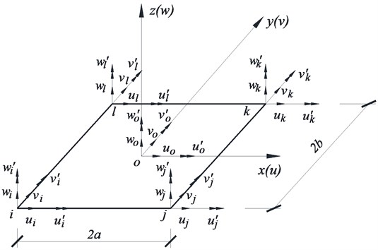
Fig. 2 presents a model for a spatial beam element with 2 nodes and 6 degrees of freedom (DOFs) at each node. The local coordinate is with denoting the axial direction of the cable and , axes denoting the transverse directions of the cable. The length and density of element are and , respectively.
Fig. 2Nodal displacements of the element
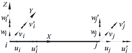
As shown in Fig. 2, the nodal displacement vector of the element is:
Depending on the vibrational properties, the nodal displacements are generalized to four sub-vectors as follows:
In which is the axial vibration vector, and are the transverse vibration vectors along and axes, respectively, is the torsional vibration vector. Correspondingly, the stiffness and mass matrices are also divided into different kinds of sub-matrices.
2.1. Matrices of axial stiffness and mass
The general solution of the axial vibration is [23]:
where is the function of displacement, is the frequency of vibration, is the phase angle.
Assume that the interpolation function of axial displacement is the linear function as follows:
where and are undetermined coefficients.
On the other hand, the element displacement can be calculated by multiplying the interpolation function and the nodal displacements vectors, the equations are as follows:
where is called as the shape function of the axial displacement and expressed as:
By using the general derivation method proposed by literatures [24], the stiffness and mass matrices can be derived as follows:
2.2. Matrices of bending stiffness and mass
There are two transverse axes, and . According to the assumptions given in Section 2.1, the displacements of direction are assumed to be independent of those in the direction. And the cross-section of the cable is a totally symmetrical section (circle shape) with isotropic material, so the stiffness and mass matrices along and axes will be the same. Only the derivation of the stiffness and mass matrices along the axis are presented.
The equilibrium equation of a cable subjected to a tension can be written as:
where is the Young’s modulus of the material, is the second moment of area, is the transverse displacement, and is the tension. The general solution of Eq. (9) is:
where, , , , are undetermined coefficients, and [16].
For the transverse vibrations, the element displacement can be calculated by multiplying the interpolation function and the nodal displacements vectors as follows:
where is called shape function of the transverse displacement and expressed as:
where:
In the above formulas, ‘’ is an abbreviation for the hyperbolic sine function ‘’ and ‘’ is an abbreviation for the hyperbolic cosine function ‘’.
The bending strain energy caused by the bending deformation is [25]:
The potential energy caused by the cable tension is:
Adding Eqs. (17) and (18), the total potential energy of the element caused by transverse bending is:
By using variational principle, the element stiffness matrix is obtained as:
where:
The potential energy caused by the inertia force is:
In which .
By using variational principle, the element mass matrix is obtained as:
where:
In a similar way, the element stiffness matrix and mass matrix along the axis can be obtained as:
where:
2.3. Matrices of torsional stiffness and mass
Assume that the interpolation function of torsional displacement is a linear function which is the same as the axial displacement, using the derivation method proposed in Section 2.1, the matrices of torsional stiffness and mass for the element can be obtained as:
where , , are the shear modulus, torsional moment of inertia and polar moment of inertia, respectively.
2.4. Assembling of element stiffness and mass matrices
The vector of nodal displacement for the beam element with 12 DOFs is:
So, the matrices of stiffness and mass for the element can be described as follows:
where the detailed expressions of , , , are given in Eqs. (7), (20), (25) and (27). And the detailed expressions of , , , are given in Eqs. (8), (23), (26) and (28).
3. Consideration method of shock absorber
3.1. Simplified mechanical model
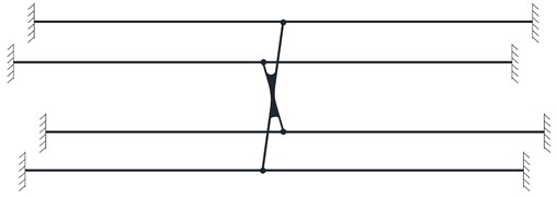
A system consisted of 4 hangers, 4 anchor heads, 2 cable clamps and 1 shock absorber is shown in Fig. 3. These 4 hangers are connected by a shock absorber at the middle and suspended on the main cable through cable clamps at the upper ends and connected to the stiffening girder through anchor heads at the lower ends. Since the cable clamps and anchor heads have strong fixation capacity, the boundary conditions of the hangers can be considered as fixed boundaries at both ends. And since the stiffness of the shock absorber is much greater than that of the hangers, it can be modeled as a rigid plate which plays the role of restraint to ensure the vibration compatibility of the 4 hangers in the system. According to the above assumption, the mechanical model of the hanger system can be simplified as show in Fig. 4.
3.2. Condensation method of dofs for shock absorber
The shock absorber can be regarded as a rigid body since its in-plane stiffness is much larger than that of the hangers. According to the deformation compatibility conditions, the finite element model of the hanger system described in Fig. 4 can be simplified. The finite element model shown in Fig. 5 is taken as an example to describe the condensation method of DOFs for the shock absorber. Without loss of generality, we assume that the four nodes , , k, in Fig. 5 all have six DOFs and the displacement vector of arbitrary node (, , , ) can be written as:
Fig. 3Sketch of hanger system
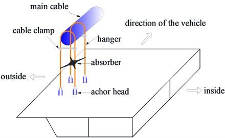
Fig. 4Mechanical model of hanger system
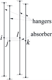
Fig. 5Nodal displacements of shock absorber element
The nodal displacements, geometric dimensions and local coordinates of the shock absorber element are shown in Fig. 5. The centroid of the shock absorber is denoted as “” and it also has six DOFs as follows:
According to the rigid body kinematic theory and ignoring the small terms higher than the second order, the displacements of the four corner nodes (, , , ) and those of the centroid () have the following relationship:
Can be rewritten as a matrix form as follows:
where, and are displacement vectors of the corner nodes and the centroid respectively, is a 6×6 transformation matrix of the displacements between the corner nodes and the centroid, is a 3×3 identity matrix, is a 3×3 null matrix and is a 3×3 matrix, where:
By using Eq. (38), the constraint relationship between the nodes of the shock absorber is established, and the contribution of the shock absorber to the stiffness of the whole hanger system is therefore considered.
In the global hanger system, the mass of the shock absorber also can be considered as concentrated on the centroid by using the concentrated mass method, then the mass matrix of the centroid node can be written as:
According to Eqs. (39) and (40), the finite element program for tension estimation of the hanger system can be easily developed, and its specific process for this is consistent with the general finite element programming [24].
3.3. Frequency equation of hanger system
The hanger system is discretized according to the actual demands. It must be noted that the element nodes must be assigned at the connection of the cable and the shock absorber in order to avoid additional DOFs conversion. The DOFs of the four nodes of the shock absorber are concentrated to the centroid of the shock absorber by using the static condensation method, also known as the Guyan reduction method [24]. The Guyan reduction method is a dimensionality reduction method, it can reduce the number of DOFs through ignoring the inertial terms of the equilibrium equations and expression of the unloaded DOFs which are also called as slave DOFs in terms of the loaded DOFs which are also called as master DOFs.
In Eq. (38), is the master DOF, is the slave DOF. From Eq. (38), we know that the whole DOFs for the shock absorber are:
The equation of free vibration for the shock absorber is:
The DOFs can be reduced by using the relationship given by Eq. (37) and therefore the influence of the shock absorber is taken into account. Specifically, by substituting Eq. (41) into Eq. (42) and multiplying by at the both side of the equation, it can be obtained:
where:
By partitioning the above system of linear equations with master DOFs and slave DOFs, the static equilibrium equation may be expressed as:
where is the force vector and 0 is the zero vector. Focusing on the lower partition of the above system of linear equations, the slave DOFs are expressed by the following equation:
Solving the above equation in terms of the master DOFs leads to the following dependency relations:
Substituting the dependency relations on the upper partition of the static equilibrium problem condenses away the slave DOFs, leading to the following reduced system of linear equations:
Comparing Eq. (47) with Eq. (48), it can be obtained:
After substituting Eq. (49) into Eq. (44), the reduced stiffness and mass matrices and can be obtained as:
Obviously, the reduced matrices and are still symmetric matrices. However, their orders are reduced compared with those of and . They only contain DOFs of the master node (centroid node).
Accordingly, the frequency equation with reduced DOFs for the hanger system can be obtained as follows:
The relation between the frequency and the cable tension can be obtained by solving the above frequency equation.
3.4. Cable tension estimation program
With Eq. (51), the tension force can be calculated by an iterative program developed in MATLAB as follows.
(a) In ambient conditions, acceleration sensors are installed at the cables to measure the frequencies, and a number of natural frequencies of the hanger are extracted. Using the taut-string formula, an initial value of the cable tension is used to start the iteration. Where is the measure first-order circular frequency.
(b) Substituting into Eq. (51), and solving the eigenvalue problem yield a new value of circular frequency ω of the hanger system. If 0.001, then the tension is , and the iteration is stopped. Otherwise, the convergence condition is not satisfied, let and repeat iteration until it is satisfied. At the end of iteration the tension is equal to the final value of .
4. Approach for shock absorber modeled as elastic support
For the above hanger system, the shock absorber can also be considered as a constraint of one cable to another, and thus the hanger system can be modeled as a single cable with an intermediate elastic support. And then its tension can be estimated by using the finite element method for cable with intermediate supports proposed by Wang et al. [26]. For the hanger system shown in Fig. 6(a), it can be modeled as a single cable with intermediate elastic supports shown in Fig. 6(b).
Fig. 6Hanger system simplified to single cable: a) hanger system with shock absorber, b) single cable with intermediate supports
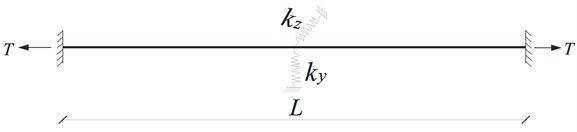
In Fig. 6(b), , are equivalent stiffness which can be calculated by the following equation:
where and are the tension and the total length of the cable, respectively. After such simplification, the finite element model can be established using the method proposed by Wang et al. [26], and then the internal forces of the hangers can be identified.
5. Case study
5.1. Huangpu pearl river bridge
The Huangpu Pearl River Bridge is a key project on the second ring highway of Guangzhou, which is the largest bridge in the Southern China. The main bridge is a single span steel box girder suspension bridge with the main span of 1108 m (Fig. 7). The main cable arrangement is 290+1108+330 m with the sag-to-span ratio of 1/10. All hangers which are longer than 20 m have absorbers installed (these hangers are No. 1-26 and No. 60-85).
When the bridge was constructed completely but before it was opened to traffic, the natural frequency of all hangers was measured by using the Dynamic Testing System (DASP) and the INV9828 type acceleration sensor (China Orient Institute of Noise & Vibration), and some of the results for hangers W1 to W8 on the upstream side are listed in Table 1. There are four hangers for each location, here only the test results for one of them are listed.
Fig. 7Elevation of Huangpu pearl river bridge
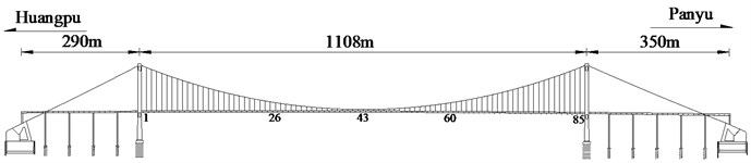
Table 1Frequency test results for W1-W8 hangers of Huangpu pearl river bridge (unit: Hz)
Hanger No. | W1 | W2 | W3 | W4 | W5 | W6 | W7 | W8 |
1.416 | 1.563 | 1.652 | 1.661 | 1.758 | 1.953 | 2.018 | 2.149 | |
2.832 | 3.125 | 3.296 | 3.321 | 3.711 | 3.907 | 4.102 | 4.297 | |
4.249 | 4.688 | 4.956 | 5.079 | 5.469 | 5.86 | 6.055 | 6.446 | |
5.665 | 6.055 | 6.616 | 6.641 | 7.032 | 7.813 | 8.009 | 8.595 |
The cross-sectional area of the hanger is 0.00149 m2, the mass per unit length is 13.6 kg/m and the moment of inertia used is 3.067e-8 m4. Based on these parameters, the cable force of the hanger is calculated by the proposed method as shown in Table 2. It can be seen that the calculation results by the proposed method are in good agreement with the design values with a difference lesser than 3.5 %, which verifies the accuracy of the proposed method.
Table 2Comparison of estimated tension for hangers W1-W8 of Huangpu pearl river bridge
Hanger No. | W1 | W2 | W3 | W4 | W5 | W6 | W7 | W8 |
Calculated cable tension (kN) | 359.9 | 357.8 | 354.8 | 355 | 354 | 371 | 356.2 | 362.8 |
Designed cable tension (kN) | 365.5 | 365.5 | 365.5 | 365.5 | 365.5 | 365.5 | 365.5 | 365.5 |
Differences (%) | 1.52 | 2.12 | 2.94 | 2.87 | 3.15 | 1.50 | 2.55 | 0.75 |
5.2. Aizhai bridge
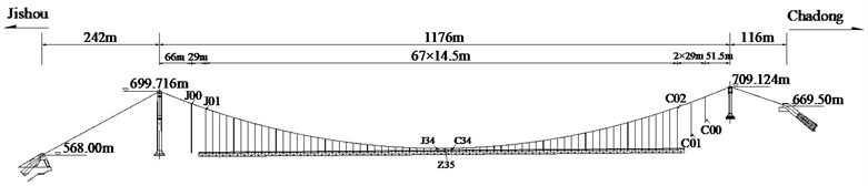
The proposed method is also used for a case study for the Aizhai Bridge in the Changsha-Chongqing expressway across the Dehang Grand Canyon in the west of Hunan Province near the city of Jishou, which is an iconic suspension bridge in China. The layout of the main cables of the bridge is 242+1176+116 m, with a rise/span ratio of 1/9.6. A steel-truss structure was used as the stiffening girder with a total length of 1000.5 m. The layout of the bridge is shown in Fig. 8 [27].
Fig. 8Elevation of Aizhai bridge
All hangers which are longer than 20 m have absorbers installed (these hangers are numbered as C02-C20 and J01-J20). In this paper, the frequencies of the C02-C20 hangers before and after installation of the shock absorber were measured by using acceleration sensors. The measured frequency and estimated cable tension of the hangers are shown in the Table.3. It should be noted that the cable tension estimation before absorber installation is using the taut string method and the cable tension estimation after absorber installation is using the proposed method. Theoretically, because the bridge deck is not subjected to any additional load before and after installation of absorbers, the internal forces of the hangers should be the same before and after installation of absorbers. Moreover, before the absorber installation, the cables have very small relative bending stiffness, so the taut string method has high accuracy, and the estimated results can be seen as the actual one [28]. From Table 3, it can be seen that the errors of estimated tensions from these two kinds of method are no more than 2 %, which verifies the accuracy of the proposed method.
Table 3Comparison of estimated tension for C02-C10 hangers of Aizhai bridge
Hanger No. | (m) | Fundamental frequency (Hz) | Cable tension (kN) | Differences of tension (%) | ||
Before absorber installation | After absorber installation | Before absorber installation | After absorber installation | |||
C02 | 84.593 | 0.738 | 1.480 | 527 | 530 | 0.56 % |
C03 | 80.218 | 1.109 | 2.218 | 503 | 503 | 0.10 % |
C04 | 75.476 | 1.177 | 2.358 | 497 | 498 | 0.33 % |
C05 | 70.884 | 1.251 | 2.504 | 510 | 511 | 0.16 % |
C06 | 66.444 | 1.347 | 2.698 | 505 | 506 | 0.29 % |
C07 | 62.154 | 1.421 | 2.848 | 495 | 497 | 0.45 % |
C08 | 58.019 | 1.520 | 3.049 | 510 | 513 | 0.61 % |
C09 | 54.034 | 1.641 | 3.293 | 512 | 515 | 0.63 % |
C10 | 50.200 | 1.767 | 3.537 | 510 | 510 | 0.14 % |
5.3. Comparison and discussion
For hangers with shock absorber, there are four kinds of method can be used to identify the cable tension. Method 1 is the taut string theory method. When using this method the shock absorber should be removed first before measuring the frequencies. Method 2 is the finite element method of tension identification for cables with intermediate supports described in Section 4. Method 3 is the “form finding” method proposed by Huang et al. [28]. And Method 4 is the proposed method in this paper. The comparison between these four methods is shown in Table 4. The data in parentheses represent the relative error between the estimated cable tension and the design value.
Table 4Comparison of estimated cable tensions by different methods for Aizhai bridge (unit: kN)
Hanger number | Designed value | Taut string method | Intermediate support FEM | Form finding method | Proposed method |
C02 | 526 | 527 (–0.2 %) | 540 (–2.7 %) | 509 (–3.2 %) | 530 (–0.8 %) |
C03 | 507 | 503 (0.8 %) | 515 (–1.6 %) | 498 (1.8 %) | 503 (0.8 %) |
C04 | 501 | 497 (0.8 %) | 513 (–2.4 %) | 485 (3.2 %) | 498 (0.6 %) |
C05 | 501 | 510 (–1.8 %) | 513 (–2.4 %) | 486 (3.0 %) | 511 (–2.0 %) |
C06 | 501 | 505 (–0.8 %) | 522 (–4.2 %) | 486 (3.0 %) | 506 (–1.0 %) |
C07 | 501 | 495 (1.2 %) | 510 (–1.8 %) | 487 (2.8 %) | 497 (0.8 %) |
C08 | 501 | 510 (–1.8 %) | 509 (–1.6 %) | 487 (2.8 %) | 513 (–2.4 %) |
C09 | 500 | 512 (–2.4 %) | 516 (–3.2 %) | 487 (2.6 %) | 515 (–3.0 %) |
C10 | 500 | 510 (–2.0 %) | 513 (–2.6 %) | 488 (2.4 %) | 510 (–2.0 %) |
From Table 4, it can be seen that all the methods can identify the cable tension approximately with a relative error of no more than 5 %. And as compared with Method 2 and Method 3, the results of method 1 and the proposed method are much closer to the design value. Method 1 is the most common used one and can be considered to be the most accurate one as the reasons described previously, but it needs to remove the shock absorber before the frequency test which limits its application. Except Method 1, the proposed method has the highest accuracy. So, the proposed method gives a better choice for cable tension estimation of such a hanger system and can easily be used to practical engineering because only the frequencies of the cable are needed to measure.
6. Conclusions
In this paper, a finite element model-based method was proposed to estimate the tension of hangers with shock absorbers, and its reliability and applicability are investigated through two engineering examples. The main conclusions are as follows:
1) The displacement vectors of the centroid are used to represent the displacement vectors of the 4 corner nodes of the shock absorber by using the deformation compatibility conditions through the idea of master-slave degrees of freedom, and then the contribution of the shock absorber to the stiffness and mass of the hanger system is taken into account. Furthermore, based on the condensation method of shock absorber, the frequency equation of hanger system is derived, and a program developed in MATLAB for cable tension estimation is established.
2) There are two main advantages of the method proposed in this paper. One is that this inverse analysis and system identification method based on a finite element model can avoid complex formula derivation work. The other is that as compared with the existing methods based on a single cable model, this method which simulated the entire hanger system including 4 cables can truthfully reflect the interaction between various components in the system, and thus a loss of precision resulted from the simplification of the system is avoided.
3) Finally, this method is applied to the cable tension identification for the hangers of the Aizhai Bridge and the Huangpu Pearl River Bridge. From the identification results, it can be seen that the proposed method can achieve better accuracy with the strong applicability in engineering application. It is an effective method to estimate the cable tension of hangers with a relative error less than 3 %.
References
-
Niels J. G., Christos T. G. Cable Supported Bridges Concept and Design. 3rd ed., Wiley, Chichester, U.K, 2012.
-
Ni Y. Q., Ko J. M., Zheng G. Dynamic analysis of large-diameter sagged cables taking into account flexural rigidity. Journal of Sound and Vibration, Vol. 28, 2002, p. 301-319.
-
Rainieri C., Gargaro D., Cieri L., Fabbrocino G. Vibration-based continuous monitoring of tensile loads in cables and rods: system development and application. Structural Health Monitoring, Vol. 28, 2014, p. 271-278.
-
Zhou G. P., Li A. Q., Li J. H., Duan M. J. Structural health monitoring and time-dependent effects analysis of self-anchored suspension bridge with extra-wide concrete girder. Applied Science, Vol. 8, 2018, p. 115.
-
Hu D. T., Guo Y. X., Chen X. F., Zhang C. R. Cable force health monitoring of Tongwamen bridge based on fiber bragg grating. Applied Science, Vol. 7, 2017, p. 384.
-
Geier R., De R. G., Flesch R. Accurate cable force determination using ambient vibration measurements. Structure and Infrastructure Engineering, Vol. 2, 2006, p. 43-52.
-
Kangas S., Helmicki A., Hunt V., Sexton R., Swanson J. Cable-stayed bridges: case study for ambient vibration-based cable tension estimation. Journal of Bridge Engineering, Vol. 17, 2012, p. 839-846.
-
Mehrabi A. B. In-service evaluation of cable stayed bridges, overview of available methods, and findings. Journal of Bridge Engineering, Vol. 11, 2006, p. 716-724.
-
Haji A. M. Z. S. E., Norouzi M., Allemang R. J., Hunt V. J., Helmicki A., Nims D. K. Stay force estimation in cable-stayed bridges using stochastic subspace identification methods. Journal of Bridge Engineering, Vol. 22, Issue 9, 2017, https://doi.org/10.1061/(ASCE)BE.1943-5592.0001091.
-
Haji A. M. Z. S. E., Norouzi M., Allemang R. J., Hunt V. J., Helmicki A. Stay cable tension estimation of cable-stayed bridges using genetic algorithm and particle swarm optimization. Journal of Bridge Engineering, Vol. 22, Issue 10, 2017, https://doi.org/10.1061/(ASCE)BE.1943-5592.0001130.
-
Marsico M. R., Tzanov V., Wagg D. J., Neild S. A. Krauskopf, B. Bifurcation analysis of a parametrically excited inclined cable close to two‐to‐one internal resonance. Journal of Sound and Vibration, Vol. 330, 2011, p. 6023-6035.
-
Marsico M. R. Effects of interface delay in real-time dynamic substructuring tests on a cable for cable-stayed bridge. Smart Structure System, Vol. 14, 2014, p. 1173-1196.
-
Irvine H. M. Cable Structures. MIT Press, Cambridge, USA, 1981.
-
Casas J. R. A combined method for measuring cable forces: the cable-stayed Alamillo bridge, Spain. Structure Engineering International, Vol. 4, 1994, p. 235-240.
-
Humar J. L. Dynamics of Structures. Prentice Hall, Upper Saddle River, USA, 1990.
-
Zui H., Shinke T., Namita Y. Practical formulas for estimation of cable tension by vibration method. Journal of Structural Engineering-ASCE, Vol. 122, 1996, p. 651-656.
-
Mehrabi A. B., Tabatabai H. Unified finite difference formulation for free vibration of cables. Journal of Structural Engineering-ASCE, Vol. 124, 1998, p. 1313-1322.
-
Ren W. X., Chen G., Hu W. H. Empirical formulas to estimate cable tension by cable fundamental frequency. Structural Engineering Mechanics, Vol. 20, 2005, p. 363-380.
-
Fang Z., Wang J. Q. Practical formula for cable tension estimation by vibration method. Journal of Bridge Engineering, Vol. 17, 2012, p. 161-164.
-
Huang Y. H., Fu J. Y., Wang R. H., Gan Q., Liu A. R. Unified practical formulas for vibration-based method of cable tension estimation. Advances in Structure Engineering, Vol. 18, 2015, p. 405-422.
-
Park K. S., Seong T. R., Noh M. H. Feasibility study on tension estimation technique for hangers using the FE model-based system identification method. Mathematical Problems in Engineering, Vol. 2015, 2015, p. 512858.
-
Kim B. H., Park T. Estimation of cable tension force using the frequency-based system identification method. Journal of Sound and Vibration, Vol. 304, 2007, p. 660-676.
-
Ma H. T. Exact solutions of axial vibration problems of elastic bars. International Journal for Numerical Methods in Engineering, Vol. 75, 2008, p. 241-252.
-
Zienkiewicz O. C., Taylor R. L., Fox D. The Finite Element Method for Solid and Structural Mechanics. 6th ed., Elsevier, Burlington, USA, 2005.
-
Clough R. W., Penzien J. Dynamics of Structures. 3rd ed., Computer and Structures, Berkeley, USA, 1995.
-
Wang R. H., Gan Q., Huang Y. H., Ma H. T. Estimation of tension in cables with intermediate elastic supports using finite-element method. Journal of Bridge Engineering, Vol. 16, 2011, p. 675-678.
-
Hu J. H., Shen R. L. Technical innovations of the Aizhai bridge in China. Journal of Bridge Engineering, Vol. 19, 2014, p. 28-38.
-
Huang Y. H., Fu J. Y., Gan Q., Wang R. H., Pi Y. L., Liu A. R. New method for identifying internal forces of hangers based on form-finding theory of suspension cable. Journal of Bridge Engineering, Vol. 22, 2017, p. 96-105.
About this article

The authors gratefully acknowledge the financial support from the National Natural Science Foundation of China (Grant No. 51678247), Technology Planning Project of Guangdong Province (Grant No. 2016B050501004) and Research Project of Guangzhou Municipal Education Bureau (Grant No. 1201620446).
