Abstract
In the drives of the working bodies of ice breaking, road, construction and other technological machines the use of asymmetric planetary vibration exciters becomes promising. Where rotation carrier axis of the inertial runner is shifted relative to the treadmill center. Vibro-exciters of this type as a result of the joint action of the centrifugal and Coriolis forces on the inertial slider provide a significant increase in the integral value of the directional driving force. The momentum is proportional to the eccentricity of the carrier and directed towards the specified displacement of the carrier axis. The article presents the original mathematical and graphical dependencies characterizing the workflow of these vibration exciters and confirming their effectiveness.
1. Introduction
The use of vibration makes it possible to intensify many technological processes, improve the quality of work performed and create new technologies based on vibration effects. Devices that excite vibration, which must be transmitted to the processing object, are called vibration exciters. They can be classified according to several characteristic levels.
The method of action distinguishes between centrifugal, inertial and vibration exciters of shock movement. The driving force of inertial vibration exciters develops as a result of the reciprocating movement of the masses. In shock exciters, the driving force arises from the collision of moving masses. When working in one particular mode, different values of the impact speed are possible, and, therefore, different machine efficiencies, depending on its setting. In centrifugal vibration exciters, the driving force is characterized by the inertia force of the rotating parts – inertial elements. Of all the types of vibration exciters used in compaction of road-building materials, the most common are centrifugal ones. They are simple in design, have a low cost, provide the ability to achieve high driving force (more than 1 kN per 1 kg of vibration exciter mass), a wide range of vibration frequency (approximately in the range of 0.01 ... 1000 Hz), smooth or stepwise regulation of the vibration frequency with a simultaneous change in the amplitude of the driving force, the ability to work with large dissipative resistances. Vibrating machines with centrifugal exciters are dynamic systems in which the law of mass motion depends not only on the parameters of the vibration exciter and the circuit diagram of the machine, but also on the state of the system itself. The movement of the working body is affected by positional, inertial and dissipative forces arising from this movement.
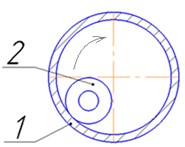
According to the vibration type, vibration exciters are divided into single-frequency and multi-frequency. An example of the excitation of polyfrequency oscillations is presented in Figure 1b, where the treadmill is run in by an unbalanced runner.
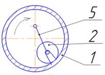
According to the type of excitation of vibrations, centrifugal vibration exciters are divided into unbalanced and planetary. In unbalanced, the inertial element (unbalance) is an unbalanced rotor with its shaft mounted in bearings (Fig. 1(a)). The generated driving force is transmitted to the exciter housing through bearings. The planetary vibration exciter inertial element (runner) is run on the treadmill of the body, making two movements: running and its own rotation, which are connected by a certain gear ratio. One of these movements is provided by the drive. The generated driving force is transmitted to the body through the treadmill.
Planetary vibration exciters are divided into lead and friction-planetary. In Fig. 1(b, c, d), diagrams of lead-planetary vibration exciters with external running are shown. The runner with its outer side surface is run in along the treadmill of the body with a leash, the rotation of which is reported by the shaft. The leash in the first case is forked, and in the second it is articulated. The driving exciters include planetary vibration exciters, in which the runner rolls along the treadmill of the body cavity under the action of the air supplied in the tangential direction. In the case of the use of unbalanced runners (Fig. 1(b)), two centrifugal forces of different frequencies arise.
One driving force develops as a result of rotation of the center of mass of the runner relative to the axis of rotation , and the second due to rotation of the roller relative to its axis . In this case, the movement of the runner can be represented as consisting of the translator together with the center of the runner and rotational relative to this center.
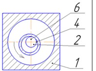
In friction-planetary vibration exciters, two principal schemes of their device are distinguished: with external and internal running-in. The friction-planetary vibration exciter with external break-in (Fig. 1(e)) has a slider, whose own rotation supports the engine through the shaft. The runner runs on the treadmill of the body. In the case of an internal run-in (Fig. 1(f)), a runner having an annular cross-section is rolled around the treadmill with its inner side surface, which is the side surface of a finger rigidly connected to the body. Own rotation of the slider informs the engine.
Fig. 1Flat diagrams of centrifugal vibration exciters with one inertial element: 1 – housing; 2 – inertial element; 3 – drive shaft; 4 – treadmill; 5 – drove; 6 – housing finger
a)
b)
c)
d)
e)
f)
In unbalanced vibration exciters, depending on the design requirements of the vibrator, determined by its technological purpose, shape, dimensions and weight, the shafts of the unbalanced mechanism can be made horizontal and vertical, coaxial, parallel or mutually perpendicular. A certain direction and synchronism of shaft rotation with unbalances is achieved, as a rule, by gears - cylindrical or conic. In relation to the longitudinal axis, vibration exciters can excite circular, longitudinal, rotational, longitudinal-rotational, transverse and helical vibrations, therefore, using synchronously rotating unbalances, you can create any single-frequency driving forces (forces, moments, their combinations). Each type of oscillation is used to perform a specific technological operation, for which it is most effective.
To transmit movement from the drive to the working body of the planetary vibration exciters, various types of carrier are used. The most common are towed vibroexciters (fork – Fig. 1(c, d); articulated – lever – Fig. 1(b) and friction – Fig. 1(d, f)).
According to the type of carrier installation in the vibration exciter case, there are symmetric (Fig. 1(c)) and asymmetric (Fig. 1(d)) vibration exciters. Asymmetric vibration exciters have increased dynamism and a high degree of unsteadiness of the working process due to the addition of the Coriolis forces of inertia to the centrifugal forces, which is achieved by the asymmetric shift of the axis of rotation along which the inertial runner moves.
The shape of the treadmill distinguishes planetary vibration exciters with a round, oval, elliptical track or track, the shape of which is described by higher-order curves.
According to the implementation type of the driving force, centrifugal vibration exciters can be directed and non-directed. In the latter case, the vibration exciter consists of two runners (eccentrics) rotating in different directions with the same angular velocity, arranged so that at each moment of time the horizontal components of the centrifugal forces are balanced, and the vertical components are summed. The directed action of the driving force is also inherent in asymmetric planetary vibration exciters.
The variety of vibration exciters used in the industry is very large, and they find more and more widespread use in all spheres of human activity, and people sometimes do not even think about their presence, for example, in cell phones, where they provide the well-known “vibration mode”.
But not all known vibration exciters are demanded by consumers, despite their well-known advantages.
The use of planetary vibration exciters on ice breaking, road and construction machines provides an effect on the processed material of significant driving force and at the same time increases the reliability of vibration exciters due to the action of the driving force of the inertial runner directly on the housing treadmill, bypassing the drive shaft.
The most effective in terms of driving force and polyfrequency effects on the material being processed is planetary vibration exciter with an offset center of carrier rotation (asymmetric planetary vibration exciter) [1-4], where the variable angular velocity of the inertial runner relative to the treadmill curvature center is provided by the eccentricity of the rotation axis of the carrier relative to this curvature center.
Due to the fact that the rotation center of the carrier of the vibration exciter is asymmetrically shifted in one direction, the maximum impulse of the driving force of the vibration exciter is shifted in the same direction, which can be 3-5 times larger than the pulse directed in the other direction [5-7].
The increase in the driving force in asymmetric planetary vibration exciters is achieved due to the additional effect on the inertial slider of the Coriolis inertia forces with a variable radius of its movement trajectory or a variable angular velocity.
However, Well-known designs of asymmetric planetary vibration exciters have a common drawback: the inertial slider slips along the surface of the treadmill under the influence of Coriolis forces and spontaneous torque within certain areas of the movement path. Slippage leads to a sharp, about an order of magnitude, increase in the energy intensity of the drive of the carrier and intensive heating of the inertial runners [8-11]. That is why all over the world there is still no widespread use of these vibration exciters.
Solving the slider's slippage problem could spread of this class of perspective vibration exciters, but nowadays almost no one of scientists has investigated the causes of inertial slider slipping on the treadmill surface and the vibration exciter working process, and the lack of understanding of these causes repels potential consumers from using asymmetric vibration exciters.
No one was engaged in the development of anti-skid devices for planetary vibration exciters, the use of which could several times increase the efficiency of these vibration exciters and reduce their energy consumption.
The novelty of the issue, the presence of contradictory information, the lack of a generalizing literature on this issue create great difficulties in the development of new vibration machines with planetary vibration exciters.
The authors of this article offer their original analysis of the causes and a previously unknown solution to this problem.
A. B. Yermilov, and then E. S. Temirbekov [5-7], considered the working process of an exciter with a powered drove, which provides the simplest kinematics of an inertial slider drive and transmits to the drive shaft of an exciter in its pure form a moment of resistance to the displacement of the inertial slider along the treadmill [4].
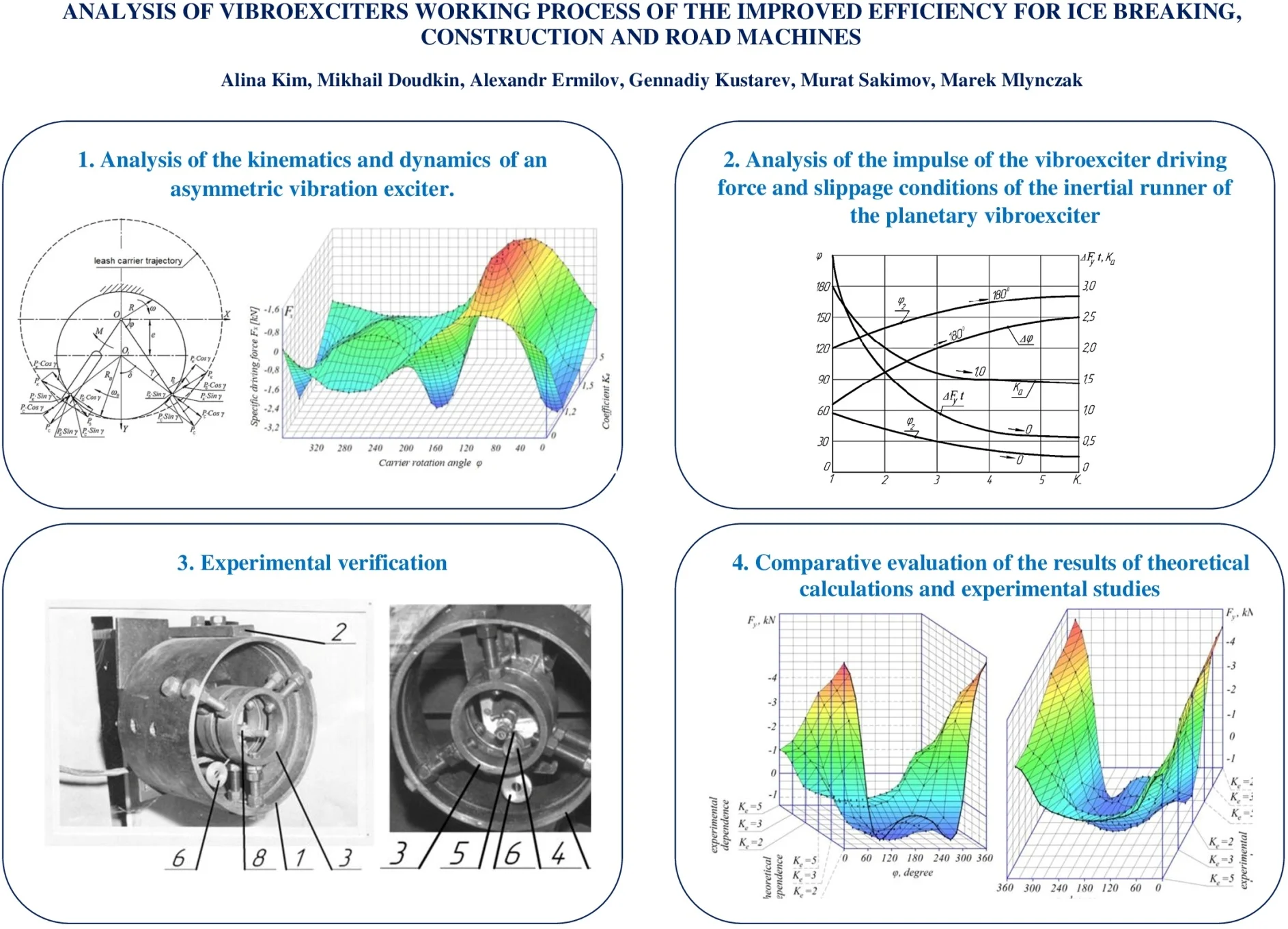
2. Analysis of the kinematics of an asymmetric vibration exciter
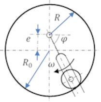
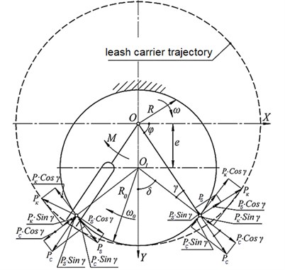
Fig. 2(a) shows a block diagram of an asymmetric planetary vibration exciter with a powered carrier, and Fig. 1(b) shows the calculated scheme of asymmetric planetary vibroexciter (APV) with a carrier of the leash type, where the inertial slider is represented as a material point.
The carrier rotation axis is shifted relative to the center of curvature of the treadmill to the eccentricity taking the radius of the treadmill , the following values are obtained from the geometric relationships by solving equations:
where –current rotation radius of the inertial slider relative to the rotation carrier axis; – current angle of inertia slider rotation ; – current rotation radius rotation of the inertial runner relative to the treadmill curvature center.
When solving Eq. (1) relative to the radius , the absolute value of the current radiuses obtained:
Due to the eccentricity, the inertial slider not only performs an asymmetric circular motion around the center , but also periodically moves along the radius of rotation with a radial velocity . Differentiating the equation of radius by the magnitude of the elementary current angle of rotation , the alternating radial velocity is obtained:
The magnitude of the current angle with regard to Eq. (2) is determined by the trigonometric dependencies:
The angle between the current radii of rotation and the curvature is determined by the dependence . Then , and . Using Eq. (4), the equation is:
It should be noted that at the points and , the function reverses sign, whereas the function remains positive over the entire range of variation of the angle .
Fig. 2The design scheme of the APV with a leash type carrier
3. Analysis of the dynamics of asymmetric vibration exciter
When the carrier rotates, the inertial slider is acted by the centrifugal force directed along a variable radius , the Coriolis force perpendicular to this radius and resistance force to movement of the tangent to the treadmill’s circumference, i.e. perpendicular to the radius . The proper weight of the inertial slider is neglected. Calculated values of centrifugal and Coriolis forces:
When and , the centrifugal force is , and the Coriolis force is 0, since at these characteristic points of the inertial runner’s trajectory the force changes its direction relative to the radius on the contrary. At , the force is directed in the direction of slider movement, at , the force counteracts the movement of the slider.
Since at the points and , the force effect sign and functions sign change simultaneously, the component always coincides in direction with the component .
From Eq. (6) and (7), taking into account Eq. (5), it follows that . Since the force directly depends on the function , it is always directed at an angle () to the vertical axis () of the exciter towards the eccentric displacement of the carrier rotation axis in the entire values range of the angle . The tangential forces and are mainly determined by the magnitude of the Coriolis force , therefore, in the interval , the indicated forces oppose the inertial motion of the slider (resistance moment 0), and in the interval contributes to its movement (0).
The force of resistance is a dissipative function and determined by the action of the force , normal to the surface of the treadmill:
where – rolling friction coefficient of the inertial slider along the treadmill. The component of the force , directed along the radius , is summed algebraically with the centrifugal force , therefore the additive force acting along the radius :
Accordingly, the additive tangential force , perpendicular to the radius , when its positive value coincides with the direction of rotation of the carrier at :
The additive tangential force , which characterizes the moment of resistance to the carrier’s rotation [8, 9]:
The added coefficient , depending on the angle , and after simplifying the Eq. (8-11) the equation is:
Moment of resistance to carrier rotation:
Since and angle 0, then
Projections of the driving force of the APV on the coordinate axis:
Using the expression,obtained from Eqs. (2) and (5) the equations in a dimensionless form:
where – coefficient of inverse specific eccentricity.
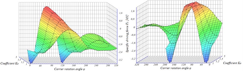
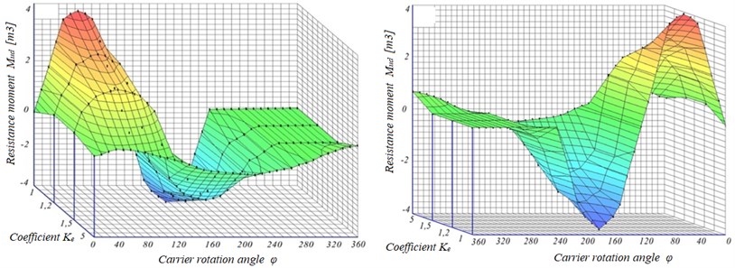
In Fig. 3, from two different points of view, the same graph of the specific force versus the carrier angle and the coefficient is shown. With an increase in eccentricity min, and oscillations acquire a poly-frequency nature. The intersection points of the graphs with the -axis approach the mean value of 90° with increasing eccentricity, and the extreme ordinates of the positive and negative branches of the graphs increase in absolute value.
This relationship is particularly important when calculating the working bodies of sealing or crushing machines and ice breakers [8-13], since it allows adjusting the force direction.
Fig. 3Dependence of projection of the specific driving force Fy on the ordinate axis on the carrier rotation angle φ of asymmetric exciter
For small values of (3), the negative branch of the graphs, which corresponds to the force action towards eccentric displacement of the carrier relative to the treadmill curvature center, acquires two extreme values that are symmetrical about the abscissa 90°. This is explained by the maximum effect of the Coriolis force on the lateral (relative to the axis ) sections of the treadmill. These extremes are larger than the extreme value of the positive graphs branch.
With an increase in the extremum of the positive graphs branch at 90°, the opposite value of the specific force at 270° decreases proportionally. For the theoretically admissible case 1, when the rotation axis of the carrier coincides with the circumference of the treadmill, the existence area of the graph will be . For , there is 0. Due to the polyfrequency nature of the oscillations, it is impossible to estimate their asymmetry by the extreme values ratio of the of the force , such an estimate can be made from the magnitude of the impulse force.
The graphs of the specific force (Fig. 4) are almost symmetric about the abscissa axis. The possibility of changing the magnitude and direction of the force is important in the design and calculation of flat wind robots and ice breakers [14, 15]. At 0, the dependency graph will be . With increasing eccentricity drove the area of graphs existence narrows to . When 90° and , there is 0.
The graphs of the specific moment of have a similar character (Fig. 5).
The average specific moment of the carrier exciter rotation is determined by the dependence obtained from the Eq. (16):
where – elementary angle of rotation.
Fig. 4Dependence of projection of the specific driving force on the abscissa axis on the carrier rotation angle of the vibration exciter
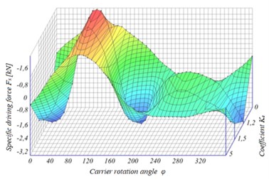
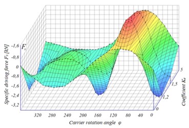
Fig. 5Dependence of the specific resistance moment to carrier rotation from the carrier rotation angle of the vibration exciter
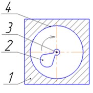
4. Analysis of the impulse of the vibroexciter driving force and slippage conditions of the inertial runner of the planetary vibroexciter
The impulse of the driving force projected on the axis is determined in general terms Eqs. (14):
The solution of this integral can be significantly simplified due to the fact that the last term of the integrand, containing a rolling friction coefficient 0.02, determines on average no more than 2-4 % of the specific driving force . Thus, considering the specific impulse of the driving force without taking into account the rolling resistance of the runner on the treadmill, the equation is:
For symmetric planetary vibroexciter with , the parameter .
A special case of solving the impulse force integral in the interval for different values of is complicated by the fact that integration limit of the positive and negative graph branches in Fig. 2 will change depending on . The integration limits are determined at , then , as a result .
The solution of the last expression allows finding the angle values corresponding to the limits of integration:
When 0 and , the and . When , the value is 55° and 125°.
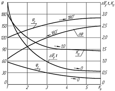
Fig. 6 shows a graph the integration change of upper and lower limits as a function of
The difference between the upper and lower limits of integration is the integration range of the positive branch , corresponding to the driving force action of the vibration exciter in the direction opposite to the eccentric shift of the carrier. With a decrease in , when , the value of the lower integration limit increases, and upper limit value and integration range decreases [11-15].
The particular integral solution of the driving force impulse according to the Eq. (18) within the integration and , defined by the Eq. (19), allows obtaining the impulse value directed towards the eccentric displacement of the carrier and in the opposite direction.
The difference between absolute values of these positive and negative impulses is the external impulse of the driving force and determines the external power characteristic of the asymmetric planetary vibroexciter [13-19].
Fig. 6 also shows the curve of the external impulse dependence ofthe driving force on the carrier eccentricity coefficient .
Dependence is a hyperbole, its analysis showed that it is fully adequate to the expression taking into account the percent error that occurs when the term determining the rolling resistance of the inertial runner is excluded from the Eq. (17).
The impulse asymmetry of the vibroexciter driving force relative to the abscissa axis is determined by the asymmetry coefficient:
The dependences graph of the asymmetry coefficient of the force versus impulse from the carrier eccentricity coefficient shown in Fig. 6, it is also a hyperbola. This graph with a fairly high degree of accuracy is approximated by the dependence:
When 0 and 0, the 1, i.e. harmonic oscillations law for a symmetric planetary vibration exciter.
When 1, we have the maximum value 3.
After determining the external pulse , it is possible to find the average integral value of the external directional force ,the vibration exciter has a static effect on the material being processed or the aggregates of the vibration road-building machine, for example, ice breaker, roller of the road roller or vibrating screen, with the full-speed dynamic effect: ; since , then . In absolute dimensional form:
Theoretical studies [16-20] and series of experiments showed that the main disadvantage of planetary vibration exciters with an offset rotation axis of the carrier is the inertial runner slipping along the surface of its treadmill. When the optimal variant of its rolling on the treadmill is violated, it leads to a sharp (about ten times) increase in the resistance moment to the rotation of the carrier and the energy intensity of the vibration exciter drive, however, with limited power and the drive motor, it leads to limit the frequency or disruption of [16-20]. The additional energy expended to overcome the sliding friction of the slider goes into heat and implemented to heat the slider and treadmill surface. Intensive heating and abrasive wear of the inertial slider and treadmill surface is observed. Accordingly, poor heat removal from the inertial runner leads to its thermal deformation and rapid destruction, which significantly reduces the reliability and durability of the vibration exciter, up to the limit of its [16-20].
Fig. 6Dependence of the lower φ1 and upper φ2integration limits, the integration range Δφ, the external impulse Fyt of the driving force and the asymmetry coefficient of the impulse ka from the carrier asymmetry factor ke
In a well-known article [16], the authors determined that the slider slips not across the entire trajectory of its movement, but only in certain areas, with an unfavorable combination of centrifugal and Coriolis forces on it, as well as additional inertia forces in the transient movement of the vibration exciter body.
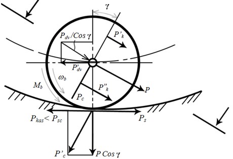
The alternating radial velocity of the inertial slider relative to the rotation center of the carrier determines the uneven action of the Coriolis forces on the slider parts that are distant at different distances from the specified center. It turns out that the distance from the rotation center of the slider carrier to the mass center of the external slider part is greater than the distance from the rotation center to the mass center of the internal half of the slider (Fig. 7). As a result, the slider acts on the entire circular trajectory of movement except for points of Coriolis torque, which in certain parts of the trajectory determines the slider's spontaneous slippage: its slipping within the arc of the trajectory () and skid in the range of . In addition, the additional torque ensures the discrepancy between the vector of the radial centrifugal force and the radius of the treadmill [20, 21].
To determine the true effectiveness of the asymmetric planetary vibration exciter and the development of constructive measures to prevent the inertial slider from slipping, the angular coordinates of the slip sites within the circular motion path of the slider [16-20] were previously determined.
The centrifugal angle of these areas increases with increasing eccentricity of the carrier and the specific rolling radius of the inertial slider, referred to the curvature radius of the ring treadmill.
According to the well-known studies [16-20], the maximum slippage probability of the inertial slider corresponds to the carrier positions 0 and , i.e. when the carrier is located perpendicular to the eccentricity of its rotation axis. For this maximum probability, the slippage mode occurs at the minimum values of the coefficient and eccentricity .
For example, for 0.4, the slider will occur within the arc 300° ... 60° or –60° ... 60°, and the slider’s skip – within the arc 120° ... 240°, i.e. the length of the left and right arc of the slider creep is 120°, and only within 120° of the central angle of the movement trajectory does the creeper move without slipping.
Fig. 7Design diagram of the movement conditions of the inertial runner of an asymmetric planetary vibration exciter
With the values and the slippage probability tends to zero, i.e. the angle corresponds to infinitely large values of . This is explained by the fact that in these positions of the carrier, the Coriolis force acting on the slider changes its sign and passes through zero, and the centrifugal force vector coincides with the slider rotation radius relative to the carrier rotation axis. Therefore, the tangential force is min (the minimum is determined only by the rolling resistance of the slider ), and the adhesion force is maximum , where is the centrifugal force.
For the accepted values of the parameters [16-20] , and the minimum value of the coefficient at which the slider slips, 0,196 at points 0 and , and for skip at least k is slightly higher (by 0.35 %) than for slider. Thus, the slider is more dangerous critical mode of its movement compared to the skid.
In any case, both to combat skid and to combat slippage, in known designs of asymmetric planetary vibration exciters, devices should be installed to prevent the inertia slide from slipping, and the use of which could provide a significant reduction in the energy intensity of the work, increase the efficiency and reliability of the vibration exciter. It is significant part to check this statement in practice.
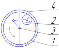
5. Experimental verification
An analysis of the considered theory of an asymmetric planetary vibration exciter indicates the need to improve its design, the main direction of which, along with the theoretical justification, is to evaluate the actual effectiveness of a device that prevents spontaneous slipping of an inertial runner when it moves along a treadmill under the action of Coriolis forces in practice.
To confirm the obtained dependencies and determine the true effectiveness of the pendulum anti-skid device, we will verify the adequacy of the proposed theoretical model experimentally.
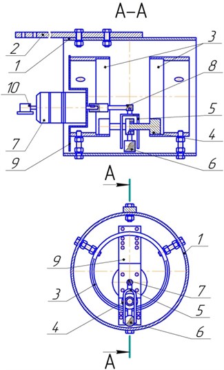
Description of the experimental setup. The object of research was a large-scale physical model of an asymmetric planetary vibration exciter with a pendulum anti-skid device, which is a pendulum 6 suspended from the axis of the inertia runner 4, the inertial mass of which was moved out of the treadmill 3 [16-20] (Figs. 8, 9, 10). The pendulum 6 provides a relatively large radius of integral center rotation of mass and the integral magnitude of the absolute mass compared with the radius of the treadmill 3 and at the same time the minimum mass and rotation radius of the inertial slider 4, which determine the effect of its spontaneous slip along the treadmill 3.
The drive shaft of the carrier 5 (Fig. 8) can be installed with an eccentricity about the center of curvature of the treadmill 3 by moving the panel 9 in a vertical plane. Engine 7 – direct current, power 1.0 kW, speed up to 6000 rpm.
The experimental stand also included a remote control system for the operation of the vibration exciter and equipment for recording the loading parameters of the vibration exciter.
The geometric sum of the normal and tangential reactions of all forces on the treadmill 3 provides the driving force of the vibration exciter, the fixation of the vertical component of which was carried out using a strain gauge link glued to strain gauge beam 2 mounted on a support.
When the strain-gauge bend 2 was bending, the signal from the strain-gauge was processed and recorded with special ZetLab equipment and displayed on a computer screen.
Also, during the experiment, the values of the voltage and current applied to the motor exciter were monitored and recorded.
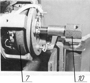
The rotation frequency of the motor shaft (drive drove) was measured by a frequency meter, to the input of which a signal was sent from a magnetic induction sensor mounted on the free end of the drive shaft (Fig. 9).
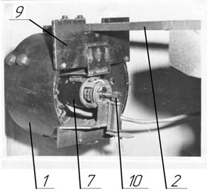
Fig. 8The design of the experimental stand of the planetary vibration exciter: 1 – body; 2 – strain girder; 3 – treadmill; 4 – inertial slider; 5 – drove; 6 – pendulum anti-skid device; 7 – the engine; 8 – drive shaft sleeve; 9 – engine mounting panel
During the experiment, the model was an asymmetrical planetary vibration exciter (Fig. 9) with parameters: treadmill radius 50 mm; the radius of the runners 15 mm; the runner mass is 79.73 g and 65.97 g.
In the experiment, pendulum anti-skid devices of the same geometric dimensions, but of different mass were used: 14.73 g; 37.21 g; 59.69 g, with . In other cases, . Weight drove 30.07 g. Pendulum length 50 mm.
Separated by an axial gap, the two sections of the treadmill are mounted inside the cylindrical body with mounting bolts arranged at an angle of 120° relative to each other. In the axial gap a pendulum with a load device anti-skid inertial slider is placed.
The installation on the shaft of the drive motor, magnetic induction sensor used to measure the angular velocity of the exciter driver, fixed by a frequency meter is shown in Figs. 9, 10.
Fig. 9General view of the vibration exciter on the experimental stand
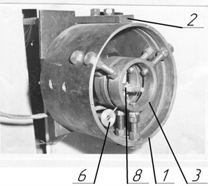
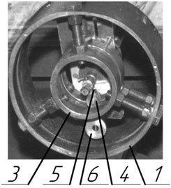
Fig. 10Installation of a vibration exciter carrier on the stand of the magnetic induction speed sensor
The instant traces of the spatial position of the pendulum anti-skid device, showing the angular displacements of the pendulum relative to its radial position under the action of centrifugal and Coriolis forces, were recorded using a stroboscope.
5.1. Analysis of the experiments
As a result of the experiment to determine the effect of the carrier eccentricity and the mass of the pendulum anti-skid device on the target function – the driving force of the vibration exciter, the dependencies of the driving force were obtained on the current rotation angle of the carrier within 0 360°.
Fig. 10 shows the experimental projection dependence of the specific driving force on the ordinate axis on the angle of rotation of the carrier with the eccentricity of the latter, 1.67 cm, which corresponds to the value of 3.
In the graph, the theoretical dependence of the specific driving force as a function of the angle for a runner without a pendulum anti-skid device is similarly dotted.
Analysis of the graphs shows that an increase in the carrier’s eccentricity leads to a significant distortion of the sinusoidal nature of the dependence of the specific driving force as an angle function . With a slight increase in the amplitude of at 90°, directed in the direction opposite to the eccentricity of the carrier, the value of the amplitude directed to the other side (in the eccentricity direction of the carrier relative to the curvature center of the treadmill) increases significantly, just as the magnitude of the force pulse increases and the mean integral force in time .
Fig. 11Experimental projection dependence of the specific driving force on the ordinate axis on the rotation angle of the carrier driver and different mass of the pendulum at Ke= 3 and Mb1= 65.71 g
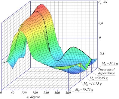
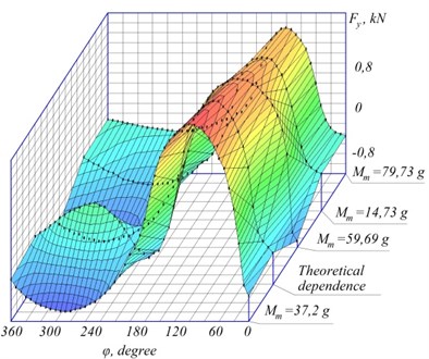
Fig. 11 shows the experimental dependences of the change in the relative magnitude of the driving force as a function of the angle for the minimum value of the eccentricity of the carrier, equal to 1 cm, which corresponds to the value 5. On the same graph, the dotted line shows the theoretical dependence of the specific driving force as functions of angle obtained by the previously derived formulas for an asymmetric planetary vibration exciter with an inertial slider without a pendulum anti-skid device. Dependence is sinusoidal. The maximum amplitude of the specific driving force corresponds to the angle 90° and is directed in the direction opposite to the eccentricity of the carrier relative to the center of curvature of the treadmill. The maximum value of the integral impulse of the specific driving force , as the difference of the areas and located between the positive and negative branches of the sinusoidal axis of the abscissa at 0, corresponds to the value 270°, i.e. the position of the carrier, coinciding with the direction of its eccentricity relative to the center of curvature of the treadmill.
Thus, the magnitudes of the maximum amplitude and maximum impulse of the specific driving force are opposite to each other in direction. Therefore, when compacting the material using an asymmetric planetary vibration exciter, the eccentricity of the carrier relative to the center of the treadmill curvature of the vibration exciter should be oriented towards the surface of the material being compacted.
Due to the small eccentricity of the carrier, the additional inertial mass of the pendulum anti-skid device practically does not affect the value of the specific driving force .
The theoretical values of the specific driving force as a function of the angle slightly exceed the amplitude of the experimentally recorded value due to the fact that the physical model inevitably has dissipative energy losses due to the sliding friction of the axis of the runner relative to the powered carrier, etc. In general, this reduces the absolute values of the specific driving force with unchanged other parameters and modes of operation of the vibration exciter.
An increase in the mass of the pendulum leads to a corresponding increase in the amplitude of the specific driving force , which is explained, in addition to the general increase in the inertial moment of the planetary system, by an additional decrease in the inertial slider slipping zones and energy loss to its spontaneous slippage , which is equivalent to an increase in the specific slippage force with the same parameters of the workflow (based on the unchanged power balance of the process of planetary motion of the inertial runner ).
Fig. 12Experimental projection dependence of the specific driving force on the ordinate axis on rotation angle of vibrofibers driver and different mass of the pendulum with Ke= 5 and Mb1= 65.71 g
For the conditions of the experiment, the rational mass of the pendulum is 50-60 % of the mass of the inertial runner.
The data obtained during the experiments were checked for convergence with the results of theoretical calculations [7-12]. The magnitude of the discrepancy between the theoretical and experimental values averaged 19-27 % for a runner without anti-skid means and 7-10 % for a runner with a pendulum. The greatest scatter of results is observed in the intervals ( ± 20°) and (2 ± 20°). The increase in the eccentricity e or the radius of the slider contributed to an increase in the discrepancy between the theoretical and experimental values due to a corresponding decrease in the latter in these cases.
The use of a pendulum anti-skid device gave the greatest convergence with theoretical dependencies. However, an increase in the mass of the pendulum does not always lead to a corresponding increase in the driving force. There is a pattern of mass influence of the pendulum on the driving force with changes in parameters of the vibration exciter such as eccentricity , the rotation frequency introduced and the radius of the runner . From the graphs in Figs. 12 and 13 it can be seen that for different values of eccentricity the various masses of the pendulum give the greatest convergence. Moreover, the increase in eccentricity gives greater convergence with increasing mass of the pendulum and vice versa. With an excessive increase in the mass of the pendulum and a small eccentricity, there is an intense heating of the surface of the inertial runner and treadmill due to the growth of resistance to the movement of the inertial runner [13-21].
The second stage of the experiment is based on a second-order orthogonal plan (two factors on three levels) with the following variable parameters – carrier rotation frequency and mass of the pendulum anti-skid device , while maintaining the geometric parameters of the device and the mass of the inertial slider for different eccentricity of the carrier.
To identify the most optimal working conditions of the vibration exciter, the second stage of the experiment was carried out at different eccentricities of the carrier ( 1 cm; 1.67 cm; 2.5 cm). The magnitude of the eccentricity changed after the completion of the experiment with the previous eccentricity, i.e. in the process of research, the values of and changed for some specific experience for each experiment, the values of eccentricity . The required number of repeated experiments in experimental studies was determined after preliminary measurements according to known methods.
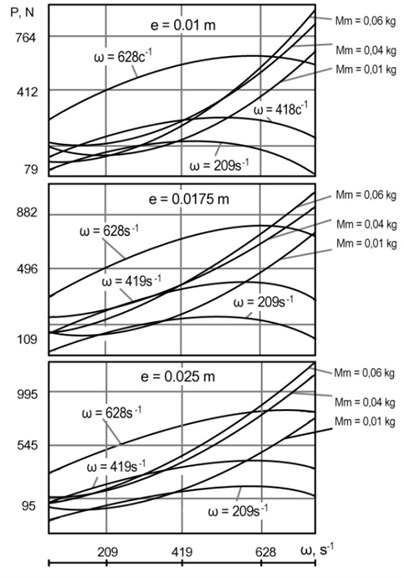
During the third stage of the experiment, the angular velocity of the carrier , the mass of the pendulum anti-skid device and the eccentricity of the carrier were taken as independent parameters. The objective function – the driving force of the vibration exciter, is directed along the axis of its symmetry towards the eccentric displacement of the carrier.
The results of the third stage of the experiment are interpreted by the graphs shown in Fig. 13.
The graphs of the results of the third stage of the experiment fully confirm the physical adequacy of the dependencies obtained during the second stage of the experiments. With an increase in the eccentricity of the carrier from 1 cm to 2.5 cm, the magnitude of the driving force , as a function of the eccentricity of the carrier, is traceable both with the variation of the angular velocity of the carrier and with the variation of the mass of the pendulum anti-skid device .
Fig. 13Experimental dependence of the driving force of an asymmetric planetary vibration exciter on the angular velocity of the carrier ω and the mass of pendulum anti-skid device for different values of the carrier eccentricity
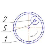
6. Comparative evaluation of the results of theoretical calculations and experimental studies of asymmetric planetary vibration exciter with pendulum anti-skid device
An analysis of experimental data clearly shows an increase in driving force of the vibration exciter with an increase in the carrier eccentricity relative to the curvature center of the treadmill and integral inertial mass (runner, pendulum and load) making a planetary motion (Fig. 14). An increase in eccentricity from 0 to 2.5 cm provides an increase in the absolute value of the driving force towards the eccentric displacement of the carrier relative to the center of curvature of the treadmill by an average of 87 %, with a greater increase in the driving force with increasing eccentricity corresponding to the maximum integral inertial mass of the runner and device anti-skid. The excess of the theoretical values of the force over the experimental ones is explained by the influence of dissipative losses, which are not taken into account in the theoretical formula.
Analysis shows that with increasing mass of the pendulum to values close to the mass of the inertial runner, the greatest convergence of theoretical and experimental dependencies resulted in a corresponding increase in the eccentricity of the drove relative to the curvature center of the treadmill. This can be explained by excessive pressing of the inertial slider to the treadmill with a small eccentricity, when slippage is not so significant, and additional pressing of the slider to the treadmill with a large mass of the pendulum anti-skid device gives only an increase in the resistance to slider movement.
As the eccentricity increases, the slider slips along the treadmill and additional pressing of the slider under the action of inertial forces acting on the pendulum anti-skid device begins to perform useful work, pressing the slider against treadmill and preventing the rolling friction of the slider from sliding to slide over the treadmill.
The divergence increase of the impulse values of the driving force in the direction opposite to the carrier eccentricity can be explained by the dissipative energy losses caused by the sliding friction of the slider relative to the pedestal carrier, treadmill and pendulum anti-skid device.
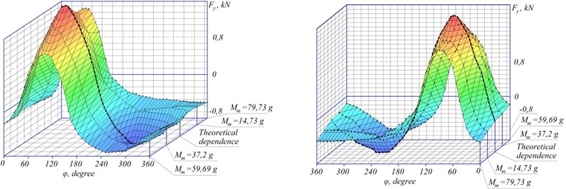
Analysis of the graphs shows that with the same specific eccentricity 3, an increase in the mass of the pendulum anti-skid device, respectively, increases the impulse value of the specific driving force and the average integral value of the force .
Moreover, the discrepancy between the theoretical and experimental dependences for the impulse of the specific driving force increases with increasing mass of the pendulum anti-skid device, and for the amplitude directed towards the eccentricity of the carrier relative to the center of curvature of the treadmill the convergence is almost the same and the difference is 6-10 %.
If the theoretical dependence within 90° 270° has a saddle-shaped amplitude reduction, as a result of the predominantly tangential orientation of the action on the inertial slider of Coriolis forces in the specified angle range, there is practically no saddle on the experimental curve.
The curve passes through the average value of the theoretical curve amplitudes with a similar mass of the inertial runner and pendulum anti-skid device, having a pronounced bulge within 90° 270°, which can be explained by measurement errors and strain gauges that smoothed the saddle-shaped change in the specific driving force.
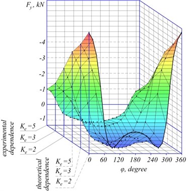
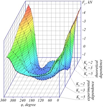
Fig. 14 shows the dependence of the theoretical and experimental projections of the specific driving force of an asymmetric planetary vibration exciter on the ordinate axis on the rotation carrier angle for different values of the specific eccentricity with a constant ratio of the mass of the pendulum device to the mass of the inertial slider 0.749.
Fig. 14Dependence of the projection of the specific driving force of an asymmetric planetary exciter on ordinate axis on the rotation carrier angle
7. Conclusions
1. In asymmetric planetary vibration exciters, the driving force is transmitted from the inertial sliders directly to the treadmill, bypassing the bearings of the carrier shaft, which increases their reliability and durability. Due to the additional impact on the inertial slider of Coriolis forces, the directed driving force of the vibration exciter significantly increases (1.5-2 times) with the same dimensions and mass of the vibration exciter relative to the center of curvature of the treadmill.
2. The Coriolis force acting on an asymmetric planetary vibration exciter provides a spontaneous torque of the slider causing slippage (slipping or skidding) of the slider on the treadmill, which is a negative factor leading to a sharp increase in energy intensity and heat density of the vibration exciter. The minimum value of the treadmill eccentricity ratio to the radius, at which the slider slips, is 0,196 () at the points 0 and of the movement trajectory, and at least several times higher (by 0.35 %) than for slip slider. Thus, the slider is more dangerous critical mode of its movement compared to the skid.
3. The pendulum anti-skid device proposed as a result of research provides an increase in the specific driving force of the vibration exciter by 20-60 % for a mass of the pendulum of 40-60 % of the runner mass by increasing the total Coriolis force acting on the inertia slider and pendulum, and reducing the inertial runner slippage on a treadmill, i.e. reduce the dissipative dissipation of the part of the drive energy of the exciter.
4. The driving force of an asymmetric planetary vibration exciter parabolicly depends on the mass of the pendulum anti-skid device with a clearly defined extremum. This allows to determine the nature of changes in the magnitude of the driving force as a function of the angular velocity of the carrier at optimal mass values of the pendulum anti-skid device and to make an informed choice of the specified mass when designing asymmetric planetary vibration exciters.
5. Changing the slider weight or rotation frequency of the carrier with a constant design of the vibration exciter does not affect the value of the specific driving force. If the mass ratio of the runner and pendulum mass change in the integral mass, reducing the weight of the runner and increasing the pendulum mass, then the specific driving force increases by 2-3 times, depending on the treadmill radius.
6. A decrease in the runner weight and an increase in the pendulum mass with their constant sum reduces the rolling circumference radius of the runner, the central angle of the slip zones and the total energy intensity, which determines the feasibility of using pendulum anti-skid devices on an asymmetric planetary vibration exciter.
7. For an asymmetric planetary vibration exciter with a pendulum anti-skid device, the discrepancy between theoretical calculations and experimental data is 6-10 % due to a more deterministic process while decreasing the relative length of inertial runner slipping zones and the number of random factors corresponding to this spontaneous slippage under the influence of Coriolis force.
8. The asymmetrical planetary vibration exciter with the multi-frequency law of dynamic driving force ensures the action of external static force, the impulse for one revolution vibration exciter carrier proportional to the eccentricity of the carrier relative to the curvature center of the treadmill and directed towards this eccentric carrier displacement, which is explained by the action of Coriolis forces on the inertial runner. The absolute value of the external static exciter force does not depend on the radius of the treadmill.
9. An asymmetrical vibration exciter can be used practically in drives of working tools of ice breakers or road machines where directional action of the driving force is required, the magnitude of impulse, when acting towards the eccentric displacement of the carrier, is almost an order of magnitude greater than the impulse acting in the opposite direction, which will undoubtedly increase efficiency their work.
References
-
Stryczek J., Banaś M., Krawczyk J., Marciniak L., Stryczek P. The fluid power elements and systems made of plastics. Procedia Engineering, Vol. 176, 2017, p. 600-609.
-
Giel R., Młyńczak M., Plewa M. Evaluation method of the waste processing system operation. Risk, Reliability and Safety: Innovating Theory and Practice. Proceedings of the 26th European Safety and Reliability Conference, 2016.
-
Bergander M., Vakhguelt A., Kapayeva S., Khairaliyev S. Ultrasonic evaluation of the combined effect of corrosion and overheating in grade 20 steel water-wall boiler tubes. INSIGHT, Vol. 59, 12, p. 637-643.
-
Andrzejczak K., Młyńczak M., Selech J. Computerization of operation process in municipal transport. Advances in Intelligent Systems and Computing, Vol. 761, 2019, p. 13-22.
-
Ermilov A. B. Theoretical analysis of the operation of an asymmetric planetary vibration exciter with a pendulum anti-skid device. VTsNIITECHstroymash deposited, Vol. 24, 1991, p. 91.
-
Dzholdasbekov S. U., Temirbekov Y. S. Shock-free race track of road roller vibration. exciters Proceedings of the World Congress on Engineering, London, Vol. 3, 2011.
-
Fedotov A. I., Młyńczak M. Analytical identification of parameters influencing measurement quality using flat brake tester. Advances in Intelligent Systems and Computing, Vol. 470, 2016, p. 147-155.
-
Usubamatov R., Zain Z. M., Sin T. C., Kapayeva S. Optimization of multi-tool machining processes with simultaneous action. The International Journal of Advanced Manufacturing Technology, Vol. 82, Issues 5-8, 2016, p. 1227-1239.
-
Plewa M.Giel R., Młyńczak M. Logistic support model for the sorting process of selectively collected municipal waste. Advances in Intelligent Systems and Computing, Vol. 365, 2015, p. 369-380.
-
Doudkin M., Apshikur B., Kim A., Ipalakov T., Asangaliyev E., Mlynczak M. Development of an installation for shear ground testing in the railway track construction. News of the National Academy of Sciences of the Republic of Kazakhstan, Series of Geology and Technical Sciences, Vol. 6, Issue 438, 2019, p. 22-35.
-
Scerbo L. J. Positive Drive Vibratory Mechanism. Patent USA No. 3868859, 1975, p. 74-61.
-
Doudkin M., Apshikur B., Kim A., Ipalakov T., Asangaliyev E., Mlynczak M., Tungushbayeva Z. Development of mathematical models describing the processes occurring in the railway track construction as a whole, or in the work of its individual elements. News of the National Academy of Sciences of the Republic of Kazakhstan, Series of Geology and Technical Sciences, Vol. 5, Issue 437, 2019, p. 6-15.
-
Brau F. W. Vibration Mechanism. Patent USA No. 3486387, 1969, p. 74-61.
-
Doudkin M., Kim A., Guryanov G., Mlynczak M., Eleukenov M., Bugaev A., Rogovsky V. Process modeling and experimental verification of the conditions of ice coverage destruction of automobile roads. Journal of Mechanical Engineering Research and Developments (JMERD), Vol. 42, Issue 4, 2019, p. 1-8.
-
Sakimov M. A., et al. Finding allowable deformation of the road roller shell with variable curvature. News of the National Academy of Sciences of the Republic of Kazakhstan, Series of Geology and Technical Sciences, Vol. 3, Issue 429, 2018, p. 197-207.
-
Gabdyssalyk R., et al. Study of the structure and properties of the metal of 10Cr17Ni8Si5Mn2Tigrade during cladding in a protective atmosphere. News of the National Academy of Sciences of the Republic of Kazakhstan, Series of Geology and Technical Sciences, Vol. 2, Issue 428, 2018, p. 95-103.
-
Ermilov A. B., Doudkin M. V. Determination of the boundary conditions for the slip of the inertial slider of an asymmetric planetary vibration exciter. VTsNIITEstroymash, 1988, p. 86-88.
-
Temirbekov E. S., et al. Combined trajectory of continuous curvature. advances in Italian mechanism science. Proceedings of the Second International Conference of IFToMM Italy, Mechanisms and Machine Science, Vol. 68, 2019, p. 12-19.
-
Bergander M., Vakhguelt F., Kapayeva S., Khairaliyev S. Remaining life assessment for boiler tubes affected by combined effect of wall thinning and overheating. Journal of Vibroengineering, Vol. 19, Issue 8, 2017, p. 5892-5907.
-
Doudkin M., Kim A., Kim V., Mlynczak M., Kustarev G. Computer modeling application for analysis of stress-strain state of vibroscreen feed elements by finite elements method. Communications in Computer and Information Science, Vol. 998, 2019, p. 82-96.
-
Bostanov B. O., et al. Mechanics-mathematical model of conjugation of a part of a trajectory with conditions of continuity, touch and smoothness. Communications in Computer and Information Science, Vol. 998, 2019, p. 71-81.
-
Doudkin M., Kim A., Kim V. Application of FEM Method for Modeling and Strength Analysis of Feed Elements of Vibroscreen. Lecture notes in mechanical engineering, 2019, p. 155-162.
-
Kombayev K. K., Doudkin M. V., Kim A. I., Mlynczak M., Rakhadilov B. K. Surface hardening of the aluminum alloys AL3 by electrolytic-plasma treatment. News of the National Academy of Sciences of the Republic of Kazakhstan Series of Geology and Technical Sciences, Vol. 4, Issue 436, 2019, p. 222-229.
Cited by
About this article

Alina Kim – theoretical investigation of asymmetric vibration exciters, analysis of the kinematics of an asymmetric vibration exciter, development of mathematical model of the new exciter, 3D graphs. Mikhail Doudkin – analysis of the dynamics of asymmetric vibration exciter (dependence of the specific resistance moment to carrier rotation from the carrier rotation angle of the vibration excite, dependence of projection of the specific driving force on the abscissa axis on the carrier rotation angle of the vibration exciter). Experimental studies of asymmetric planetary vibration exciter, comparative analysis of the experimental results. Introduction and conclusion parts of the article. Alexandr Ermilov – development of the design scheme of the APV with a leash type carrier. Theoretical investigation of asymmetric vibration exciters, analysis of the kinematics of an asymmetric vibration exciter. Gennadiy Kustarev – analysis of the impulse of the vibroexciter driving force and slippage conditions of the inertial runner of the planetary vibroexciter, analysis of the dynamics of asymmetric vibration exciter. Development of the design scheme of the APV with a leash type carrier. Murat Sakimov – development of the experimental setup, experimental studies of the asymmetric vibration exciter, analysis of the experimental results. Marek Mlynczak – analysis of the results of the third stage of the experiment, description of experimental dependence of the driving force of an asymmetric planetary vibration exciter on the angular velocity of the carrier. Comparative evaluation of the results of theoretical calculations and experimental studies of asymmetric planetary vibration exciter with pendulum anti-skid device.
