Abstract
Aiming at the vibration defects of star compressor, simulation and experiment are carried out to investigate the compressor. By drilling holes in the valve stem, the pressure changes of each cylinder are measured without damaging the cylinder block. The dynamic model of crank-connecting rod mechanism is established. After the measured cylinder pressure loaded on the dynamic model, the force acting on the main motion pair is obtained. The finite element model of the compressor is established for the first time, the force of the motion pair is loaded on the finite element model by MPC coupling method, and the vibration acceleration of the machine base is tested. The result shows that the main modal shapes between 50-150 Hz are body deformation, modal shapes between 150-200 Hz are base deformation, the simulation acceleration of the base is higher than that of the experiment, and the main working frequency and frequency doubling can correspond. The conclusions provide reference for vibration isolation design of star compressor.
Highlights
- By drilling holes in the valve stem, the pressure changes of each cylinder are measured without damaging the cylinder block.
- The dynamic model of the crank-connecting rod mechanism and the finite element model of the compressor is established for the first time.
- For the compressor, the main modal shapes between 50-150 Hz are body deformation, modal shapes between 150-200 Hz are base deformation.
1. Introduction
Reciprocating compressor is widely used in petroleum, chemical industry, shipping and other industries because of its advantages such as wide range of output pressure, high exhaust pressure and mature manufacturing technology. The cylinder arrangement of multi-stage reciprocating compressor includes L-type (in-line), V-type, W-type and star-type. Star-type arrangement can balance its inertia force to a certain extent, which keeps the total vibration level of compressor relatively low. However, with the development of the special ships performance, higher requirements are put forward for the vibration standard of compressor, and with the increase of exhaust pressure and displacement, the vibration problem of star compressor turns out to be more prominent. In the process of compressor design, if the vibration performance can be predicted by computer simulation, the development cycle of compressor can be shortened and the cost can be reduced [1, 2].
The finite element analysis method is widely used to predict the vibration of compressor. However, the boundary conditions are difficult to be consistent with the actual situation. The characteristic of internal excitation force are difficult to acquire, besides, the error of finite element analysis itself, the relevant calculation results can only predict some trends of vibration. Ref. [3] simulates the vibration characteristics of V-type compressor by finite element method. Since the gas pressure is calculated according to theory, the airflow pulsation caused by valve switch is not considered, and the simulation model is simplified to some extent, so the simulation results and experiment data have certain errors. Ref. [4] predicts the vibration and noise response of large reciprocating compressor, but the experiment is only compared with the displacement response, the vibration part of simulation is not fully verified by of the experiment. Ref. [5] analyzes the influence of clearance on vibration response for compressor and concludes that the simulation vibration sensitive test points are consistent with the experiment, even though the outer box of compressor is simplified regularly. Although the finite element simulation cannot ensure that the actual situation is completely consistent with the actual situation, but it can be assisted with experimental test, as close as possible to the actual working conditions of the real compressor [6, 7].
This paper includes five sections. Section 1 introduces the basic structure of star compressor and establishes the dynamic model of crank-connecting rod mechanism. In Section 2, the measured cylinder pressure data is obtained by drilling holes in the valve stem. In Section 3, the force of the pressed air is loaded on the mass center of the piston for the dynamic modeling of crank-connecting mechanism, and the force of the motion pair is obtained. In Section 4, the force of the motion pair is loaded on the finite element model by MPC coupling, and the vibration acceleration of the corresponding measured points is obtained. Then the simulated acceleration and the measured acceleration of the corresponding measuring point are compared in Section 5. The conclusion is drawn in Section 6.
2. Structural of star compressor
2.1. Structural characteristic
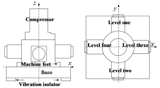
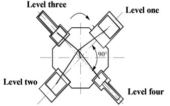
The common star compressor are three-star or four-star type. Their common characteristic is that there is only one crank. The piston is distributed around the vertical crankshaft. The original motor is integrated, which owns high speed and good operation economy. The compressor studied in this paper adopts a single-acting four-stage compression structure. Four connecting rods are arranged side by side on the vertical crankshaft. The piston is radially distributed around the crankshaft every 90 degree. Fig. 1 shows the schematic diagram of the structure. The arrangement greatly shorts the length of the crankshaft, which improves the natural frequency of the crankshaft to a certain extent, and makes the structure of the whole machine more compact. Inertia force of the piston gets a better balance by two pairs of connecting rods locating at both ends of the crank symmetrically [8].
Fig. 1Schematic diagram of star compressor structure
2.2. Dynamic modeling of crank-connecting mechanism
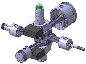
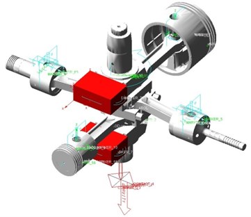
A compressor consists of many parts. In order to facilitate dynamic modeling and calculation, the piston assembly, connecting rod assembly and crankshaft assembly are simplified into three-dimensional assembly model by four pistons, four connecting rods and one crankshaft by Boolean operation. The three-dimensional model is saved as *.x_t file and imported into ADAMS/View. The piston and connecting rod, connecting rod and crankshaft, crankshaft and ground are connected by rotating pair, and the piston and ground are connected by moving pair. The rotation drive speed 1480 r/min is loaded on the rotational pair of crankshaft and ground. At the same time, gravity is applied to the whole system. Then the dynamic model of crank-connecting rod mechanism is obtained, as it is shown in Fig. 2. The mass of piston assembly is 4 kg, the mass of connecting rod assembly is 5 kg, the mass of crankshaft is 30 kg, and the mass of balance weight is 5.83 kg. Because the influence of flexible crankshaft on the moving pair is not so great compared with rigid crankshaft, the dynamic analysis of rigid crankshaft is adopted in this paper [9].
Fig. 2Dynamic model of crank-connecting rod mechanism
2.3. Modal analysis
The differential equation of crankshaft vibration is described as [4]:
where , and are the mass matrix, damping matrix and stiffness matrix respectively, , and are the acceleration matrix vector, velocity matrix vector and displacement matrix vector respectively, is the load matrix vector.
The influence of damping on modal shapes and modal frequencies can be neglected. In a free vibration status, we ignore the external force in Eq.1, namely . So, the Eq. (1) can be written as:
When the structure at free vibration status is under natural frequency, substituting , we can get the basic equation of the modal analysis without damping as:
When the equation has nonzero solution, the condition must be satisfied. Characteristic root is the natural frequency of the structure, characteristic vector is the corresponding mode. Because of the irregular shape of the crankshaft, it is difficult to solve the differential equation. Therefore, the finite element method is used to solve the problem, and the experiment is used to verify it.
3. Cylinder pressure test
Cylinder pressure is an important parameter reflecting the working state of compressors. Generally, compressors are equipped with pressure gauges, but the gauges only get a rough pressure of compressor cylinder under stable working conditions, which is far from scientific research. Many scholars adopt the method of theoretical derivation to get the pressure of compressor cylinder and take it as an exciting force to analyze the response of compressor. Since the effect of valve dynamic performance on gas pulsation is not taken into account, there is a certain error between the derivate result and the actual situation [10].
Fig. 3Cylinder dill and pressure test
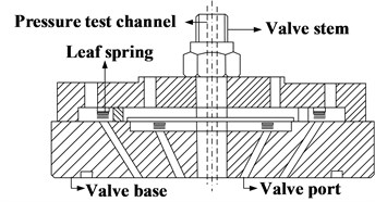
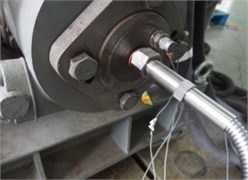
Fig. 4Cylinder pressure variation curve at 25 MPa
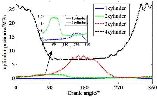
The compressor exhaust pressure is higher than the combustion explosion pressure within the common diesel engine, and the temperature of compressed air is high. To measure the pressure of compressor cylinder, the first thing is to ensure the sealing, second is the high temperature resistance of the sensor. In order to acquire the actual cylinder pressure of each cylinder without damaging the cylinder structure, the method of valve stem drilling is adopted. Each cylinder cover has a valve. The valve stem is used to fix the valve cover and valve base. The hole is drilled in the center of valve stem, as is shown in Fig. 3, transducer is installed on the cylinder cover. By measure the pressure of the compressor cylinder on 25 MPa working condition, the pressure curves of each cylinder are obtained in Fig. 4. From the figure, it can be seen that there is obvious negative pressure in the first stage cylinder pressure, and the third and fourth stage cylinders have obvious effect on the increase of exhaust pressure. Because the diameter of three and four cylinders is small, in order to ensure the stability of the compression process, the guide sleeve is designed at the bottom of the piston.
4. Simulation of motion pair excitation force
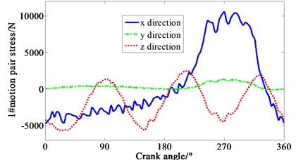
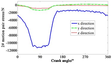
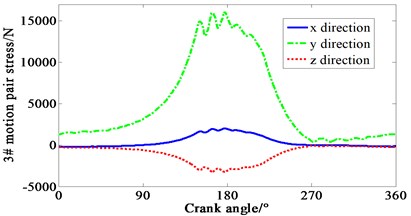
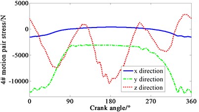
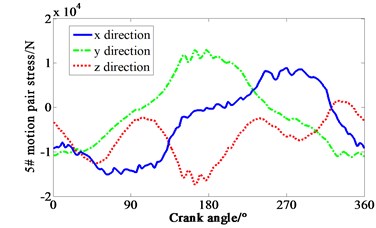
Multiplied by the area of piston head, cylinder pressure shown in Fig. 4 is transformed to force. Loaded the force on each piston mass center of crank-connecting rod mechanism. Speed drive is loaded on the dynamic model of the mechanism at the same time. The curve of force varied with crank angle is obtained in Fig. 5. 1-4# motion pair are four joints between piston and connecting rod respectively. 5# motion pair is the joint between shaft and main bearing. It can be seen that the -direction forces of the 1# and 4# motion pair are relatively complex, mainly due to the negative pressure in the suction process of cylinder one, and the pressure fluctuation caused by the four cylinders’ valve is relatively large. It means that both the inlet and outlet of the compressor makes the gas pressure irregular.
Fig. 5Curve of force variation with crank angle
5. Simulation and experiment of vibration characteristic
5.1. Finite element modeling
Since the actual compressor block structure is complex, some structures need to be simplified in the process of establishing the finite element model. The simplification of solid three-dimensional model mainly includes the following steps. Firstly, remove structural external attachments, such as pipelines, condensers and oil-water separators, and adding them as a concentrated mass to the nodal located near the corresponding installation holes. Secondly, remove crank-connecting rod mechanism. The force acting on the body is loaded by the dynamic analysis of the crank and connecting rod. Thirdly, delete structural details. Remove oil holes, most bolt holes and air valves which have little influence on the whole structure. Fourthly, the structure is simplified. The motor is replaced by shell pulled out from cylinder, which only guarantees the mass is equal. The crankcase cover plate and the crankcase, the motor and the crankcase, the crankcase and the base are all integrated by boolean operation [11].
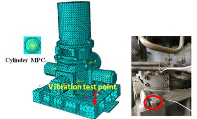
The three-dimensional model is imported into Abaqus, and the tetrahedron C3D10 element is used for meshing. In order to balance the calculation accuracy and time, the number of elements is 81555 and the number of nodes is 140691. The coupling between the motion pair and the cylinder sleeve is carried out by MPC. The four isolators between the base and the ground are replaced by springs with corresponding stiffness 1.52e6 N/m. The finite element model is obtained in Fig. 6. The body is made of material QT450, the base is made of QT235, and the spring between the body and the raft seat is replaced by 1e8N/m, which is closed to the stiffness of the material in order of magnitude.
Fig. 6Compressor finite element model and measuring point location
5.2. Result analysis
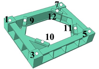
The experimental equipment are LMS acquisition card, notebook computer, and DYTRAN 3055B2T acceleration transducer. The location of acceleration point is shown in Fig. 7. Sampling frequency is set as 25.6 KHz.
Fig. 7Compressor finite element model and measuring point location
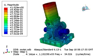
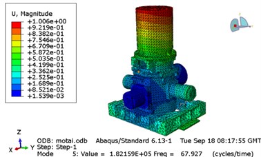
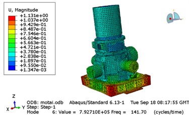
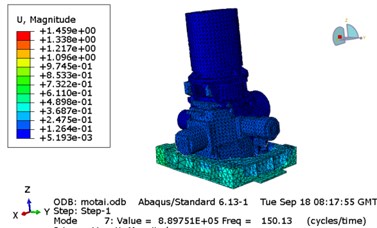
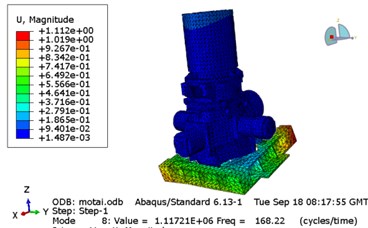
Generally, the experimental modal analysis of the main parts is needed, and then the results are compared with the finite element analysis to obtain a relatively accurate finite element model. Because the error of free modal analysis for a single part is not very large, it usually can be controlled below 5 %, but it is difficult to get relatively accurate results for modal analysis of composite structures. It is the boundary condition which makes it difficult for finite element analysis. Due to the limitation of experimental conditions and cost, the experimental modal analysis only get natural frequency and the finite element modal analysis is carried out. Through the transfer function, we can contrast the natural frequency between simulation and experiment in Table 1. Since the torsion stiffness of the isolator is not considered, the first three modes of the compressor are removed and the 4-9 modes are obtained in Fig. 8. It can be seen from the figure that the first two modes are body modes and the last four modes are base modes.
Table 1Natural frequency contrast (Hz)
4 | 5 | 6 | 7 | 8 | 9 | |
Simulation | 54.0 | 67.9 | 141.7 | 150.1 | 168.2 | 169.2 |
Experiment | 56.4 | 65.7 | 143.8 | 153.2 | 156.1 | 166.3 |
Fig. 8Modal analysis of compressor

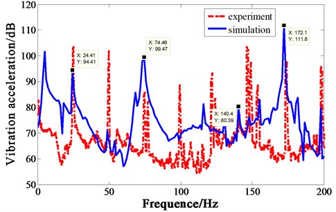
Vibration acceleration of four measuring points on the base is shown in Fig. 9. The spectrum trend of the four experiment points are basically the same, only the amplitudes of some frequencies are slightly different. For simulation, crank-connecting rod mechanism and machine body interact with each other. The force of the motion pair is acquired in the previous section, which is loaded on the finite element body by MPC coupling. The force of 1-4# motion pair in the opposite direction, with 5# motion pair force in the previous direction, after 50 cycles of iteration, the force in time domain is obtained. Loaded the force on the machine body, simulation is carried out. Since the test acceleration of four points is nearly the same, only point 1 is compared with the simulation in Fig. 10. Due to the existence of the isolator, the acceleration response should have a resonance peak in the frequency band below 10 Hz. The experiment sensor cannot accurately measure the low frequency value, so there is no obvious resonance peak in the experiment value. If the low-frequency resonance peak needs to be measured accurately, a special low-frequency acceleration sensor is needed [12, 13].
By comparing the experiment with the simulation, it is obvious that the acceleration simulated is generally higher than experiment, because the compressor mass is large and the foundation is flexible. In the simulation process, the foundation is treated as a rigid body. Although the foundation strength is high, the vibration acceleration level is 109.4 dB in 10-10 kHz band during the test. From the vibration acceleration curve, it can be seen that there are several resonance modes near the frequency doubling of 3, 5 and 6, which should be avoid by design. From the above analysis, it can be concluded that the resonance below 150 Hz is mainly caused by insufficient body strength, and the resonance between 150 Hz and 200 Hz is mainly caused by insufficient rigid strength of the base.
Fig. 9Vibration acceleration of four measuring points on the base
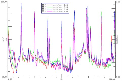
Fig. 10Vibration acceleration comparison
6. Conclusions
In this paper, the dynamic model of crank connecting rod mechanism of star compressor and the finite element model of the whole machine is established. Combining with the measured data of cylinder pressure, the vibration acceleration of the base is simulated, and the experiment results are compared with the finite element results. The conclusions can be drawn as follows.
1) Negative pressure exists in cylinder one, which makes the stress of piston one complex. The larger diameter of cylinder one makes the cylinder body less rigid and may increase the vibration.
2) Compressor has a large mass, so it is difficult to find a sufficient stiffness foundation. The vibration acceleration of the base by finite element method is higher than that of the experiment one due to the rigid treatment of the foundation. The simulation is consistent with the experiment in resonance and trend to some degree.
3) Traditional acceleration sensors cannot measure the low-frequency resonance of the isolator. Except the isolator natural frequency, the resonance below 150 Hz is mainly due to the insufficient rigidity of the body, the resonance between 150 Hz and 200 Hz is mainly due to the insufficient rigidity of the base. Cast the base and the body as a whole, which can theoretically increase the rigidity of the whole machine and reduce the vibration response.
References
-
Piston Compressor Design Compilation Group. Piston Compressor Design. Machinery Industry Press, Beijing, 1974.
-
Yu Yongzhang, Sun Siying, Chen Hongjun Technical Manual of Volumetric Compressor. China Construction Industry Press, Beijing, 2000.
-
Song Zhongshang Dynamic Design and Simulation Study on of Vibration of Rotary Compressor. Master Thesis, Shanghai Jiaotong University, Shanghai, 2015.
-
Liu Chengwu Dynamic analysis and noise prediction of the large-scale compressor. Doctor Thesis, Nanjing University of Technology, Heilongjiang, 2006.
-
Zhou Yu Dynamic Analysis of Reciprocating Compressor and Motion Simulation. Master Thesis, Northeast Petroleum University, Jiangsu, 2015.
-
Marriot L. Finite element calculation of rotor side-pull forces in single-phase induction motors. Proceedings of the International Compressor Engineering Conferences of Purdue, West Lafayette, 1994, p. 729-734.
-
Li Zenggang Detailed Introduction and Examples of ADAMS. National Defense Industry Press, Beijing, 2014.
-
Li Chaobo, Lou Jingjun, Zhang Zhenhai, et al. Optimal design of dynamic balance for reciprocating air compressor. Journal of Naval University of Engineering, Vol. 30, 2018, p. 44-48.
-
Xu Zengjin, Wang Shijie Dynamic characteristic of crankshaft in reciprocating compressor. Journal of Xi’an Jiaotong University, Vol. 44, 2010, p. 100-104.
-
Liu Weihua, Ang Haisong A new method for measuring cylinder pressure in reciprocating compressor. China Mechanical Engineering, Vol. 16, 2002, p. 24-27.
-
Levecque N., Mahfoud J., Violette D. Vibration reduction of a single cylinder reciprocating compressor based on multi-stage balancing. Mechanism and Machine Theory, Vol. 46, 2011, p. 1-9.
-
Guzzomi A. L., Hesterman D. C., Stone B. J. The effect of piston friction on the torsional natural frequency of a reciprocating engine. Mechanical Systems and Signal Processing, Vol. 21, 2007, p. 2833-2837.
-
Jiang Zhinong, Li Xin, Jia Yang, et al. Multi-body dynamic simulation research on the influence of piston engine crankshaft thrust bearings abrasion. High Technology Letters, Vol. 22, 2013, p. 426-435.
About this article

