Abstract
To overcome the limitation of terrain and ground objects, curved girder bridges normally adopt a single column pier, on which a single bearing or double bearings with small spacing are seated, making it weak in anti-overturning ability under eccentric load. Presently, the vehicle centrifugal force and seismic action are rarely considered when calculating the anti-overturning stability and tend to aggravate the deflection of curved girder bridges. In this paper, a calculation method is proposed to determine the anti-overturning stability coefficient under earthquake; the calculating equation of anti-overturning stability coefficient under static action is modified. The results show that the influence of centrifugal force cannot be neglected. Otherwise, the calculation of overturning stability is unsafe. The anti-overturning stability of curved girder bridges under earthquake is lower than that under static action. Further, the effect of different structural parameters on the anti-overturning stability coefficient under static and seismic action is similar: the anti-overturning stability coefficient decreases with the growth of bridge deck width, while first decreases sharply and then increases slowly with the growth of curvature radius.
Highlights
- An equivalent static loads method is adopted to calculate the anti-overturning stability coefficient of curved girder bridges under seismic action.
- The calculating equation of anti-overturning stability coefficient under static action is modified.
- The influence of structural design parameters on the stability of curved-girder bridges is disclosed .
1. Introduction
Over the recent decade, bridge overturning and instability under vehicle load have been reported occasionally. Investigations found that these incidents were partially caused by severe overloading of vehicles, especially when lines of heavy trucks drove in the near-side lane and caused skewed loading. In addition, due to the limitation of terrain and ground objects, curved girder bridges normally adopt single column pier, on which a single bearing or double bearings with small spacing are seated, making it weak in anti-overturning ability under eccentric load. Although bridge overturning is a rare event, the consequence is catastrophic should it occur. Enormous research has been successfully verified the anti-overturning performance of curved girder bridges during the previous decades. However, the anti-overturning stability analysis is mainly based on static conditions, with rare consideration for the seismic action. For curved girder bridges with consolidated piers and girders, the overturning moment increases due to the seismic action, and torsion and rollover of the main girders may occur, resulting in flexural-shear damage to the piers. For curved girder bridges with bearings seating on the pier top, the seismic action causes larger horizontal displacement between the pier and the beam of curved girder bridges. In addition, the seismic inertia force of main girder poses potential risks of bearing disengaging, girder falling or lateral buckling. Therefore, it is necessary to consider the seismic action when determining the girder overturning stability.
W. Streit and R. Mang [1] (1984) first put forward the concept of lateral anti-overturning stability coefficient of bridge; G. W. Wellman [2] (2008) simulated the whole process of bridge overturning and collapsing through numerical calculation and defined the boundary between instability and stability. Yuan Shezhen [3] et al. (2008) discussed the affecting factors of lateral stability of bridges based on the space beam gird theory and built a simplified calculation formula for lateral stability of bridges. Pennington and Steven M. [4](2010) analyzed the overturning process of Bussey railroad bridge. Based on the data collection of the bridge accident, they summarized the reasons for the bridge overturning and proposed relevant engineering suggestions. Heegaard W. and Ward T. [5] (2007) studied the overturning of curved girder bridges and proposed the model and method to analyze the overturning of curved bridges. Zhuang Dongli [6] (2014) took a ramp bridge as an example to analyze the anti-overturning stability of bridges exposed to different vehicle loads and discussed the relationship between overturning stability and bearing spacing. Cao Jing et al.[7] (2014) derived the anti-overturning stability calculation formulas of straight and curved girder bridges. Peng Weibing et al. [8-11](2015) took Chunhui Bridge as the engineering background, divided the overturning process into different stages, and then defined two critical conditions of the side bearing disengaging and overturning stability using the finite element model to analyze the overturning failure mechanism of single column pier girder bridge, and summarized different failure modes of single-column pier girder bridges. A practical, simplified calculation method for the anti-overturning failure bearing capacity of single-pier girder bridges is proposed by comparing with the standard method. Wan Shicheng [12] (2015) held that it was insufficient to judge bridge overturning merely by bearing disengaging; Wang Bingxian [13] (2017) took the disengaging of all bearing as the determining criterion of overturning; Xiong Wen et al. [14] (2018) put forward four critical overturning conditions successively occurred according to the mechanical properties of pot bearings using safety coefficient to quantitatively determine the overturning resistance of pier girder bridges under different critical conditions, combining with the actual rollover accidents to verify its rationality. Taking the three-span curved girder bridges as an example, the impact of curvature radius and central angle on the overturning axis and the anti-overturning stability coefficient was discussed.
Nielson B. G. and Desroches R. [15] (2007), Burdette and Howard S. C. et al. [16] (2004) studied the response characteristics and mechanisms of the bridge bearing under seismic action through seismic excitation, and analyzed the change law of the bearing reaction; George T. Michaltsos and Ioannis G. Raftoyiannis et al. [17] (2008) proposed a theoretical method to determine the overturning and displacement of bridges under seismic action; Yao Jiancong [18] (2017) analyzed the stability of curved-girder bridges with single column pier under the seismic action with the time-history method, holding that the combination of the vehicle eccentric load and horizontal seismic action imposed a major impact on the overturning stability of the bridges, while the combination of the vehicle partial load and the vertical seismic action imposed a minor impact on the overturning stability of the bridges. However, the authors mistakenly deemed that when calculating the anti-overturning stability coefficient, the seismic action merely affected the anti-overturning moment, and the overturning moment stayed unchanged. Zhang Chao [19] (2014) applied the base sliding isolated technique to continuous rigid frame bridges with high piers, summarized the discriminating conditions and calculating procedures of transverse anti-overturning of bridges, and proposed a flexible anchorage against lateral anti-overturning.
To sum up, enormous achievements have been made in the research on the anti-overturning performance of curved-girder bridges. Meanwhile, there still exist the following deficiencies:
a) Currently, most of the researches on the anti-overturning stability of bridges by domestic and foreign scholars focused on the influence of static force, and less on the anti-overturning stability of bridges under the seismic action. When considering the analysis of anti-overturning stability under the seismic action, the existing research mistakenly believed that the seismic action only affected the anti-overturning moment, while the overturning moment stayed unchanged. It is necessary to propose more reasonable calculation and analysis methods.
b) In the calculation of anti-overturning stability under static force, existing studies rarely considered the influence of vehicle centrifugal force. For curved girder bridges, the existence of vehicle centrifugal force will increase the overturning moment and reduce the anti-overturning stability coefficient. Therefore, it is necessary to study the influence degree of centrifugal force.
Aiming at the curved-girder bridges, the paper built the calculating formula of anti-overturning coefficient of bridges exposed to the seismic action using the equivalent static loads method, revised the calculating formula of stability coefficient of curved-girder bridges under static action, and disclosed the influence of structural design parameters on the stability of curved-girder bridges.
2. Anti-overturning stability analysis of curved girder bridges under static action
2.1. Calculation formula of anti-overturning stability of curved girder bridge under static force
Specifications for Highway Bridges [20, 21] stipulates the lateral stability and adopts monolithic section of the simply-supported beams and continuous beams to check the anti-overturning according to Eq. (1):
where is the anti-overturning stability coefficient, is the effect design value to make the superstructure stable, is the effect design value of capsizing and instability of superstructure, is the vertical spacing between ineffective bearings and overturning axis at the th pier, is the bearing reaction of the failed bearing at the th pier under permanent action, which is calculated by the effective bearing system of all bearings, is the bearing reaction of the failed bearing at the th pier under variable action, which is calculated by the effective bearing system of all bearings and valued by combination of standard values, and the value of vehicle load (including impact effect) should be valued according to the most adverse load distribution.
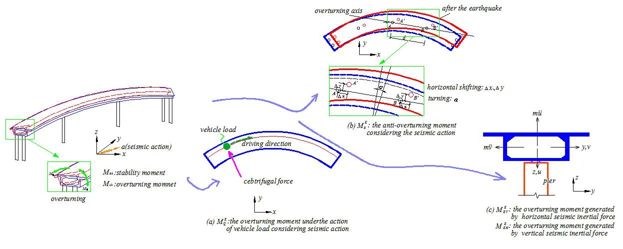
The overturning axis of curved girder bridge is shown in Fig. 1. The determination of the safety coefficient of the bridge anti-overturning is given in literature [21]:
where, is the acreage enclosed by the overturning axis and lateral loading lane, and is the maximum vertical distance between the loading lane and the overturning axis.
Fig. 1Schematic diagram of curved girder bridge overturning
For curved girder bridges, the paper holds that due to the centrifugal force component of vehicle load, the overturning moment increases, and the anti-overturning safety coefficient decreases accordingly. Therefore, the formula for calculating the anti-overturning safety coefficient of curved girder bridges under static load considering the influence of vehicle centrifugal force is given as below:
where is the centrifugal force coefficient, is the radius of curve, is the distance between the center of gravity of the vehicle and the overturning axis, taking the height 1.2 m above from the bridge deck to the overturning axle, and is the loading arc length.
2.2. Influence of centrifugal force on anti-overturning stability coefficient of curved girder bridges under static force
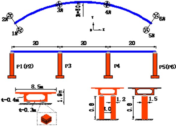
The overall layout of the curved girder bridge and the section size of the main components are shown in Fig. 2. The curve radius of the bridge is 50 m and the span 20 m; The superstructure is single-box and single-cell box girder made of C50 concrete. The main girder is 8.5 m wide and 1.9 m high; both sides of the bridge substructure are designed with double column piers, while the center of the substructure with single column piers of C40 concrete, and piers are 8 m high, both ends of pier 1.2 m in diameter, the middle pier 1.5 m in diameter, the whole bridge adopts the laminated rubber bearings, vertical stiffness of the bearing considered to be with infinite stiffness, and the lateral stiffness is 3000 kN/m.
The software package SAP2000 is used to build the finite element model of the curved girder bridge, where the girder adopts shell elements simulation, the pier adopts stretch beam element simulation, the bearing adopts linear link elements simulation, and the pier foundation adopts the method of consolidation regardless of the pile-soil interaction to the structure.
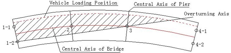
Fig. 2Overall layout and section of curved girder bridge (in m)
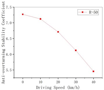
The overturning axis of the bridge is the connecting line of the middle two pier bearings. In combination with the limit requirements of vehicle driving speed in highway route design specification, it is assumed that the speed is 0 km/h (ignoring centrifugal force), 10 km/h, 20 km/h, 30 km/h and 40 km/h. Since the driving speed of the vehicle does not affect anti-overturning moment, the calculated results are all 15860 KN.m. As can be seen from Fig. 3 and Fig. 4, with the growth of vehicle driving speed, the overturning moment changes from 2,181 KN.m when centrifugal force is not considered to 2,907 KN.m when the speed is 40 km/h, and then the anti-overturning stability coefficient decreases from 7.3 to 5.4, with a variation range of 33 % and 26 %, respectively. The results show that it is not safe to calculate the anti-overturning stability coefficient when ignoring the influence of the centrifugal force in the current standard, and the relationship between the anti-overturning stability coefficient and the driving speed can be approximately linear.
Fig. 3Overturning moment of curved girder under different driving speeds
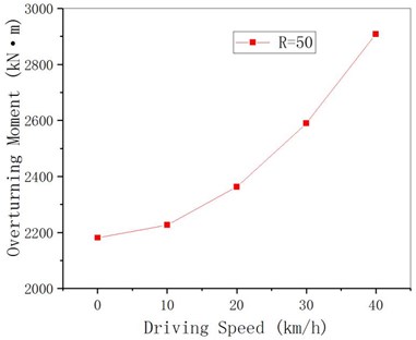
Fig. 4Anti-overturning stability coefficient of curved girder under different driving speeds
3. Anti-overturning stability calculation of curved girder bridges considering seismic action
Considering the overturning and instability under the seismic action is an important part in the design of building structures. It is clearly stipulated in relevant specifications [22] that the overturning moment and stability moment of structures under seismic action shall be checked in the seismic design of high-rise buildings. In the design specifications for bridge structures, only the anti-overturning calculation under static force is required, whereas the anti-overturning stability considering the seismic action has not been required. Since the seismic inertial force of curved beam will generate the torque to the outside of the curve, and the horizontal displacement of the outside of the curved beam will have an negative impact on the overturning moment and stability moment, thus reducing the anti-overturning stability coefficient of curved girder bridge, it is necessary to analyze the anti-overturning stability of curved girder bridge considering the seismic action.
Assuming the vibration coupling of the horizontal and vertical seismic actions is neglect, the anti-overturning stability of the curved girder bridge under seismic action is:
where is the anti-overturning stability coefficient considering the seismic action, is the effects combination considering the seismic action to stabilize the superstructure, and is the effects combination considering the seismic action to capsize the superstructure, is the anti-overturning moment considering the seismic action, is the overturning moment under the action of vehicle load considering seismic action, is the overturning moment generated by horizontal seismic inertial force, and is the overturning moment generated by vertical seismic inertial force on the overturning axis, is partial factors for vertical and horizontal seismic actions at the same time, which can be referred to the value of partial factors for building seismic design standards, is the combination coefficient considering vehicle effect under seismic action. Since the most unfavorable vehicle off-load accident synchronizing with seismic action is a minimal probability event, can be valued according to the observation data and engineering experience of the actual use of bridges, and the value of urban rail traffic bridges is larger than that of other bridges.
3.1. Overturning moment caused by seismic inertial force
Under horizontal seismic action, the inertia forces of the curved girder and vehicle increase the overturning moment of the curved girder bridge, and the overturning moment caused by the horizontal seismic inertia forces of curved girder and vehicle on the overturning axis can be expressed as:
where is the mass of girder and each mass point of vehicles (for vehicles, combination coefficient can be valued according to actual situation), is the horizontal acceleration response of the th mass point along the vertical direction of overturning axis to the ground, is the horizontal seismic acceleration of the ground along the vertical direction of overturning axis, is the height of center of mass of the th mass point from the overturning axis (i.e., the height from center of mass to bearing).
Due to the mass of the outer edge of curved girder is larger, the vertical acceleration produces the overturning moment to make the curved girder flip outward. Due to near-field earthquake is close to the zone of fracture, the vertical seismic acceleration attenuation is reduced [23-25], overturning moment caused by the vertical seismic acceleration effect should not be neglected; for near-field earthquake, the influence of the inertia force of vertical vibration on the anti-overturning stability should be considered.
The overturning moment caused by the vertical seismic inertial force of curved beam and vehicle on the overturning axis can be expressed as:
where is the mass of each mass point of girder and the vehicle (for vehicles, combination coefficient can be valued according to actual situation), is the vertical acceleration response of the th mass point relative to the ground, is the vertical seismic acceleration of the ground, and is the horizontal distance between center of mass of the th mass point and the overturning axis.
3.2. Influence of relative displacement of pier beam on overturning moment and stabilizing moment
Under the horizontal seismic action, translation and turn relative to the pier occur in the curved girder. Translation includes vertical movement along direction and horizontal movement along direction. With the position change during the curved girder movement, the bearing reaction force under dead load and variant load of bridge changes accordingly, while the overturning axis stays unchanged. The stability moment caused by the dead load, and the overturning moment caused by the variant load change. The larger the displacement is away from the overturning axis, the more unfavorable it is to the anti-overturning of the structure. Therefore, the stability moment considering the horizontal seismic action can be written as:
The overturning moment caused by the vehicle gravity considering influence of horizontal seismic action is:
where is the bearing reaction force of the failure bearing at the th pier after the position of the curved girder changes considering the horizontal seismic action under the dead load, to be calculated according to the effective bearing system of all bearings, is the acreage enclosed by the overturning axis and lateral loading lane after position change of curved girder under horizontal seismic action, is the loading arc length after position change of curved girder under horizontal seismic action, and is the maximum vertical distance between loading lane and overturning axis after position change of curved girder under horizontal seismic action.
Therefore, the anti-overturning stability formula of curved girder bridge under horizontal seismic action is obtained as:
Actually, the seismic action is a dynamic process varying with time, and Eq. (9) is also time-history. When calculating the minimum value on the time history should be valued.
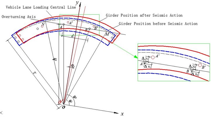
The plane coordinate system in Fig. 5 is established by taking the center point of the curved beam as the origin of coordinates and the direction parallel to the overturning axis as axial direction. and are two points corresponding to bearing centers on overturning axis of curved beam before horizontal movement. It is assumed that under seismic action, the curved girder will have a planar motion as shown in Fig. 5, where and are two points after and move through the planar motion, and are displacements of point along and directions of the movement, and are displacements of point along and directions of the movement. The distance between and is d, the distance between original point and the two points are both , let the distance between the original point and the center line of loading lane be , the overturning axis and the center line of loading lane intersect at point and , the angle between and axis is , and the angle between and axis is .
Fig. 5Position change of curved beam during horizontal seismic action
Based on the above assumptions, the motion of Fig. 5 can be decomposed into: the curved girder moves along and directions first with certain displacements of and by translational motion, and then rotates along the center of the curved girder by a certain angle . Assume on the curved girder, points and move respectively to position and by translational motion, curved girder center point to point , curved girder rotates around point again, point and , respectively, finally move to point and . Take the relative displacement of the pier and girder as the premise, the curved girder overturning axis has not changed in the process of horizontal movement, the intersection point of lane loading center line and overturning axis are marked as and as shown in Fig. 6.
From the geometric relationship in Fig. 6, it can be seen that: , and from Fig. 6, it can be seen that under the rotation angle , moves a displacement in direction to , a displacement of is made from to in direction:
Obtain to get .
Fig. 6Schematic diagram of position change of curved beam lane loading line during horizontal seismic action
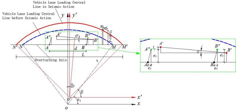
Fig. 7Schematic diagram of rotational displacement change of curved bridge during horizontal seismic action
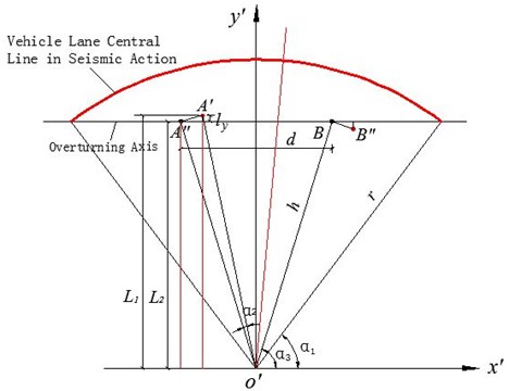
For a curved girder, whether it is first shifted and then rotated, or first rotated and then shifted, the value derived from the rotation of the curved beam stays the same. And it can be seen from Fig. 7, , , , , then:
Substitute Eq. (11) into Eq. (10) we obtain:
In Fig. 6, the point on the lane loading center line in the earthquake process in coordinate system satisfies , the coordinate value of point is the same as that on axis of point , the coordinate of point obtained is , and the coordinate of in the coordinate system is (, ), then:
In the coordinate system, the overturning moment caused by the uniformly distributed load on the driveway is calculated as below:
The arc length of the loading line , therefore, is the weight of the vehicle load, and the overturning moment provided by the vehicle gravity considering horizontal seismic action is:
where , is the maximum value of the vertical distance between the loading lane and the overturning axis before the earthquake, and can be obtained from Eq. (12) and Eq. (13), respectively.
4. Influence of structure parameters on overturning stability coefficient
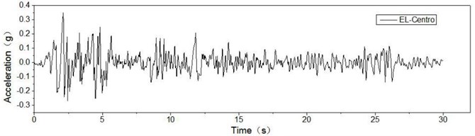
EL-Centro seismic wave was selected and its seismic time-history curve was shown in Fig. 8. The seismic intensity was set to 8 degrees. In light of specifications for the highway bridge seismic design, we modulated the horizontal acceleration amplitude to 0.3 g, vertical acceleration 0.17 g. Given 90° is the most unfavorable earthquake input direction for the anti-overturning stability of the curved girder, the earthquake excitation is vehicle carried out in accordance with the direction of 90°, according to the above formula for calculation of anti-overturning stability coefficient is derived. Considering the influence of vehicle centrifugal force under static force, it is assumed that the speed is 20 km/h when the radius of curvature is 20 m and 30 m, 40 km/h when the radius of curvature is 50 m and 80 m, and 60 km/h when the radius of curvature is over 120 m.
Fig. 8Time-history curve of site seismic action
Under seismic action, the following load combinations are considered:
• Combination 1: horizontal earthquake + vertical earthquake.
• Combination 2: horizontal earthquake +80 % vehicle eccentric load.
• Combination 3: vertical earthquake +80 % vehicle off-load.
• Combination 4: horizontal earthquake + vertical earthquake +80 % off-load of vehicles.
• Combination 5: horizontal earthquake + vertical earthquake +50 % vehicle eccentric load.
4.1. Radius of curvature
Assuming that other structural parameters remain unchanged and the radius of curvature is changed, the anti-overturning stability of curved girder bridge under static and seismic action is analyzed. It can be seen from Figs. 9-11 that: (1) the stability moment under seismic action is slightly lower than that without considering the seismic action, which is consistent with the change law of curved girder radius with and without considering the seismic action. With the increase of curvature radius, it first decreases sharply, then slowly decreases and then slowly increases. (2) considering and not considering the impact of the earthquake overturning moment with the increase of the radius of curvature first sharply reduced, then slowly reduced, and then slowly increased; For girder bridges with a small curvature radius, the overturning moment considering the seismic action is obviously larger than that without considering the earthquake. (3) considering and not considering the seismic action, the anti-overturning stability coefficient is consistent with the change law of the curvature radius.
Fig. 9MRE changes with radius of curvature
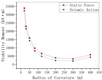
Fig. 10MEE changes with radius of curvature
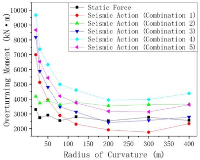
Fig. 11γqfE changes with radius of curvature
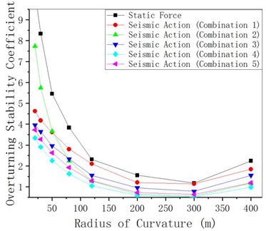
With the increase of the curvature radius, the anti-overturning stability coefficient first decreases sharply, then slowly decreases and then slowly increases. The inflection point is at the location with the curvature radius of 200 m-300 m. The anti-overturning stability coefficient of combinations under different load combinations varies, and the anti-overturning stability coefficient that considers the earthquake effect is smaller than the anti-overturning stability coefficient that does not consider the earthquake effect. The smaller the radius of curvature is, the greater the difference will be. Take combination 1 as an example, the difference is 100 % for 20 m and 30 % for 200 m.
4.2. Bridge deck width
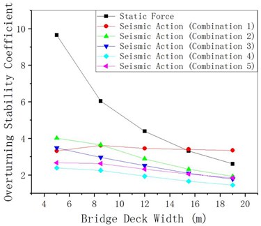
Assuming that structural parameters except the width of bridge deck remain unchanged the anti-overturning stability of curved girder bridges under static and seismic actions is analyzed. From Fig. 12 to Fig. 14, it can be seen that both the overturning moment and the stability moment increase with the growth of the bridge deck width, and the overturning moment under seismic action is smaller than the overturning moment under the action of static force. The anti-overturning stability coefficient under seismic action decreases slightly with the growth of the bridge deck width (the change is minor), while the anti-overturning stability coefficient under static action decreases significantly with the growth of the bridge deck width.
Fig. 12MRE changing with bridge deck width
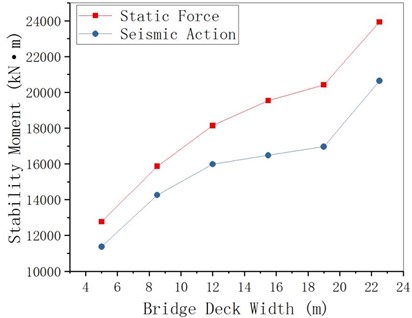
Fig. 13MEE changing with bridge deck width
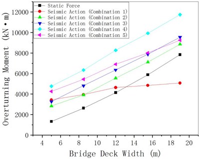
Fig. 14γqfE changing with bridge deck width
4.3. Bearing eccentricity
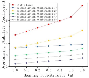
The pre-eccentricity of the bearing to the outside of the curve can be set on the middle pier of the curved girder bridge to reduce the torsion of the main girder, improve the in-homogeneity of the force on the inner and outer bearing, and prevent the inner bearing from disengaging. Provided that other parameters remain unchanged, change the bearing eccentricity of the pier bearing in the bearing to analyze the overturning stability of the curved girder bridge under static action and seismic action. From Fig. 15 to Fig. 17, it can be seen that the stability moment under seismic action increases with the bearing eccentricity, the overturning moment changes little with the bearing eccentricity, and the anti-overturning stability coefficient slightly increases with the bearing eccentricity value (changes little).
Fig. 15MRE changes with bearing eccentricity
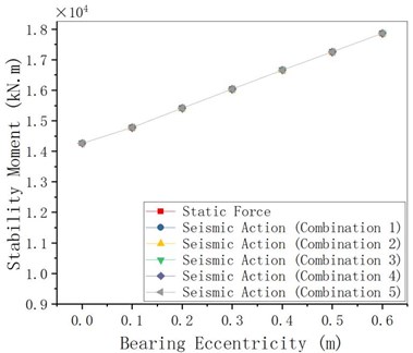
Fig. 16MEE changes with bearing eccentricity
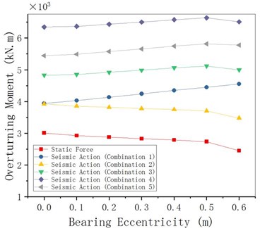
Fig. 17Coefficient changing with bearing eccentricity
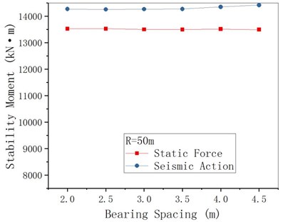
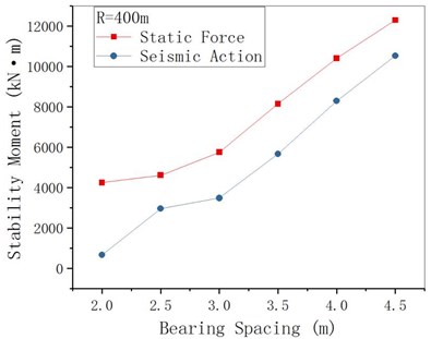
4.4. Bearing spacing
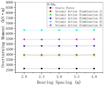
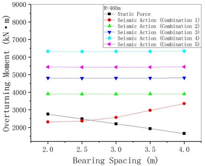
Take 50 m and 400 m respectively, and change the bearing spacing assuming other structural parameters remain unchanged. The anti-overturning stability analytical results are shown in Figs. 18-20. Because when 50 m, the overturning axis of the bridge is the connecting line of two middle pier bearings, the change of abutment distance of joint end (abutments) has little effect on the overturning moment, stability moment and anti-overturning stability coefficient. For 400 m when the bridge axis for the league side lateral (outboard bearings at the abutments) bridge pier bearing attachment, under seismic action overturning moment as united end bearing spacing increases, the stability against overturning coefficient end bearing spacing increases, its amplitude is smaller than the static under the action of an increase margin. It shows that for curved girder bridges with a small radius of curvature, the change of the junction bearing spacing has little effect on the stability against overturning, while the increase of the junction bearing spacing in the case of large curvature is helpful to the stability against overturning.
Fig. 18MRE changing with bearing spacing
a)
b)
Fig. 19MEE changing with bearing spacing
a)
b)
Fig. 20γqfE changing with bearing spacing
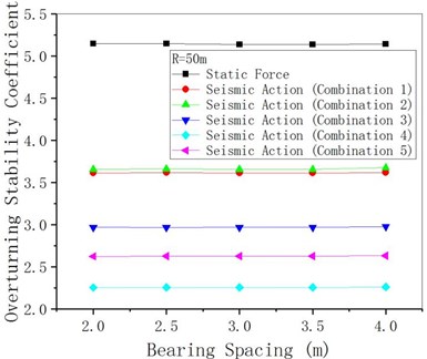
a)
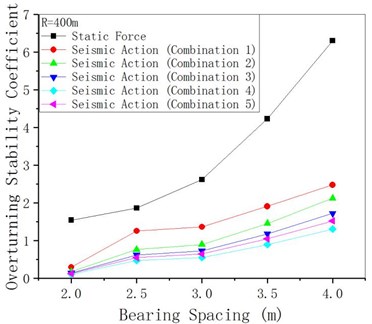
b)
5. Conclusions
1) Considering the influence of vehicle centrifugal force, the formula for calculating the anti-overturning stability of curved girder bridges under the action of static force is modified. The checking calculation of anti-overturning stability under static action does not consider the influence of centrifugal force, and lead to unsafe calculation results. The anti-overturning stability coefficient decreases approximately linearly with the increase of vehicle driving speed, with a maximum difference of 33 % for 50 m.
2) The equivalent static loads method is adopted to calculate the anti-overturning stability coefficient of curved girder bridges under seismic action, considering horizontal moment of inertia, vertical moment of inertia and moment acting on eccentric load of the vehicle, and the anti-overturning stability of curved girder bridge under various working conditions is simulated and calculated. The results show that the anti-overturning stability coefficient of curved girder bridges under seismic action is lower than that under static force, and the seismic action on the anti-overturning stability must be considered in the case of strong earthquake, otherwise the anti-overturning stability coefficient of curved girder bridges will produce a deviation of up to 58 %, leading to serious earthquake damage.
3) The anti-overturning stability coefficient of curved girder bridge under static force and seismic action is basically consistent with the change law of structural parameters of curved girder, that is, the anti-overturning stability coefficient decreases with the growth of bridge deck width; and increases with the growth of bearing eccentricity; As the radius of curvature increases, it first decreases sharply and then slowly, and then increases slowly when 200 m-300 m; For curved girder bridges with a large curvature ( 400 m), it increases with the growth of the distance between the abutment and the end, but it has little influence on the change of the distance between the abutment and the end of curved girder bridges with a small curvature ( 50 m); In general, the anti-overturning stability coefficient of curved girder bridges under seismic action changes less with structural parameters than that under static
References
-
Streit W., Mang R. Uberschlagiger Kippsicherheitsnachweis Fur Stahlbeton-and Spannbetonbind-er. Bauingenieur, Berlin, 1984.
-
Wellman G. W. Peer Review of the National Transportation Safety Board Structural Analysis of the I-35W Bridge Collapse. Technical Information Center Oak Ridge Tennessee, 2008.
-
Yuan Shezhen, Dai Gonglian, Wu Jianwu Discuss the landscape orientation overturn stability of single post wide continued girder bridge. Chinese and Overseas Architecture, Vol. 7, 2008, p. 154-157.
-
Pennington Steven M. The Bussey railroad bridge collapse. 5th Forensic Engineering Congress, Washington, United states, 2010.
-
Heegaard W., Ward T., Clinton J., et al. I-35W bridge collapse and response. Academic Emergency Medicine, Vol. 20, Issue 9, 2013, p. 933-933.
-
Zhuang Dong-Li Study of overturning stability issues of box girder bridges under action of eccentric load. Bridge Construction, Vol. 44, Issue 2, 2014, p. 27-31.
-
Cao Jing, Liu Zhi-Cai, Feng Xi-Xun Analysis of overturning stability of straight and curved bridges with box sections. Bridge Construction, Vol. 44, Issue 3, 2014, p. 69-74.
-
Peng Wei-Bing, Xu Wen-Tao, Chen Guang-Jun, Lu Fei-Yong calculation method for anti-overturning capacity of single column Pier Girder Bridge. China Journal of Highway and Transport, Vol. 28, Issue 3, 2015, p. 66-72.
-
Peng Weibing, Cheng Bo, Shi Xianhao, Xie Bo Research on mechanism of overturning failure of single column pier beam bridge. Journal of Natural Disasters. Vol. 23, Issue 5, 2014, p. 98-106.
-
Peng Wei-Bing, Pan Ruo-Dan, Ma Jun, Jiao Bin Study of overturning failure modes and anti-overturning calculation methods for single-column pier beam bridges. Bridge Construction, Vol. 46, Issue 2, 2016, p. 25-30.
-
Weibing Peng, Fei Dai, Ertugrul Taciroglu Research on mechanism of overturning failure for single-column pier bridge. International Conference on Computing in Civil and Building Engineering, 2014, p. 1747-1754.
-
Wan Shi-Cheng, Huang Qiao Overturning stability of continuous beam bridge with single column pier under eccentric load. Journal of China and Foreign Highway, Vol. 35, Issue 4, 2015, p. 156-161.
-
Wang Bing-Jian, Zhao Hang, Peng Wei-Bing, Pan Li-Jie Lateral stability calculation theory and verification of single-column Girder Bridge. China Journal of Highway and Transport, Vol. 30, Issue 9, 2017, p. 93-100.
-
Xiong Wen, Lu Sheng-Di, Gong Xuan, Cui Shan-Shan, Ye Jian-Shu Critical condition analysis of overturned bridges with single-column piers and applicability of design standards. China Journal of Highway and Transport, Vol. 31, Issue 3, 2018, p. 49-58.
-
Nielson B. G., Desroches R. Seismic performance assessment of simply bearinged and continuous multispan concrete girder highway bridges. Journal of Bridge Engineering, Vol. 12, Issue 5, 2007, https://doi.org/10.1061/(ASCE)1084-0702(2007)12:5(611).
-
Burdettee G., Howard S. C., Ingram E. E., et al. Behavior of prestressed concrete piles bearinging integral abutments. ASCE Conference Proceeding, Vol. 137, Issue 23, 2004, p. 1-6.
-
Michaltsos George T., Raftoyiannis Ioannis G. A mathematical model for the rocking, overturning and shifting problems in bridges. Engineering Structures, Vol. 30, 2008, p. 3587-3594.
-
Yao Jian-Cong Lateral Instability and Seismic Analysis of Single Column Pier Continuous Box Girder Bridge. Chongqing Jiaotong University, 2017.
-
Zhang Chao Application of Sliding Base Isolation Technology in the Rigid Frame Bridge. Changan University, 2017.
-
JTG D62-2012. Design Code for Highway Reinforced Concrete and Prestressed Concrete Bridges and Culverts (Draft for Comments). China Communications Press, Beijing, 2012.
-
JTG 3362-2018. Code for Design of Highway Reinforced Concrete and Prestressed Concrete Bridges and Culverts. China Communications Press, Beijing, 2018.
-
JGJ 3-2010. Technical Specification for Concrete Structures of High-rise Buildings. China Architecture and Building Press, 2010.
-
Ye Kun, Zhang Zi-Xiang, Zhu Hong-Ping Influence of near-field vertical Groung motions on the seismic response of LRB base-isolated structures. Engineering Mechanics, Vol. 33, Issue 4, 2016, p. 49-57.
-
Collier C. J. A procedure for combining vertical and horizontal seismic effect effects. Journal of Earthquake Engineering, Vol. 5, Issue 4, 2001, p. 521-539.
-
Wang Wei-Yi Effect of the Near-Filed Vertical Ground Motion on the Seismic Response of R/C Frame. Hunan University, Changsha, 2010.
Cited by
About this article

This work was financially supported by National Natural Science Foundation of China through Grant 51778471, Scientific Project of Education Department of Jiangxi Province GJJ160620, Science and Technology Project of Communications Department of Jiangxi Province 2016C0006.
