Abstract
A real case study is represented of abrupt failures in a new multi-motor gear drive of vertical rolls in the heavy slabbing mill. Modal analysis is conducted, and the lowest torsional vibration modes are verified by the data from an industrial plant. Conditions of parametric resonances due to variable stiffness of teeth are determined within the range of working speed. The branched gear drive is investigated by the non-linear dynamical model with backlashes. It is shown that instantaneous dynamic loads in driveline are strongly dependent on the difference in gap sizes and phase shift between two intermediate gears in the output gear wheel coupling. Deviation in electrical parameters by 0.5 % is considered as the additional cause of not equal load sharing of parallel motors. Results of this research allowed preventing further failures of the gearbox and optimizing slabbing mill control. The proposed approach can be used in other multi-motor machines.
Highlights
- Dynamical model is developed of the multi-motor heavy slabbing mill including electric motors
- Modal analysis of the split-path driveline is represented and parametric resonances are identified
- Influence of backlashes and non-synchronous meshing is investigated on the load sharing between gears
- Deviation of electric motors parameters is considered as an important factor of asymmetrical loading
- Conducted research allows improving the multi-motor gear drives, their control and condition monitoring
1. Introduction
Multi-motor, split path power or so-called summation drives are used in large-scale machines and rotating aggregates when the technological capabilities of equipment manufacturers limit the dimensions of gearboxes of traditional design. The use of a multi-motor drive allows, depending on the specific circuit, to reduce the power of individual electric drives and the total cost of the unit several times. Deep separation of power flows is considered rational, i.e. their summation at the last stage, where the loads are maximal. An additional advantage of multi-motor drives is reducing the inertia of every drive, which is important for precise control of industrial machines.
In addition to the positive features of multi-motor gear drives, there are certain design and operational problems. This concerns, first of all, the need to eliminate static uncertainty, ensure equal angular gaps, optimal selection of the number of flows and joint control schemes for electric drives, which not only equalize static loads, but also suppress out-of-phase oscillations of branches due to the inaccurate gears (run-out, eccentricity, transmission errors).
The presence of opened gaps in the kinematic pairs of any rotating machines significantly affects the overall response to external loads, e.g. in mining excavators with multi-motor drives. The increased dynamics in the gear drives of heavy hot rolling mills is occurring due to specific technological loads when pair of driven rolls capture metal in harsh operating conditions with increased wear and backlashes in split path drivelines. Especially significant is the effect of backlashes opening when asymmetry exists in parameters of parallel working electric drives of the machine, which is operated under reversing regimes with stepwise or impulsive loads. In rolling mills, the high torsional loads do not allow the use of planetary gears for rolls driving. To increase the power of some steel processing aggregates, e.g. strip coilers in cold rolling mills, 2-3 motors are axially connected with short intermediate shafts and no problems have been reported on their synchronous working.
In addition to abovementioned reasons, there are internal factors of dynamics that are often not accounted for when gearboxes are designed as a partial subsystem of a whole driveline. One of these factors is a periodic change of teeth stiffness, which plays its role even under constant speed and load. This disturbance may cause parametric resonances, which are not possible to suppress by linear damping and leading to severe torsional vibrations comparable by amplitude to the static technological torques within certain ranges of speed.
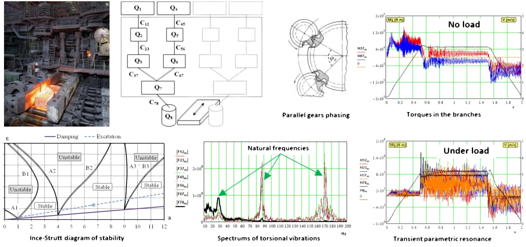
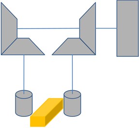
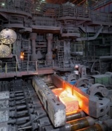
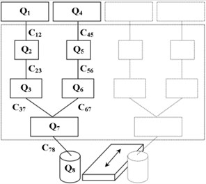
The research described in this paper is initiated by the accident with critical failures of gears in a modernized gear drive of the heavy slabbing mill. The single motor drive system worked for many years (Fig. 1(a)) was replaced with the new multi-motor drive system (MMDS) in order to add power and to increase overall plant productivity. Vertical rolls are driven by two-stage spur gear MMDS, which consists of branched first stages with direct current (DC) four motors (Fig. 1(b)). These electric motors have independent excitation scheme with pairwise parallel speed control for each vertical roll. Horizontal rolls of the second stand of the slabbing mill are directly driven by two DC motors via spindles without a gearbox.
Right after the new gearbox commissioning, an increased level of vibrations was observed, which finally resulted in dramatic failure and long-time downtime of the slabbing mill. After gearbox repair and replacement of main gears, vibration continued to be at a high level and customer decided to investigate such unexpected behaviour. Internal dynamical processes were suspected as a reason for early failures because static load limits for this gearbox were definitely not exceeded during several months of mill operation.
Possible problems in the drive of vertical rolls may appear from interaction with horizontal stand with much high power when they are not synchronized by the linear speed of rolls. In this case, backlashes are opening in the gear pairs and high transient dynamic torques may affect tooth durability. Desynchronization of the neighbouring stands or incorrect velocity adjustment between individual drives of rolls in one stand causes periodic metal slipping, fluctuation of the tension between the stands, defects on the surface of the strip and the risk of dangerous damages of the whole mill [1]. In this relation, a method is proposed for control of universal stands in hot rolling mills [2]. Shock loads are reduced by automatic matching the speeds when the strip exits the preceding vertical stand and enters the horizontal stand.
Dynamic torque variation and stands interaction in the slabbing mill was investigated in [3], [4]. Results of experimental research showed the importance of this factor for mill reliability. Simplified synchronization systems were implemented to solve this problem [5]. In recent years, slabbing mill with the new MMDS was updated by the digital control system to limit loads and to synchronize speeds of two stands [6]. Measurements of torques in spindles using telemetry system indicated that ratio between the maximum dynamic and steady-state values does not exceed 2.0-2.1 that is considered as a good performance for the large reversal mills. Nevertheless, developers of this control system noted, that additional play of gaps in the gearbox adversely affect the durability of mechanical components. To eliminate this drawback, they recommended to install individual thyristor converters and to control each electric motor excitation by the difference signal of the motor’s armature currents. Preliminary dynamic analysis of this slabbing mill [7, 8] showed a possibility of high internal torsional dynamics. Internal forces due to a mutual inclination of shafts are estimated on the contact faces of gears.
Researches related to parametric oscillations are known in MMDS of the platform turning mechanism of bucket wheel excavators [9], tilting mechanism of converters [10-12], drives of tunnel boring machines [13, 14] and long-wall shearer [15]. To prevent abrupt failures, the advanced methods are designed for vibration diagnostics of multi-motor planetary gearboxes of the bucket wheel drive of an excavator [16, 17].
Different sources of parametrical excitation are investigated in rolling mills [18-23]. Although the nature of parametric vibration is a well-known and investigated phenomenon [24-26], this problem is remaining a challenge. Some methods are proposed of gears profile modification [27] and gears phasing [9, 28] with taking into account contact friction and transmission errors [29]. Those methods are applicable only at the design stage. During the operation period, some elastic damping elements can be implemented in the spindles to reduce overall input impacts [30, 31], which is not concerned with internal gearbox dynamics. Diagnostic methods [32, 33] and torsional dynamics monitoring based on special signal processing of motor current [34, 35] and strain gauges telemetry tools [36, 37] are not feasible due to low dynamics at spindles.
Equivalent load sharing in MMDS can be improved by electric drive control [38-42] and active damping of torsional vibrations [43-49]. However, these methods are applicable for only two masses gearless drive systems (motor and rolls) and are not quite suitable for parallel electrical drives control in slabbing mill.
With the limited possibilities of loads measurement inside the gearbox, mathematical models are widely used for dynamic simulation of gear drives with backlashes non-linearity [50-54] including detailed modal analysis of geared drivelines [55, 56].
Summarizing the wide scope of studies, we can classify them as follows:
– optimal control for equal load share between parallel drives;
– vibration diagnostics of geared drivelines;
– analysis of gears phasing in planetary gear drives;
– estimation of kinematic errors influences on gears meshing;
– monitoring of mechanical loads by the electric drives current;
– passive and active damping of torsional vibrations in drivelines;
– modelling of loads sharing in parallel branches;
– modelling of torsional vibration with non-smooth nonlinearities.
Following these approaches, in-depth analysis and mathematical simulation of dynamical processes in the multi-motor gear drive of the heavy slabbing mill is represented in this paper. Special emphasis is placed on the investigation of parametric excitation in spur gears and influence of gears phasing on out-of-phase torsional oscillations in the MMDS. Interactions between vertical and horizontal stands and deviation of electric motors parameters are emulated in the developed non-linear dynamical model.
2. Dynamical model
According to traditional approaches and methods of dynamic processes simulation in rolling mills, the driveline system of the stand is usually represented by the calculation scheme with a small number of lamped masses (from 2 to 4) and constant stiffness of elastic connections between them, taking into account backlashes as bilinear nonlinearities. This approach is quite correct, since peak values of load torques are usually appearing during the first period of oscillations (10-20 Hz) in the range of lowest modes of torsional oscillations, and the highest modes are decaying during this period. However, with parametric perturbation, higher modes can be sustained and amplified when natural frequency matches with the periodic parameter changes or their harmonics. Therefore, the mathematical model of a slabbing mill includes the inertia of two motors, all gears and roll with the added mass of the ingot. The backlashes and variable stiffness of the gears are taken into account in numerical simulation. Two independent symmetrical parts of each roll gear drives are combined into the whole gearbox housing, therefore only one part of the gearbox is considered (Fig. 1(c)).
Fig. 1Gear drive of vertical rolls in slabbing mill: a) previous single motor drive; b) new multi-motor gear drive; c) calculation scheme of one half of gearbox
a)
b)
c)
The designations and numerical values of the model parameters are shown in Table 1. All parameters are reduced to the roll rotation speed. The analysis showed that the spindle section has the lowest stiffness, and the first stage of the gearbox has the greatest stiffness. The inertia of the roll is 3 times less than the gear wheel and 3.5 times less than the moment of inertia of the motor. In such systems, when an instantaneous load is applied to the terminal mass (roll) with small inertia, significant oscillations of torques may occur.
Table 1Parameters of calculation scheme
Parameter | Description | Value | Units |
, | The inertia of one electric motor | 7 000 | kg m2 |
, | The inertia of one input gear | 2 100 | kg m2 |
, | The inertia of one intermediate gear | 1 700 | kg m2 |
The inertia of one output wheel | 5 200 | kg m2 | |
The inertia of one roll | 1 830 | kg m2 | |
, | Stiffness of one motor shaft | 15.7 108 | N m/rad |
, | Stiffness of one gear at stage I | 32.7 108 | N m/rad |
, | Stiffness of one gear at stage II | 13.8 108 | N m/rad |
Stiffness of one spindle | 0.61 108 | N m/rad |
Based on the adopted calculation scheme, the system of differential equations and the corresponding matrix of parameters are given in Eqs. (1) and (2) respectively:
where – angle of inertial masses rotation (rad); – rotating inertia (kg m2); – equivalent damping coefficients (N m s/rad); – elastic torques (N m); , – driving torques of two motors (N m); – technological load applied to one roll, equal to half of rolling torque (N m), and:
2.1. Modal analysis
Modal analysis is conducted to understand drive dynamics. The natural frequencies of one roll driveline are represented in Table 2. Dynamical model is verified by the recordings of electric motors currents. The lowest natural modes are identified, the first is near the frequency ≈ 29 Hz and the second ≈ 41 Hz (see Fig. 2).
This is enough accurate coincidence taking into account some decrease for damped oscillations frequency. The highest natural modes are not able to identify by the electric drives signals because of limited to 100 Hz the sampling frequency in mill control. Some deviation of real frequencies can be as well due to a joined mass of rolled ingot coupled by contact friction with roll inertia in the deformation zone.
Three even natural modes , , (43, 152, 329 Hz) correspond to torsional vibrations of separated branches, while four odd modes , , , (30, 87, 172, 332 Hz) correspond to symmetrical oscillations of parallel branches in the gear drive (see Fig. 1 and Table 2). The first mode (30 Hz) has a node, i.e. point around which neighbouring inertias oscillate, in the spindle shaft. In this case, the masses oscillate out-of-phase with the roll’s mass and gaps opening in spindle may produce higher input loads on gears in case of non-equal load sharing between vertical drives or non-synchronous speed with horizontal stand. In the wide strip hot rolling mills, this node is located, as a rule, on the shaft between the motor and gearbox.
Fig. 2The spectrum of electric motors power
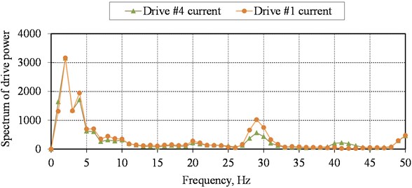
Table 2Natural modes of torsional oscillations
Parameters | Frequencies | ||||||
[rad/s] | 186 | 270 | 545 | 954 | 1078 | 2069 | 2085 |
[Hz] | 30 | 43 | 87 | 152 | 172 | 329 | 332 |
–0.079 | –0.543 | 0.363 | –0.156 | –0.118 | 0.024 | –0.024 | |
–0.067 | –0.367 | –0.118 | 0.475 | 0.495 | –0.443 | 0.433 | |
–0.060 | –0.265 | –0.326 | 0.500 | 0.420 | 0.551 | –0.556 | |
–0.079 | 0.543 | 0.363 | 0.156 | –0.118 | –0.024 | –0.024 | |
–0.067 | 0.367 | –0.118 | –0.475 | 0.495 | 0.443 | 0.433 | |
–0.060 | 0.265 | –0.326 | –0.500 | 0.420 | –0.551 | –0.556 | |
–0.040 | 0.001 | –0.700 | 0.001 | –0.360 | –0.001 | 0.078 | |
0.985 | 0.001 | 0.088 | 0.001 | 0.011 | 0.001 | –0.001 | |
The second mode (43 Hz) corresponds to out-of-phase oscillations of one branch against other parts of drive together with output gear wheel and roll . This mode may cause gaps opening in the stage II of the gearbox and additional cyclic loading on gear tooth.
The third mode (87 Hz) corresponds to out-of-phase oscillations of motors , , against gears in first branch , , second branch with output wheel , , and roll .
The highest modes (152, 172, 329, 332 Hz) show different combinations of phases with the opposite motion of separate pairs of gears as a whole body or output gear wheel against them. These modes are dangerous from the viewpoint of gears gaps opening and teeth shock loading, but their influence depends on damping factors in the torsional system.
The most generalized natural modes of this drive system are possible when two separate parts of the gearbox with two motors oscillate against each other (7.6 Hz) or in-phase (24.6 Hz) against the inertia of rolls with ingot. These modes coincide by phase with the first mode for separate parts of the gearbox (30 Hz) and therefore the calculation scheme in Fig. 1 is considered in research.
The opened angular gaps in the spindles have a significant impact on the dynamic loads in all sections of the driveline - from the spindle up to the motor shaft. However, when operator reverses mill and rolls capture the slab, drives usually are accelerated, gaps are kept closed by inertial torque of roll, and the dynamics in the driveline is not as high as could be when the mill is decelerated [47, 49]. Nevertheless, the proximity of several pairs of natural frequencies (ratio 1.43, 1.13, 1.01) indicates that this driveline is prone to beat of elastic torques resulting in torque amplification not only when metal is being captured by rolls, but also in the steady rolling mode.
2.2. Parametric excitation
Periodic changes in the stiffness lead to a change in the natural frequencies of the system and, by their nature, are parametric perturbations. Even small changes of these parameters under certain conditions, depending on the ratio of damping and disturbance, on the one hand, can cause increased oscillations in the mill, and on the other hand, these oscillations are important diagnostic signs, as they directly depend on the conditions of contact interaction in gearing in the focus of deformation.
For a two-mass system with one generalized variable, parametrically excited oscillations are described by the Mathieu equation:
where – the relative change in the natural frequency or the depth of modulation; – the frequency of parameter pulsation; – damping factor.
The standard form of the Mathieu equation can be obtained by substitution of variables:
After subsequent substitution terms Eq. (4) into Eq. (3), we obtain:
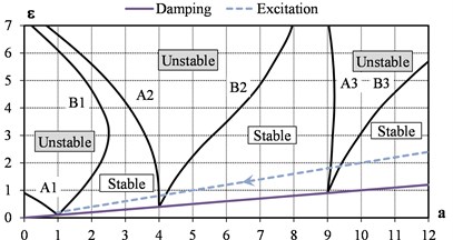
Solutions of Eq. (5) are special polynomials, which determine the stability regions of the system on the Ince-Strutt diagram (see Fig. 3) in coordinates . The diagram is symmetrical about the axis , since the sign of in Eq. (5) does not matter [57]. The more damping and less disturbance, the more stable the system. For a multi-body system, stability diagram is analysed for each natural frequency and perturbation frequency.
With an unlimited increase in the frequency of the disturbance , the imaging point with abscissa and ordinate moves along the dashed line to the origin of coordinates (see Fig. 3), where – tangent of inclination angle.
Fig. 3Ince-Strutt diagram of the parametrically excited system with damping: excitation – μ= 0.20; damping – 2δ= 0.10
The condition for an unlimited increase in the oscillation amplitude, i.e. the occurrence of parametric resonance, at an arbitrarily small value of the parameter pulsation (points on the axis of the diagram) is:
At a significant depth of the parameter’s pulsation, resonance may occur when the ratios of frequencies laying in a certain interval within unstable areas around the values from condition Eq. (6). The larger the pulsation value, the wider these areas are. Therefore, the frequency detuning from parametric resonance is more difficult than from usual resonance with external excitation, since the region of instability can be spread by a confidence interval for calculating the average natural frequency.
The linear damping in the system only narrows the instability regions slightly but is not capable of limiting the increase in the amplitudes of oscillations in the unstable areas of the diagram. Under the action of nonlinear viscous forces of resistance, the oscillation amplitudes are limited.
The approximate value of the coefficient , at which resonance of the order is possible, is determined by the relation [57]:
where – the decrement of natural vibrations. Oscillations can develop only above the solid line in Fig. 3 with the tangent of inclination angle 2.
To keep the gear ratio constant at each time point, it is necessary that the next pair of teeth contacted when (or earlier) the previous pair of teeth leave the contact. The duration of the contact, depending on the teeth number of the meshing gears, is characterized by the overlap contact ratio:
where – pressure angle; – centre distance; – gear module; , – outside and base radiuses of a pinion (1) and wheel (2) gears. Usually in large-scale gearboxes 1 2. Values of 1 are not desirable as there is no two-pair engagement. With increasing from 1 to 2, the duration of one-pair engagement is shortened, and with 2, three-pair contact overlap appears in gears. For spur gears with 1 2, the stiffness change is significant for dynamic simulations. With the number of teeth of the slabbing mill gear drive: 53/81 – stage I and 51/125 – stage II, the contact ratios are 1.78-1.79, therefore, a one-pair and two-pair engagement are possible.
At a maximal rolling speed of 3 m/s, the peripheral speeds in the gears: stage I – 13 m/s, stage II – 10 m/s. For the 7th class of gearbox manufacturing precision, taking into account the hardness of the teeth about 42-52 HRC, coefficient of gears meshing dynamics is 1.17–1.22 by the recommendations of ISO 6336, that corresponds to values of excitation 0.17-0.22. This coefficient accounts non-load and under load transmission errors.
According to experimental data from the similar heavy rolling mills [56] and other gear transmissions [58], the damping of the system is about 0.02…0.15 (assumed as an average for natural modes). Hence, in the gearbox of the slabbing mill, the stiffness pulsation 0.17-0.22 can exceed the critical value, at least for the first-order resonance ( 1), i.e. when the natural frequency is equal to half of the excitation frequency (2).
2.3. Intermediate gears phasing
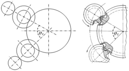
The analysis of the geometry of the gearbox made it possible to identify its features in relation to the use of a multi-motor scheme. The source of periodic disturbances is not the synchronization of the teeth of each pair of intermediate gears with gear wheels, due to the fact that the angle between the axes of their centres is 60.2° (see Fig. 4). In this sector, there is not an integer number of gear teeth 60.2°/2.88° = 20.903, where 2.88 is the angular pitch of the teeth of the output wheel of the gearbox. Therefore, in the process of rotation, periodic perturbations occur with teeth meshing frequency from one branch intermediate gear (), then from the another () with a phase shift: 0.903×2.88°×/180° = 0.0454 rad.
Given the phase shift, the formula for variable stiffness of the gears coupling is:
where – nominal gear stiffness (see Table 1); 0.17-0.22 – change in teeth stiffness without regard to wear; – gear meshing frequency; – number of teeth; – the variable angular speed of the corresponding shaft.
Fig. 4Schematic angular phasing of intermediate gears on the output gear wheel
2.4. Transitional parametric resonances
After mill reversing and during acceleration to the maximal rolling speed 3 m/s, the driveline passes five ranges - of parametric excitation shown in Fig. 5. For the first order resonances (2), gears meshing frequencies are given as half values: gear(I)/2 and gear(II)/2.
Fig. 5Resonance ranges of rolling speed
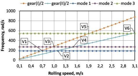
Mean values of resonant ranges of rolling speed are as following (m/s):
where , , – natural frequencies; – rolls radius; , – input pinion and output wheel gear teeth number; – total gearbox ratio (1,528×2,451 = 3,746). Values and are very close and a higher level of excitation is expected in the range 0.95,...,1.04 m/s of mill speed.
2.5. Model of backlashes
Backlashes in the nonlinear dynamical model are described by the following expression:
where – elastic torques (N m); – variable stiffness in shaft (N m/rad) (see indexes in Fig. 1); – angular shaft deformation (rad); – full backlash in coupling (rad); – coefficient of initial gap state (0 – fully opened, 1 – closed), which determines the opened part of full backlash, e.g. 0.80, means 20 % of full backlash is opened at the moment of load application. Research is conducted on the representation of non-smooth characteristics of backlashes with analytic functions [53], which showed that this approach has no effect on peak values of dynamical response, but has some restrictions on parameters and produce additional high harmonics in the frequency domain of torque signal.
When torque is at the zero levels, backlashes are opening in gear couplings with subsequent shocks until closing. Periodic changes of stiffness from average high value up to zero is dynamically equivalent to a depth of modulation value 1. This factor increases driveline susceptibility to parametric excitation.
2.6. Model of electric motors
The developed computer model of the vertical stand includes the equations of the direct current (DC) drives with independent excitation. The current of armature in the real mill is made separated for each roll of the vertical stand. For each of the two motors of the left and right rolls, the same reference value is supplied by voltage control to change the mill speed (the first control zone is used without changing the magnetic flux of the excitation).
Dynamical processes in DC motors are described by standard equations:
where – speed of rotational (rpm); – electric torque (N∙m); – elastic torque in the motor shaft (N∙m); - back electromotive force (EMF) (V); , – electrical and mechanical constants of motor; – magnetic flux of excitation; – load current in the armature (A); – equivalent motor armature inductance (H); – equivalent motor armature resistance (Ω); – armature voltage (V); – voltage drop on brushes (V); – motor rotating inertia (kg∙m2); – damping coefficient in shaft bearings.
Usually, terms and are neglected in electric drives simulations, but they are accounted in the model of MMDS as the additional factors of asymmetry in parallel branches of the gear drive. The mill control system is simulated in part to provide acceleration and deceleration of drives with programmable armature voltage supply.
Under the terms of the electric drives’ manufacturer, the difference of motor parameters is allowed within 5 %. After repair or change of any motor, the mill maintenance staff has to adjust the magnetic flux of each of the four motors in the idle mode. They change shunt resistances and currents in the excitation windings to reduce the effect of variation in the magnetic and electrical parameters. Their aim is to equalize the idle armature current of each of the four motors. The developed computer model allows investigating the influence of deviation in parameters (, – electrical and mechanical constants of the motor) on the dynamics of the mechanical system of the driveline.
Steel ingots are processed in slabbing mill within 10-13 reversal passes. After the first pass, two stands of the slabbing mill (horizontal and vertical rolls) begin to work in the continuous regime when they are connected via the rolled ingot with high axial stiffness. In this case, rolling torque in vertical stand will also greatly depends on rolls linear speed synchronization with the horizontal stand. To reduce this component of loading, the mill control system provides, individually for every pass, limiting of speed and its synchronization in neighbouring stands. Limiting of drives speed restrains stick-slip slab motion in the rolls, which is the most dangerous regime of the load causing severe damages in hot and cold rolling mills.
3. Model simulations
In each of 10-13 passes series of ingot processing, average rolling torque is changing due to different ingot sizes, metal temperature and reductions assigned by an operator in accordance with technological schedule table. Time of metal in stand and load ramp rising is changing from the first to the last passes due to slab section reduction and its front edge elongation. In simulations, the worst case of the load is admitted with instantaneous stepwise torque rising.
The peak values of torsional loads in slabbing mill driveline are characterized by the Torque Amplification Factors (TAF) for different sections (motor shafts, gears in two stages and spindle), which are calculated , where – peak elastic toque in couplings; – static technological torque, applied to roll. Maximal rolling speed of slabbing mill 3 m/s is assumed in simulations.
Technological torque on work roll is calculated depending on metal section and reduction in stands for every pass. Dynamical component of loads because of two stands interaction with a mismatch of their speeds is emulated by the additional torque applied to roll. Results of simulation are represented in Table 3. Indexes of the backlashes , gaps opening states and parameters of dynamics (TAF, M, F) in Tab. 3 and in Fig. 6 – Fig. 9 correspond to the notations given in Fig. 1.
Relation of TAFs from spindle backlash where 70 % of the total gap is accumulated is represented in Fig. 6. Every driveline section is very sensitive to backlashes in the spindle, hence, slipper pads replacement should be strictly scheduled in this mill maintenance.
Fig. 6Torque amplification factors (TAF) in different sections of driveline: TAF12 – motor shaft; TAF23 – stage I of the gearbox; TAF37 – stage II of the gearbox; TAF78 – spindle
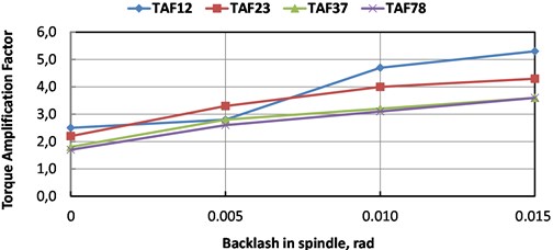
Under frequent technological reversals of the slabbing mill, the difference in dynamical loads is greater with more uneven wear of gears in the branches of the gearbox. In this regard, it is necessary during the repairs to choose a pair of gears with the smallest difference in the wear of the teeth or replace them both. Rolling speed has an insignificant effect on dynamics.
In the time domain, the results of the model simulation are shown in Fig. 7, there are the elastic torques in the gearbox during mill speed changing in idle mode and under stepwise load 900 kN m. Backlash in the spindle is assigned to its maximal value of 0.015 rad.
Table 3TAF for different backlashes Δ [rad] and gaps opening states KΔ= 0,…,1
No | Loading and backlashes | , motor shafts | , stage I | , stage II | spindle |
1 | Gearbox no gaps for both parts 0; 1; 0; 1; Spindle no gap 1; 0; 3 | 2,30 | 1,70 | 1,47 | 1,30 |
2 | Spindle gap opened 0; 0.015; 3 | 5,33 | 4,33 | 3,62 | 3,57 |
3 | 0; 0.010; 3 | 4,67 | 4,00 | 3,19 | 3,13 |
4 | 0; 0.005; 3 | 3,83 | 3,33 | 2,77 | 2,61 |
5 | 0; 0.005; 2 | 4,04 | 3,39 | 2,88 | 2,64 |
6 | 0; 0.005; 1 | 4,04 | 3,39 | 2,88 | 2,67 |
7 | Spindle gap half opened 0.5; 0.005; 3 | 3,40 | 2,83 | 2,43 | 2,24 |
8 | Spindle gap closed 1.0; 0.005; 3 | 2,50 | 2,20 | 1,85 | 1,70 |
9 | Gearbox gaps all half opened for both parts 0.001; 0.5; 0.001; 0.5; Spindle gap half opened 0.5; 0.005; 3 | 4,17 | 6,00 | 5,32 | 2,13 |
10 | Gearbox gaps all half opened for both parts 0.0001; 0.5; 0.0001; 0.5; Spindle gap half opened 0.5; 0.005; 3 | 3,67 | 3,67 | 2,98 | 2,22 |
11 | Gearbox gaps in stage I equal for both parts 0; 0.001; 1; 0.5; 0; 0.001; 1; 0.5; Spindle gap closed 1; 0; 3 | 3,00 | 4,00 | 2,98 | 1,65 |
12 | Gearbox gaps in stage II equal for both parts 0; 0.001; 1; 0.5; 0; 0.001; 1; 0.5; Spindle gap closed 1; 0; 3 | 3,10 | 3,67 | 4,26 | 1,65 |
13 | Gearbox gaps different for both parts 0.001; 0.5; 0.002; 0.5; Spindle gap closed 1; 0; 3 | 3,33 3,33 | 5,67 2,67 | 5,32 5,11 | 1,60 1,65 |
In idle mode, the passage through the resonant zones is accompanied by an increase in the amplitude of out-of-phase oscillations in the gears of the parallel branches of the gearbox. Torque crossing through the zero level causes gaps opening in the gears and back shocks of teeth. There are practically no fluctuations of torques in the spindle from gear meshing.
Under the load, torque amplification factors during the transient process are really not high (2.0,...,2.1) that corresponds to other studies of this mill. This is due to gaps closing during mill acceleration unlike TAF values in Table 3 where gaps were intentionally assigned opened (1).
The largest amplitudes of parametrically excited oscillations are observed in the couplings of the output wheel of stage II at a mill speed of about 0.9-1.0 m/s and 1.5 m/s. Other ranges , , do not show significant excitation.
Simulation of the meshing phase shift 0.0454 rad between two intermediate gears showed that this factor alone plays a minor role if no backlashes introduced in the model. However, non-synchronous meshing starts to play its role when gaps are opening in the same way as motors electrical parameters difference (see Fig. 8).
Simulation of small ( 0.5 %) electrical constant difference in one of the motors is represented in Fig. 8. This leads to static loads deviation and gaps opening with subsequent out-of-phase oscillations in both branches of the gearbox. Therefore, the use of MMDS requires quite accurate parameters tuning to equalize static loads. With a serial connection of two motors armature, the static load is better shared, but dynamical loads are not damped.
Fig. 7Transient dynamical torques in the different sections and regimes of driveline.
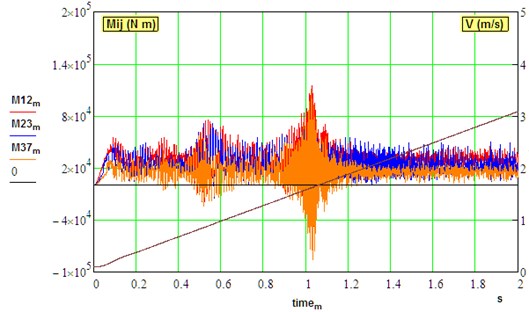
a) Idle mode (0,…, 3 m/s, 0.2, 0)
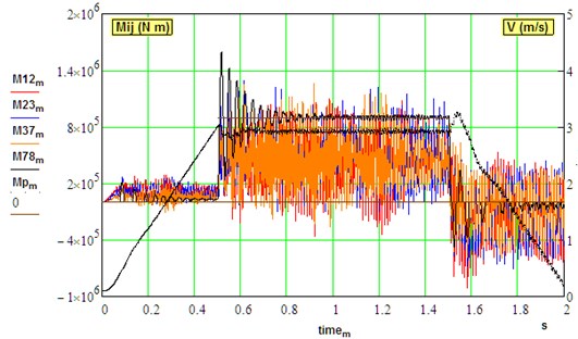
b) Under load (0,…, 3 m/s, 0.2, 0.015)
In the frequency domain, parallel branches exhibit a similar response. Spectrums of dynamical torques are shown in Fig. 9. In idle regime, electric motors demonstrate insignificant response at natural frequencies. Spindle shaft (F78) shows mainly low frequency (30 Hz) as predicted by modal analysis. All other sections: motor shafts (F12, F45), stage I (F23, F56) and stage II (F37, F67) of gearbox responded at higher modes of vibration (87, 172 Hz). Although the two highest modes of vibration (329, 332 Hz) are very close by frequency, they are not excited in the driveline. Natural modes at 43 and 152 Hz are as well not visible in the spectrums. Methods of backlashes diagnostics are proposed based on spectrum components in the range of natural frequencies of the multi-body systems [49, 53].
Fig. 8Dynamical torques in parallel branches of driveline under deviation of electrical constant of one motor: (v= 0,…, 3 m/s, μ= 0.1, ∆37 = ∆67 = 0.0001 rad, ΔKe=0.5 %)
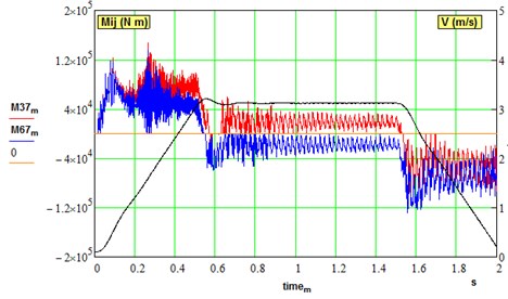
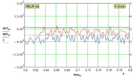
Fig. 9Spectrums of dynamical torques in the different sections of the driveline
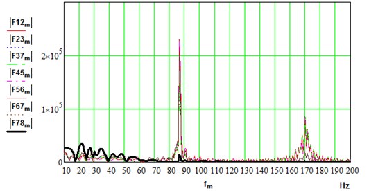
a) Idle mode (0,…, 3 m/s, 0.1, 0)
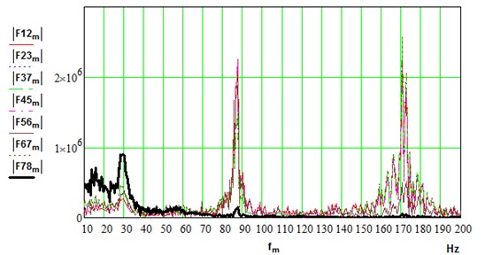
b) Under load (0,…, 3 m/s, 0.2, 0.015)
4. Conclusions
The obtained results on parametric oscillations in a slabbing mill are consistent with the data on an MMDS of platform turning in open-pit mines excavators and tilting mechanism in steel converter having spur gear couplings.
1) The possibility of parametric oscillations is discovered by MMDS simulation of the slabbing mill. Transient torsional resonances are identified when mill speed up and down and certain natural frequencies are in exact relation with gear meshing excitation in accordance with Ince-Strutt diagram. Damping is estimated and accounted in the model as the main factor of parametric vibration excitation.
2) The difference in gaps of the parallel gearbox branches leads to an increase in their influence on transient torsional dynamics compared with symmetrical distribution in case of even smaller values. The non-synchronous meshing of intermediate gears on the output wheel together with backlashes cause out-of-phase oscillations in each half of gear drive.
3) The influence of electrical parameters deviation in the two DC drives is estimated on the oscillations in the parallel branches of the gear drive. The results of this study are not only clarified the reasons for early gearbox failures but also allowed to improve the operation of the heavy slabbing mill. In addition, calculations of gearbox strength capacity and durability were improved by simulations of modernized gearbox design.
4) Monitoring and diagnostics of an MMDS should be specific in the analysis of vibration spectrum components. The characteristic frequencies can be masked by the natural frequencies and their harmonics appearing in case of gaps opening in parallel parts of gearboxes under not equal load sharing. From the other side, the presence of these components in the spectrum makes it possible to diagnose the wear of driveline elements. In addition, vibration amplitudes of transitional parametric resonances, their speed ranges may be informative parameters for technical condition estimation of heavy machines.
References
-
Kozhevnikova I. A., Kozhevnikov A. V., Sorokin G. A., Markushevskii N. A. Damping of vibrations in the primary drives of cold-rolling mills. Steel in Translation, Vol. 46, Issue 10, 2016, p. 739-741.
-
Khramshin V. R., Karandaev A. S., Evdokimov S. A., et al. Reduction of the dynamic loads in the universal stands of a rolling mill. Metallurgist, Vol. 59, 2015, p. 315-.
-
Zawada S. Dynamic torque variation in the drive of a large slabbing mill. Journal of Mechanical Working Technology, Vol. 7, Issue 1, 1982, p. 57-77.
-
Dobrucki W., Gregorczyk R., Zawada S. Modelling of the interaction of slabbing mills during the simultaneous rolling of slabs in both roll-pairs. Journal of Mechanical Working Technology, Vol. 19, Issue 3, 1989, p. 275-283.
-
Kharchenko G. N., Zemenkov A. A., Popov V. K. Relationships of the roll speeds of the universal stand of a slabbing mill. Metallurgist, Vol. 20, Issue 6, 1976, p. 410-412.
-
Svetlichny A. V., Zemlyansky A. I., Krivtsov A. I., et al. Limitation of the dynamic loads of a slabbing mill by means of an electric drive. Metallurgical Processes and Equipment, Vol. 1, 2013, p. 28-37, (in Russian).
-
Krot P. V. Parametric oscillations in rolling mills. Bulletin of the Dnipropetrovsk National Mining Academy, Vol. 3, Issue 13, 2002, p. 15-21, (in Russian).
-
Krot P. V. Dynamic processes in a multi-path gear drive of slabbing mill. Proceedings of National Technical University Kharkov Polytechnic Institute, Series: Problems of Mechanical Drive, Vol. 19, 2009, p. 96-105, (in Russian).
-
Chudnovsky Yu V. Dynamic problems of powerful multi-motor drives. Problems of Mechanical Engineering and Machine Reliability, Vol. 5, 2005, p. 22-27, (in Russian).
-
Bolshakov V. I., Khomenko V. I., et al. Experimental study of loads in a multi-motor tilt drive of converter with a support reducer. Metallurgical and Mining Industry, Vol. 3, 1993, p. 56-59, (in Russian).
-
Gu Y. K., et al. The dynamics analysis of full mounted converter vessel tilting mechanism. Applied Mechanics and Materials, Vol. 128, Issue 129, 2012, p. 1242-1245.
-
Gu Y. K., et al. The modal analysis of full mounted converter vessel tilting mechanism. Advanced Materials Research, Vol. 430, Issue 432, 2012, p. 1524-1527.
-
Wei J., Sun Q., Sun W., et al. Load-sharing characteristic of multiple pinions driving in tunneling boring machine. Chinese Journal of Mechanical Engineering, Vol. 26, Issue 3, 2013, p. 532-540.
-
Wei J., Sun Q., Sun W., et al. Dynamic analysis and load-sharing characteristic of multiple pinion drives in tunnel boring machine. Journal of Mechanical Science and Technology, Vol. 27, Issue 5, 2013, p. 1385-1392.
-
Shu R., Liu Z., Liu C., et al. Load sharing characteristic analysis of short driving system in the long-wall shearer. Journal of Vibroengineering, Vol. 17, Issue 7, 2015, p. 3572-3585.
-
Bartelmus W., Zimroz R. Vibration spectra characteristic frequencies for condition monitoring of mining machinery compound and complex gearboxes. Mining Science, Vol. 133, Issue 40, 2011, p. 17-34.
-
Bartelmus W., Chaari F., Zimroz R., Haddar M. Modelling of gearbox dynamics under time-varying nonstationary load for distributed fault detection and diagnosis. European Journal of Mechanics A/Solids, Vol. 29, Issue 4, 2010, p. 637-646.
-
Swiatoniowski A., Bar A. Parametrical excitement vibration in tandem mills-mathematical model and its analysis. Journal of Materials Processing Technology, Vol. 134, Issue 2, 2003, p. 214-224.
-
Shi P. M., Li J. Z., Jiang J. S., Liu B., Han D. Y. Nonlinear dynamics of torsional vibration for rolling mill’s main drive system under parametric excitation. Journal of Iron and Steel Research International, Vol. 20, Issue 1, 2013, p. 7-12.
-
Han D. Y., Shi P. M., Xia K. Nonlinear torsional vibration dynamics behaviors of rolling mill’s multi-DOF main drive system under parametric excitation. Journal of Applied Mathematics, Vol. 2014, 2014, p. 202686.
-
Amer Y. A., El Sayed A.-T., El Bahrawy F.-T. Torsional vibration reduction for rolling mill’s main drive system via negative velocity feedback under parametric excitation. Journal of Mechanical Science and Technology, Vol. 29, Issue 4, 2015, p. 1581-1589.
-
Rakhmanov S. R. Connecting-rod dynamics of the primary drive in a cold-rolling mill. Steel in Translation, Vol. 46, Issue 4, 2016, p. 276-281.
-
Zhang R., An W., Yang P. Study on nonlinear parametrically excited vibration in automatic gauge control system of the rolling mill. Communications in Computer and Information Science, Vol. 345, 2012, p. 453-461.
-
Liu G., Parker R. G. Nonlinear, parametrically excited dynamics of two-stage spur gear trains with mesh stiffness fluctuation. Proceedings of the Institution of Mechanical Engineering, Part C: Journal of Mechanical Engineering Science, Vol. 226, Issue 8, 2012, p. 1939-1957.
-
Velex P. On the Modelling of Spur and Helical Gear Dynamic Behaviour. Mechanical Engineering, MInTechOpen, 2012, https://www.intechopen.com/books/mechanical-engineering/on-the-dynamic-behaviour-of-spur-and-helical-gears.
-
Zhang K.-Z., Yu H.-D., et al. Numerical simulation of instability conditions in multiple pinion drives. Proceedings of the Institution of Mechanical Engineers, Part C: Journal of Mechanical Engineering Science, Vol. 225, Issue 6, 2011, p. 1319-1327.
-
Mashekov S., Absadykov B., Smailova G., et al. Noise research of tooth wheel of the pinion stand of the radial-shifting bend with modified teeth (gears). News of the National Academy of Sciences of the Republic of Kazakhstan, Series of Geology and Technical Sciences, Vol. 3, Issue 429, 2018, p. 162-172.
-
Gawande S. H., Kokare D. K. Experimental investigations of vibration reduction in spur gear pair by method of phasing. Journal of Vibration Engineering and Technologies, Vol. 5, Issue 6, 2017, p. 573-585.
-
Dong H., Hu Y. Dynamic load-sharing characteristic analysis of face gear power-split gear system based on tooth contact characteristics. AIP Conference Proceedings, Vol. 2018, 1955, p. 030028.
-
Artiukh V., Mazur V., Kargin S., Zakharova L. Adapters for metallurgical equipment. MATEC Web of Conferences, Vol. 170, 2018, p. 03028.
-
Krot P. V., Nizhnik N. V. Problems of development of wear-resistant damping pads for the spindles of strip rolling mills. Fundamental and Applied Problems of Ferrous Metallurgy, Collection of Scientific Papers of the Iron and Steel Institute, Vol. 13, 2006, p. 298-306, (in Russian).
-
Xue S., Howard I. Torsional vibration signal analysis as a diagnostic tool for planetary gear fault detection. Mechanical Systems and Signal Processing, Vol. 100, 2018, p. 706-728.
-
Bolshakov V. I., Krot P. V., et al. Method of Wear Diagnostics for Rolling Stands Transmission Elements. Patent of Ukraine UA 79859, 2007.
-
Bolshakov V. I., Krot P. V., et al. Method for Monitoring Fluctuations of Load on the Drive Mechanism of Rolling Mill. Patent of Ukraine UA 79682, 2007.
-
Putnoki A. Yu, Klevtsov O. M., Ermolenko A. A., Verenev V. V., Krot P. V. Evaluation of operation of equipment at the rolling mill. Stal', Vol. 10, 2003, p. 56-58, (in Russian).
-
Radionov A. A., Gasiyarov V. R., Tverskoi M. M., Khramshin V. R., Loginov B. M. Implementation of telemetrie on-line monitoring system of elastic torque of rolling mill line of shafting. Proceedings 2nd International Ural Conference on Measurements, 2017, p. 450-455.
-
Krot P. V. Telemetry monitoring systems of dynamic loads in the drivelines of rolling mills. Vibration of Machines: Measurement, Reduction, Protection, Vol. 1, 2008, p. 46-53, (in Russian).
-
Jefteni B., Bebi M., Statki S. Controlled multi-motor drives. IEEE International Symposium on Power Electronics, Electrical Drives, Automation and Motion, 2006, p. 53-59.
-
Odnokopylov I. G., Dementev Y. N., et al. Load balancing of two-motor asynchronous electric drive. IEEE International Siberian Conference on Control and Communications, 2015.
-
Volkov D. V., Stashinov Yu P. Equalization of torques in multi motor electric drives with estimation of motors parameters. IEEE International Multi-Conference on Industrial Engineering and Modern Technologies, 2018.
-
Michael C. A., Safacas A. N. Dynamic and vibration analysis of a multimotor dc drive system with elastic shafts driving a tissue paper machine. IEEE Transactions on Industrial Electronics, Vol. 54, Issue 4, 2007, p. 2033-2046.
-
Bruha M., Byrtus M., Pietiläinen K., Rossi M., Mauri M. Torsional issues related to variable frequency control of elastic drive systems. 42nd Annual Conference of the IEEE Industrial Electronics Society, Florence, 2016, p. 2981-2987.
-
Syed F. U., Kuang M. L., Ying H. Active damping wheel-torque control system to reduce driveline oscillations in a power-split hybrid electric vehicle. IEEE Transactions on Vehicular Technology, Vol. 58, Issue 9, 2009, p. 4769-4785.
-
Song-Manguelle J., Schroder S., Geyer T., Ekemb G., Nyobe-Yome J. Prediction of mechanical shaft failures due to pulsating torques of variable-frequency drives. IEEE Transactions on Industry Applications, Vol. 46, 52010, p. 1979-1988.
-
Yang X., Peng K.-X., Tong C.-N. Robust backstepping control for cold rolling main drive system with nonlinear uncertainties. Abstract and Applied Analysis, Vol. 2013, 2013, p. 387890.
-
Yang X., Tong C. Nonlinear friction compensation control of cold rolling main drive system with parameters uncertainty. Journal of Convergence Information Technology, Vol. 7, Issue 20, 2012, p. 17-24.
-
Krot P. V. Transient torsional vibrations control in the geared drive trains of the hot rolling mills. 3rd IEEE Multi-conference on Control Applications (CCA) and Intelligent Control (ISIC), 2009, p. 1368-1373.
-
Krot P. V., Prykhodko I. Yu Active control of torsional oscillations and vibrations in rolling mills. Machine Vibration: Measurement, Reduction, Protection, Vol. 3, 2009, p. 44-60, (in Russian).
-
Krot P. V. The hot rolling mills drive trains dynamics: torsional vibration control and backlashes diagnostics. Millennium Steel China, 2009, p. 91-95, (in Chinese).
-
Zhao N., et al. Load sharing of parallel shaft split torque transmission system. Advanced Materials Research, Vol. 490, Issue 495, 2012, p. 2231-2235.
-
Wu J.-S., Chen C.-H. Torsional vibration analysis of gear-branched systems by finite element method. Journal of Sound and Vibration, Vol. 240, Issue 1, 2001, p. 159-182.
-
Wang J., Howard I. The torsional stiffness of involute spur gears. Proceedings of the Institution of Mechanical Engineers, Vol. 218, Issue 1, 2004, p. 131-142.
-
Krot P. V. Dynamics and diagnostics of the rolling mills drivelines with non-smooth stiffness characteristics. Proceedings of the 3rd International Conference on Nonlinear Dynamics, 2010, p. 115-120.
-
Krot P. V., Korennoy V. V. Nonlinear effects in rolling mills dynamics. Proceeding of the 5th International Conference on Nonlinear Dynamics, 2016, p. 117-124.
-
Dong H., Liu Z.-Y., Zhang J.-W. Inherent characteristic analysis of a dual power split gear train. IOP Conference Series: Earth and Environmental Science, Vol. 233, 2019, p. 032007.
-
Krot P. V. Statistical Dynamics of the Rolling Mills. IUTAM 2009 Symposium on the Vibration Analysis of Structures with Uncertainties, Vol. 27, Issue 4, 2011, p. 429-442.
-
Bolotin V. V. The dynamic stability of elastic systems. Holden-Day Inc., San Francisco, 1964, p. 451.
-
Rivin E. I. Stiffness and Damping in Mechanical Design. Marcel Dekker, New York, Basel, 1999, p. 528.
About this article

This work partly is supported by EIT RawMaterials GmbH under Framework Partnership Agreement No. 17031 (MaMMa-Maintained Mine & Machine). The author as well is appreciated to colleagues from the Z.I. Nekrasov Iron and Steel Institute of National Academy of Sciences of Ukraine for assistance in experimental research in an industrial plant.
