Abstract
Structural analysis is important in the design of a refuge chamber, which can ensure the structural safety of the refuge chamber in case of an explosion. In this paper, an indirect coupling method is utilized to calculate deformation of a refuge chamber under explosion, when gas explosion is simulated in a roadway model, and the pressure waves on different locations of chamber are extracted. The extracted pressure-time curves are applied to a detailed model of the refuge chamber to obtain deformation values. However, reliabilities and validities of the simulation results are not provided. Thereby, we conducted three groups of small-scale physical experiments for comparing the corresponding simulation results calculated by the indirect coupling method. Meanwhile, the theoretical values were obtained by the method of extracting the specific impulse. The results show that the simulation values fit well with the experimental and theoretical values. The process of applying a pressure-time curve to the model covers the specific impulse which acts on the prototype. This method can be used to calculate the deformation of complex equipment under explosion.
Highlights
- An indirect coupling simulation method is utilized for analyzing the structure strength of a refuge chamber.
- The simulation results calculated by the indirect coupling method fit well with the experimental and theoretical results.
- An empirical equation can be utilized to calculate the deformation of the steel plate under an explosion.
1. Introduction
Refuge chamber is lifesaving equipment for underground coal mines that bear the explosion shock wave and high-temperature environment for a certain time. It is placed near the coal working face and can provide approximately 96 hours of breathable air, water, food, and supplies in an urgent event in which miners are unable to escape [1, 2]. Consequently, it is very important for the refuge chamber to keep stable and safe performances under serious explosion accidents. In order to ensure excellent properties of a refuge chamber, their strengths shall be tested before production and application through experimental verification, numerical simulation or theoretical analysis [3, 4]. Meanwhile, some standards relevant to the strength of the refuge chamber have been enacted and used in different areas of the world. For instance, in the United States, each chamber used in an underground coal mine resists 0.1 MPa pressure within 3 seconds [5]. In China, the front of the refuge chamber should resist at least 0.6 MPa within 300 ms [6].
In the above-mentioned three test approaches, the physical explosion experiment shall be conducted with a real explosion in a full-size roadway [7]. The degree of damage of the refuge chamber after explosion is measured, and its anti-explosion ability is assessed. However, it is difficult to observe the deformation process of the refuge chamber during experiment, which is costly and dangerous. At the same time, the deformation process is hard to be expressed by a theoretical analysis. In addition, it is a sophisticated methodology for calculating deformation results of the refuge chamber under impact loads [8, 9]. Mitchell [10] greatly simplified the refuge chamber to calculate the deformation results by transferring the dynamic pressure to static pressure. However, the deformation process of a refuge chamber under explosion cannot be described.
In contrast, using the finite element method (FEM) it is possible to observe the deformation process of refuge chambers in real time, and it is easy to acquire deformation results of complex chambers [11]. So, in recent years, the FEM has been widely utilized in solving the deformation process and obtaining deformation results for refuge chambers [12, 13].
In terms of explosion or impact loads on the refuge chamber, many studies widely apply a number of simulation ways but usually in a simplified form. For instance, in the preceding simulation stages of chambers suffering explosion, Zhan [14] and Li [15] calculated the deformation of the refuge chamber by simplifying impact loads into hydrostatic pressure. With researches advancing, the triangular [16, 17] and trapezoidal [18] pressure-time curves were taken as the loading conditions acting on refuge chambers in many studies. However, it is still worth noting that, the triangular and trapezoidal pressure-time curves demonstrate the equivalent loads summarized empirically by researchers. To overcome these shortcomings of simplified impact waves, a fluid-structure interaction analysis has been developed and used to simulate the explosion load against the refuge chamber [19, 20]. In fluid-structure interaction models, impact loads acting on chambers are obtained by simulating a realistic explosion source in roadway models. Li [21] conducted a physical explosion experiment of a refuge chamber, where the experimental displacements were compared with the results calculated by the fluid-structure interaction simulation methods. It demonstrated that the results calculated by the fluid-structure interaction method were close to the experimental results, and the results calculated by the equivalent triangular wave method were higher than the experimental results. Hence, this method is more regular nowadays to simulate impact loads, which are implemented on the surfaces of refuge chamber models.
Besides the attention to the simulation of impact loads, the simulation of a refuge chamber was also taken into consideration by researchers. Currently, some detailed models of refuge chamber were established with the application of pre-processing software such as HyperMesh, ANSA and Patran. The attributes of these fine models including flanges, glasses and bolts on chambers can be well endowed through some material models, such as type 3 (Plastic-Kinematic) [2, 22] and type 24 (Piecewise_Linear_Plasticity) [1, 16, 19, 23] in LS-DYNA. By comparing some different material models, Shi [24] found that type 24 was better to obtain steel deformation results closer to the experimental explosion values. On the basis of these studies, models of refuge chamber can well emulate an authentic steel structure.
Although the advantages of numerical simulations are obvious, reliabilities and validities of simulation results are still worth discussing, because experimental and numerical results related to deformation of the refuge chamber are not verified with each other. In detail, Fan [7] and Luo [25] have only conducted physical experiments to analyze the deformation of the refuge chamber and explosion door, but the numerical simulations were not performed yet. On the other hand, most other studies merely focused on the numerical simulation methods [17, 26, 27], but they hardly did conduct the corresponding experiments.
In order to explore whether explosion simulation relevant to a refuge chamber fits to the experimental results, this paper contains some references and conducted researches, and has the following organization. First, the indirect coupling calculation process for the deformation of the refuge chamber is described. Second, based on the prototype chamber, three groups of small-scale physical experiments are carried out, and the simulation results are obtained. And then, a theoretical analysis based on the experiment is made. Finally, the measured phenomenon and parameters are discussed in detail, and several main conclusions are summarized.
2. Simulation methods
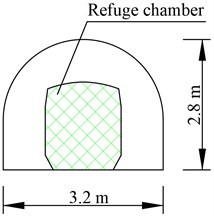
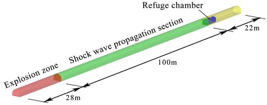
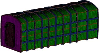
In the explosion experiment, a refuge chamber is placed in a full-size roadway, which is a semi-circular arch shape model with a length of 150 m, a height of 2.6 m and a width of 3.2 m, as shown in Fig. 1(a). The 28 m section in front of the roadway model is the gas/air mixture zone to simulate an explosion, and the length of the shock wave propagation section is 100 m. The refuge chamber model is placed at 22 m from the rear end in the roadway model [6, 23], as shown in Fig. 1(b). As mentioned above, two calculation methods were utilized to analyze the dynamic response of the refuge chamber.
Fig. 1a) Refuge chamber is placed in roadway model, b) flow field calculation model of refuge chamber
a)
b)
The first one is the direct coupling method. Models of the explosive, air, roadway and refuge chamber are combined into a united model. The shock wave is generated in front of the roadway model and it is propagated along with the entrained air to the refuge chamber model directly [21]. This method requires the grids between the fluid (e.g., air) and the solid (e.g., refuge chamber) elements must be connected [28], otherwise the impact loads cannot be transmitted to the refuge chamber model, causing an incorrect result. But the roadway model is far larger than the refuge chamber model, and the outer skin of the chamber is not smooth, which determined the two models cannot be meshed as a similar size. Thus, the refuge model chamber shall be significantly simplified. However, the combined model still consumes the calculation time greatly, and the result loses reference meanings.
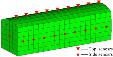
The other one is the indirect coupling method. Gas explosion and deformation of the refuge chamber are simulated separately. The processes are as follows. First, the combined model with roadway and refuge chamber models was established. As opposed to the direct coupling method, the refuge chamber model in a roadway is simplified to overcome the difficulty of connecting fluid and structure elements, as shown in Fig. 2(a). In this way, the refuge chamber models can be meshed with a large element size, and the element connection between the roadway and chambers elements is much easier. The impact loads are monitored by numerical sensors, which are set on different positions of the refuge chamber. Next, a detailed model of the refuge chamber is established, and the crucial parts are meshed with refinement (e.g., anti-explosion doors, flanges, glass and windows), as shown in Fig. 2(b). The materials and properties of models are set the same as the prototype chamber. Finally, the pressure-time curves are implemented to the detailed model to obtain the deformation.
Fig. 2a) Simplified model of refuge chamber and b) detailed model
a)
b)
The indirect coupling method extracts pressure-time curves and applies to the corresponding location of a detailed refuge chamber model, where the dynamic response of different parts can be clearly observed. Nevertheless, as discussed above, the simulation results are not verified by the experiment. Here, taking the indirect coupling method as the research object, three groups of physical experiments are conducted for comparing the corresponding simulation results.
3. Experimental system and calculation model
3.1. Experimental setup
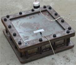
In the prototype chamber, the outer skin is made of Q235B low-carbon steel, which thickness is 6 mm, and the internal skeleton is made of steel rectangular tubes with a thickness of 3 mm, which forms a rectangular tube grid of 400 mm × 400 mm. Hence, the impact loads are resisted by the grids of combined outer skin with an internal steel skeleton. After weighing the feasibility against the complexity of an explosion experiment, a tube grid was taken as the experimental object.
The experiments were designed as follows. Three steel plates having the same material as the prototype chamber were constrained by a steel square frame. The impact loading was generated by the 8701 explosive [29], which were hung above the steel plates with different suspension distances. The detonation velocity and pressure of the 8701 explosive are 8315 m/s and 29.5 GPa, respectively. Three groups of experiments were carried out, and parameters are listed in Table 1.
Table 1Parameters of three groups of physical experiments
No. | Plate thickness (mm) | Explosive quantity (g) | Suspension distance (mm) |
I | 2.0 | 100 | 250 |
II | 1.0 | 200 | 500 |
III | 2.0 | 200 | 500 |
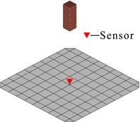
A pressure sensor was installed in the center of the steel plate to record the impact loading. The whole experiment is shown in Fig. 3(a).
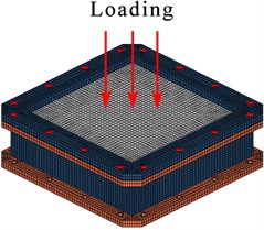
Fig. 3a) Figure of experiment model appearance, b) finite element model with big size element, where the air model was not shown, the pressure wave was monitored by the sensor, and c) detailed model with load applied on it
a)
b)
c)
3.2. Finite element model
According to the simulation processes of the indirect coupling method, the whole simulation process of the experiment was divided into three steps.
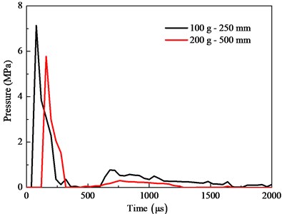
First of all, the models of plates, air and explosive were established according to the experiment, as shown in Fig. 3(b). The fluid-structure coupling algorithm was employed for the analysis of the explosive detonation, of which the ALE algorithm was used for simulating explosive and air [30, 31], and the Lagrange algorithm was used for a steel plate [32]. The peak pressure values in the experiment are the same as those of simulation, and the extracted pressure-time curves are shown in Fig. 4.
Fig. 4Pressure-time curves in two groups of simulation
Next, the detailed models were established, and the plate was meshed with elements size of 10 mm, as shown in Fig. 3(c). The SOLID164 and SHELL 163 units were used in flanges and plates, respectively. The steel material adopts the Piecewise_Linear_Plasticity model [23], and all parameters of different models were set the same as the prototype chamber (see Table 2). The total calculation time was 2000 μs, and time step was 10 μs.
Table 2Parameters of different models
Material | Density (kg/m3) | Elastic modulus (GPa) | Poisson’s ratio | Yield strength (MPa) | Ultimate strength (MPa) |
Q235B | 7800 | 206.8 | 0.3 | 235 | 441 |
Explosive | 1700 | 8.5 | − | − | − |
Air | 1.29 | − | − | − | − |
Then, the extracted pressure-time curves were applied to the detailed model, and the deformation of plates was measured.
4. Dimensional analysis
Through the indirect coupling method, the pressure-time curves on the different location of the refuge chamber are monitored by numerical sensors, as shown in Fig. 5.
Fig. 5a) Pressure-time curves calculated in roadway model by indirect coupling method [19]. Amount of pressure-time curves depending on that of numerical sensors and b) R1 and R2 curves as triangular waves [1, 27]
![a) Pressure-time curves calculated in roadway model by indirect coupling method [19]. Amount of pressure-time curves depending on that of numerical sensors and b) R1 and R2 curves as triangular waves [1, 27]](https://static-01.extrica.com/articles/21247/21247-img9.jpg)
a)
![a) Pressure-time curves calculated in roadway model by indirect coupling method [19]. Amount of pressure-time curves depending on that of numerical sensors and b) R1 and R2 curves as triangular waves [1, 27]](https://static-01.extrica.com/articles/21247/21247-img10.jpg)
b)
Considering Fig. 5, it becomes apparent that the shapes of monitored pressure-time curves are different from triangular waves. The difference between the direct coupling method and the indirect coupling method is that the latter extracts the pressure-time curves during the simulation process. A physical parameter, i.e., specific impulse, which describes the peak pressure, and the action time is introduced to verify the rationality of the extraction. The physical meaning of specific impulse is the impulse per unit area [33, 34], and the value is an area in the pressure-time curve [35].
In order to identify the effect of specific impulse extraction in deformation calculation, a dimensional analysis is made with the consideration of the specific impulse, and a theoretical model is established for calculating plate deformation.
For calculating the deformation of plates, an appropriate assumption for describing steel plate deformation behavior is proposed as necessary [36]. That is, the plate material is an ideal elastic-plastic material, and the explosion energy is entirely converted into the kinetic energy and plastic deformation energy of the plate. According to the mathematical statement of the plate deformation under an explosion [37, 38], the following dimensionless parameters can be identified:
where is the plate length, is the plate density, is the specific impulse, is the plate thickness, and is the yield stress of steel. Eq. (1) can be written as:
where is a dimensionless proportional coefficient, and is an undetermined constant.
The variables have dimensions , , , and . The value is expressed in terms of these variables:
Equating exponents on both sides, it has:
the solution is:
Then, substituting Eq. (5) into Eq. (2), it has:
where was proposed by Wang et al. [38], and Eq. (6) can be expressed as:
An empirical equation was proposed by Zhao [34], and was then used to solve the specific impulse generated by the explosive explosion:
where is the distance of the plate from the explosive center, is the quality of TNT explosive, and is the impulse correction coefficient. Eq. (7) can be expressed as:
The TNT equivalent ratio of 8701 explosive is 1.3, and when the TNT explosive exploded in the air, 225 [34].
5. Results and discussion
The experimental graphics and simulation cloud pictures are shown in Fig. 6. The maximum stress values of plates in groups I, II and III were 312.6, 374.7 and 282.5 MPa, respectively, which were less than the failure strength (411 MPa) of steel. No breakages were observed in the plates.
As Fig. 6 shows, the largest deformation occurred in the middle area of the plate. The difference between the experimental, simulation and Eq. (9) values is illustrated in Table 3.
Fig. 6a)-c) are experimental photos after explosion, and d)-f) are simulation results of plates
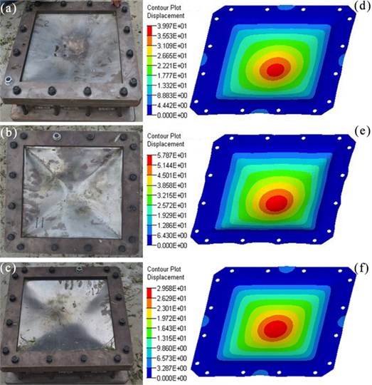
Table 3Maximum deformation values of experiments, simulation and Eq. (9).
Program | Experiment (mm) | Simulation (mm) | Eq. (9) (mm) | Error (%) |
Group I | 37.5 | 40.0 | 35.3 | 6.7 |
Group II | 52.2 | 57.9 | 55.9 | 10.9 |
Group III | 30.1 | 29.6 | 27.9 | 7.3 |
Note: The error is the maximum percentage value of two absolute ratios, where one is the ratio of the difference between simulation and experiment to experiment , and another is the ratio of the difference between Eq. (9) and experiment to experiment | ||||
The error, which maximum is about 10 %, shows that the numerical simulation results have a good agreement with the results of the experiment and Eq. (9). It indicates that the indirect coupling method simulates quite accurately the deformation process of the refuge chamber under an explosion.
The structure strength of a refuge chamber can also be optimized by the indirect coupling method. That is, the structure stiffness can be enhanced when the deformation in an area is larger than the design value. In contrast, it is weakened to reduce the weight and save costs.
6. Conclusions
1) An indirect coupling simulation method is utilized for analyzing the structure strength of a refuge chamber. In this method, an explosion is simulated in a roadway model, where the pressure-time curves on a simplified refuge chamber model are extracted and applied to a detailed model, which has the same materials and properties as the prototype chamber. Then, deformation is obtained for modification and optimization of the structure of the refuge chamber. The indirect coupling simulation method can be used to assess and optimize the structure strength of the refuge chamber in case of an explosion, saving the design time and test costs.
2) The simulation results calculated by the indirect coupling method fit well with the experimental and theoretical results, which demonstrate the reliability and validity of the indirect coupling simulation results.
3) In the indirect coupling method, the process of applying a pressure-time curve to the model is equivalent to the specific impulse on the prototype, which is the area encompassed by the pressure-time curve. As an empirical equation, Eq. (7) can be utilized to calculate the deformation of the steel plate under an explosion.
In a future research, a large-scale physical experiment is tested in the laboratory to further assess the reliability of results calculated by the indirect coupling method.
References
-
Wang L., Fan S., Gong J., Li J. Finite element analysis of antiknock performance for KJYF-96/8 refuge chamber. Coal Science and Technology, Vol. 42, Issue 3, 2014, p. 69-72, (in Chinese).
-
Margolis K. A., Westerman C. Y. K., Kowalski-Trakofler K. M. Underground mine refuge chamber expectations training: Program development and evaluation. Safety Science, Vol. 49, Issue 3, 2011, p. 522-530.
-
Yang X., Jin L., Li J. Explosion simulation and analysis of coal mine rescue capsule. Applied Mechanics and Materials, Vol. 143, 2012, p. 536-540.
-
Michael A. F. Parametric Design of a Coal Mine Refuge Chamber. Master’s Thesis, West Virginia University, 2007.
-
Refuge Alternatives for Underground Coal Mines: Final Rule. Mine Safety Health Administration, US Department of Labor, US Government Printing Office, Washington, DC, USA, 2008, p. 80656-80700.
-
Specifications for Coal Mine Mobile Refuge Chambers. China State Administration of Work Safety Printing Office, Beijing, China, 2014, p. 20-28.
-
Fan X. Study on blast performance of refuge chamber. Mining Safety and Environmental Protection, Vol. 37, 2010, p. 25-30, (in Chinese).
-
Dobashi R., Kawamura S., Kuwana K., Nakayama Y. Consequence analysis of blast wave from accidental gas explosions. Proceedings of the Combustion Institute, Vol. 33, Issue 2, 2011, p. 2295-2301.
-
Zhai C., Lin, B., Ye Q., Li X., Zhu C. Influence of geometry shape on gas explosion propagation laws in bend roadways. Procedia Earth and Planetary Science, Vol. 1, Issue 1, 2009, p. 193-198.
-
Mitchell M. D. Analysis of Underground Coal Mine Refuge Shelters. Master’s Thesis, West Virginia University, 2008.
-
Leblanc J., Shukla A. Dynamic response of curved composite panels to underwater explosive loading: Experimental and computational comparisons. Composite Structures, Vol. 93, Issue 11, 2011, p. 3072-3081.
-
Chapman T. C., Rose T. A., Smith P. D. Blast wave simulation using AUTODYN 2D: Parametric study. International Journal of Impact Engineering, Vol. 16, 1995, p. 777-787.
-
Chen Y., Hsiao C., Topacio A. Side resistance of drilled shafts socketed into rocks for serviceability and ultimate limit states. Advances in Technology Innovation, Vol. 5, Issue 3, 2020, p. 156-165.
-
Zhan Z., Jin L., Huang Z., Li Q. Research on waterproof and bearing pressure of refuge chamber. Journal of Central South University (Science and Technology), Vol. 47, Issue 3, 2016, p. 882-888, (in Chinese).
-
Li Q., Jin L., Niu J., Li J., Ping Y. Theoretical calculation and numerical simulation of waterproof refuge chamber shell. China Safety Science Journal, Vol. 24, Issue 1, 2014, p. 66-71, (in Chinese).
-
Ceng Y., Bai C., Li J., Chen J., Wang Z. Numerical simulation of rescue cabin under blasting in the tunnel. Journal of China Coal Society, Vol. 37, Issue 10, 2012, p. 1705-1708.
-
Zhao H., Qian X., Li J. Simulation analysis on structure safety of coal mine mobile refuge chamber under explosion load. Safety Science, Vol. 50, Issue 4, 2012, p. 674-678.
-
Yang J., Ma Y., Yang L., Zhang Z. Explosion-proof performance analysis of mine refuge chamber. Journal of China Coal Society, Vol. 38, Issue 1, 2013, p. 159-163, (in Chinese)
-
Wang L. Study of Cabin Structure and Gas Tightness of Mobile Refuge Chamber for Coal Mine under High Explosion Pressure. Master’s Thesis, China Coal Research Institute, 2014, (in Chinese).
-
Zhai X., Wu S., Wang K., Chen X., Li H. Novel design of rescue capsule considering pressure characteristics and thermal dynamic response with thermomechanical coupling action subjected to gas explosion load. Shock and Vibration, Vol. 2017, 2017, p. 5261309.
-
Li J., Tang Y., Liu X. Simulation analysis of mine refuge chamber performance in different loading modes. Explosion and Shock Waves, Vol. 37, 2017, p. 140-149, (in Chinese).
-
Zhang B., Zhao W., Wang W., Zhang X. Pressure characteristics and dynamic response of coal mine refuge chamber with underground gas explosion. Journal of Loss Prevention in the Process Industries, Vol. 30, 2014, p. 37-46.
-
Wang Y., Wang L., Qiu T., He C. Dynamic response analysis of mine-used mobile refuge supply chamber in gas and coal dust explosion. Safety in Coal Mines, Vol. 48, Issue 7, 2017, p. 107-109, (in Chinese).
-
Shi L., Li J., Wang C. Response characteristic research of shell structures under blasting. Explosive Materials, Vol. 43, Issue 5, 2014, p. 30-34, (in Chinese).
-
Li Z., Bai B., Xie Q., Wang Z., Cao S. Numerical simulation on dynamic response of movable mine rescue chamber subjected to impact loading. Journal of Vibration and Shock, Vol. 32, Issue 16, 2013, p. 146-151, (in Chinese).
-
Luo X., Qian X., Zhao H., Huang P. Simulation analysis on structure safety of refuge chamber door under explosion load. Procedia Engineering, Vol. 45, 2012, p. 923-929.
-
Meng Y., Li B., Wang Y. Structure design of new airtight blast door based on topology and shape optimization method. Geotechnical and Geological Engineering, Vol. 34, Issue 2, 2016, p. 703-711.
-
Macneal R. H., Harder R. L. Proposed standard set of problems to test finite element accuracy. Finite Elements in Analysis and Design, Vol. 1, Issue 1, 1985, p. 3-20.
-
Ramajeyathilagam K., Vendhan C.P., Rao V.B. Non-linear transient dynamic response of rectangular plates under shock loading. International Journal of Impact Engineering, Vol. 24, Issue 10, 2000, p. 999-1015.
-
Frei S., Richter T., Wick T. Long-term simulation of large deformation, mechano-chemical fluid-structure interactions in ALE and fully Eulerian coordinates. Journal of Computational Physics, Vol. 321, 2016, p. 874-891.
-
Khoei A., Anahid M., Shahim K. Extended arbitrary Lagrangian–Eulerian finite element method for large deformation of solid mechanics. Finite Elements in Analysis and Design, Vol. 44, Issues 6-7, 2008, p. 401-416.
-
Su D., Zheng D., Zhao L. Experimental study and numerical simulation of dynamic stress-strain of directional blasting with water jet assistance. Shock and Vibration, Vol. 2019, p. 2019, p. 1659175.
-
Tyas A., Warren J.A., Bennett T., Fay S. Prediction of clearing effects in far-field blast loading of finite targets. Shock Waves, Vol. 21, Issue 2, 2011, p. 111-119.
-
Zhao C. Study on Energy Output of Composite Explosive and Plastic Large Deformation Response of Target. Master’s Thesis, Nanjing University of Science and Technology, 2008, (in Chinese).
-
Wang H., Zha X., Yu M., Zhang M. Mechanical behavior of metallic sandwich panels under blast action. Journal of Building Structures, Vol. 34, 2013, p. 401-406.
-
Spranghers K., Vasilakos I., Lecompte D., Sol H., Vantomme J. Numerical simulation and experimental validation of the dynamic response of aluminum plates under free air explosions. International Journal of Impact Engineering, Vol. 54, 2013, p. 83-95.
-
Wang F., Feng S., Yu W. Study on large plastic deformation response of target plate under explosive blast wave. China Safety Science Journal, Vol. 3, 2003, p. 58-61, (in Chinese).
-
Jones N., Uran T. O., Tekin S. A. Dynamic plastic behavior of fully clamped rectangular plates. International Journal of Solids and Structures, Vol. 6, Issue 12, 1970, p. 1499-1512.
About this article

This research was supported by the Research Fund Project for Technology Innovation and Venture of China Coal Technology and Engineering Group (grant numbers 2018QN023 and 2018-TD-QN009), National Key R&D Program of China (grant numbers 2016YFC0600904 and 2016YFC0600801) and the China Scholarship Council (grant number 201808110255).
The authors would like to thank Shiping Fan, Jianping Li, Jianyu Gong, Long Shi, Chao He, Yiyi Hao, Yakun Zhang and Zhisheng Liu for the preparation of the explosion experiments.
