Abstract
One of the forefront of structural engineering is to realize the good resistance of building structure to earthquake loads. The performance philosophy of design structure has recently changed from preventing collapse to controlling the damage of structures under earthquake loading, which requires the development of new structural systems with great potential. An innovative multi-story suspended floors system model is proposed and its seismic responses are analytically studied in this paper to investigate the seismic performance of the system under strong earthquake loading. The system comprises a reinforced concrete frame with floors suspended from the columns using hangar rods. The characteristic of this suspended structure is that the lifting points of suspended floors are set on the columns. The equations of motion for this system are derived through the Lagrange equation and the structural responses are calculated in time-domain by the Newmark-beta method. A comparison between seismic responses of the innovative system and conventional frame system shows that the multi-story suspended floors system has excellent seismic performances. By establishing the relationship between the period ratio and seismic response of the system, the optimal period ratio is found to improve the seismic performance of the whole system. Finally, structural parameters such as the hangar rod length, damping ratio, and stiffness provided by the cushioning devices, the mass of suspended floors are optimized, considering seismic responses of rooftop and suspended floors as optimization objectives. It is shown that suitable parameters can be found to improve seismic performance and vibration control of the whole system.
1. Introduction
After more than 100 years of developments, seismic performance, especially the collapse resistant capacity, of conventional concrete structures, has been greatly improved. But in major earthquakes, such structures still suffer varying degrees of damage, and the repair costs of damage are an economic burden that can’t be ignored. To meet the seismic design performance objectives and to reduce the costs of post-earthquake repair, the development of new structural systems or seismic devices has become a hot topic in the field of civil engineering in recent decades [1-3]. These researches mainly focus on two directions: the one is to reduce the maximum inter-story displacement response of buildings so as to reduce the damage of structure; the other is to make damage or deformation of the structure occur in the certain assigned parts or devices which usually have strong deformation ability and are easy to repair, even to be replaced. These two directions are not irrelevant. For example, isolation technology [4] is used to concentrate structural deformation caused by an earthquake on the isolation story and reduce the story drift of the upper structure.
When some floors or equipment in a structure need to be specially protected, the floor isolation system (FIS) is proposed based on the base isolation technology and has been applied in practical engineering [5]. This system has been proved to be quite effective in reducing the seismic response of related floors and has also been tested by the actual earthquake [6]. For the sake of reducing seismic responses of the floors and the frame simultaneously, Hussam Mahmoud and Akshat Chulahwat [7] put forward the multi-suspended slab (MSS) applied to the frame on the basis of the FIS. Their research shows that the structure can effectively achieve the goal of mitigating seismic response of the floor and frame simultaneously, but the mitigating effect of the multi-story frame is not as good as high-rise structures (10 stories above).
In this study, the rigid joints interconnecting beams and columns are avoided to utilize as far as possible, and steel beams are used instead of concrete beams to reduce the floor weight. In the inelastic response of traditional concrete frames, the most dangerous failure modes are the failure of column ends and beam-column connection joints, while the ideal failure mode is the failure of beam ends. In fact, no matter which kind of damage mentioned above, the post-earthquake repair is not easy. Another disadvantage of concrete structures is that its higher mass increases the seismic force relative to steel structures. The Multi-story Suspended Floors system in this study is an improved structure to solve the above problems.
Owing to the suspended structure system [8] suspends some or all floors of structure with hanger rods or steel strands, the suspended floor tends to act as the mass block in TMD for low amplitude swing energy dissipation under earthquake loading, besides, suspended floor itself has the good self-centering ability, after the earthquake acceleration decreased to zero, suspended floor will automatically swing back to the initial position under the effect of gravity. In this paper, an innovative multi-story suspended floors system is proposed. Then, the equation of motion of the system is obtained by the Lagrange equation [9, 10] and is solved in Matlab [11, 12]. Afterward, a numerical example serves to illustrate the seismic performance of the multi-story suspended floors system. Then, the relationship between the period ratio and seismic responses of the system is established. Finally, the influence of parameters such as hangar rod length, the mass of the suspended floor, and the damping and stiffness provided by the cushioning device on the seismic response of the system is discussed.
2. Derivation of equation of motion
2.1. System description and simplification
The innovative multi-story suspended floors system model designed by our research group is given in Fig. 1. Different from the previous suspended structure system MSS, to prevent damage of beam-column joints, this system only retains the uninterrupted connection between rooftop beams and columns, and sets suspended floor’s suspension points on columns. Meanwhile, for the sake of reducing the undesirable effect of canceling some beam-column joints, cross-braces are installed between columns to maintain its stability. In addition, to enhance the self-centering ability of those suspended floors and energy dissipation ability of the system and to avoid the impact between suspended floors and columns during an earthquake, there are some viscoelastic cushioning devices at the edges of each suspended floor around the columns.
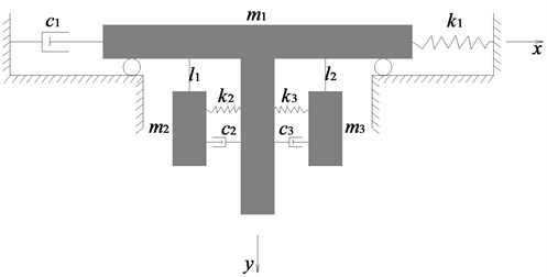
Considering the lateral seismic force acting on the structure, the roof and its supporting columns are closely connected and vibrate together. As the main structure, they can be regarded as a whole. Other suspended floors as tuned mass dampers are connected with the main structure by hanger rods at different heights of the supporting columns. Their vibration is relatively isolated from the main structure due to the action of hanger rods. Therefore, a single-degree-of-freedom system with attached multiple mass dampers is considered to represent the Multi-story Suspended Floors system. An idealization of the system with two suspended floors is shown in Fig. 2 in which those suspended floors are represented by two parallel lumped masses. Taking the idealized analytical model of a suspended two-story structure system as an example, the dynamic equations of motion for the suspended system are deduced based on the Lagrange equation.
The model comprises of mass that represents the equivalent mass of the main structure excluding the mass of those suspended floors, and (2, 3) represents the mass of the suspended floor. (2, 3) represents the length of the hanger rod or steel strand whose pendular angle is described by (2, 3). defines the rooftop’s lateral stiffness, which is equal to the horizontal force acting on the rooftop resulting in a unit horizontal displacement, and comprehensively reflects the effect of columns, beams, and cross-braces. is the damping corresponding to in the Rayleigh damping matrix obtained by taking a damping ratio of 0.05. (2, 3) and (2, 3) represent the cushioning device’s total damping and stiffness of each suspended floor (damping ratio varies between 0.07-0.15).
Fig. 1Structural model
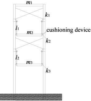
Fig. 2Simplified analysis model
2.2. Kinetic energy and potential energy of the system
As shown in Fig. 2, assuming the coordinate origin is at the center of in a static balance position, and the generalized coordinates of the system are described by , , . Because there are not many stories in this system, the lateral stiffness of column is evenly distributed along the vertical direction, and cross-braces are evenly installed on the upper part, it is assumed that the lateral displacement of the main structure without suspended part, when subjected to earthquake loading, is distributed like an inverted triangle shape. The displacement of is described by , and accordingly, the coordinates of and are , and , . where, and are the lengths of hanger rods that suspend and on the columns, respectively. In the following calculations, and temporarily take the same length.
The kinetic energy of the whole system can be expressed as:
The potential energy of the whole system can be expressed as:
where is the generalized force corresponding to the generalized coordinate (), damping forces(, , ) and inertial forces are no-potential forces, and their generalized forces corresponding to the generalized coordinates (, , ) are:
where is the ground acceleration.
2.3. Establishment of equations of motion
Partial potential Lagrange equation is:
where , respectively are the total kinetic energy and total potential energy of the whole system.
The motive equations of the system which is shown below in Eq. (5) can be obtained by substituting the Eqs. (1-3) into Eq. (4):
By trial calculations in Matlab, we found that the displacement responses of those suspended floors are small. In other words, the pendular angles of those floors are extremely small. When , ,…, are extremely small, we can assume: , , . The following equations are obtained by approximating the angular displacement related variables in the above equations:
The following matrix motion Eq. (7) is obtained from Eq. (6):
2.4. Feasibility of the method of solving the equations of motion
The Newmark-beta method [13] as a modification of the linear acceleration method is unconditionally stable when the parameter in its velocity and displacement expressions is greater than or equal to 0.25. In addition, the Newmark-beta method can be engaged to solve dynamic analysis problems of linear structures and non-linear structures. Therefore, the Newmark-beta method is selected to solve the equation of motion established in Section 2.3.
In this section, to validate the feasibility of the Newmark-beta method of solving Eq. (7), this method is used to obtain displacement responses of and that is compared with the corresponding responses calculated by Runge-Kutta method only considering the period ratio is changed with other parameters remain unchanged, and the results are shown in Fig. 3. The period ratio is defined as the following:
where is the period of the system corresponding to -th mode shape, and refers to the number of floors in the building. There is more discussion about the period ratio in Section 4.
Fig. 3Schematic diagram of the relationship between the period ratio and the displacement responses of m2 and m3 (m2, m3= 20032.08 kg, k2, k3= 10×104N/m, c2, c3 (damping ratio is 0.07), l1, l2= 1.8 m)
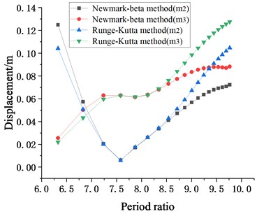
It can be seen from Fig. 3 that for , when the period ratio is between 6.75 and 8.75, the displacement response from the Newmark-beta method is in excellent agreement with that from the Runge-Kutta method; for , before period ratio increased to 8.75, the displacement response from the Newmark-beta method is in excellent agreement with that from the Runge-Kutta method. When the period ratio is greater than 8.75, the displacements of and calculated by the two methods are beginning to deviate. Generally speaking, as long as the range of the period ratio of the multi-story suspended floors system is well-chosen, we can obtain reasonable results of time history analysis of the seismic response by the Newmark-beta method, and the results are very valuable.
3. Numerical examples and analysis of calculation results
In order to simulate the dynamic response of the multi-story suspended floors system due to earthquake loading, a calculation model is developed according to Fig. 1, and dynamic response of the structure is obtained on the platform of Matlab. The parameters of the structural model are shown in Table 1. In the preliminary investigation of the system’s seismic performance, the length of hanger rods is 1.8 m considering that suspension points are at the midpoint of columns. To calculate the swing and self-centering processes of the suspended floors as a pendulum, the EL Centro seismic wave[14] with an amplitude of 0.4 g and duration of 30 seconds is input to the system, and zero seismic excitation of 10 s delay [15] is applied subsequently, so total earthquake duration is 40 seconds. In the Matlab environment, the Newmark-beta method is engaged to solve the seismic responses of this suspended system and conventional frame system with the same parameters, and those results are analyzed and compared. The calculation results are shown in Fig. 4.
Table 1Structural model parameter values
Parameter | Numerical value |
47957.28 kg | |
, | 20032.08 kg (12000 kg, 17116.08 kg, 20032.08 kg, 27000 kg) |
6584.362×104N/m | |
, | 10×104N/m (5-16×104N/m) |
The damping ratio is 0.05 | |
, | Damping ratio is 0.07 (0.07-0.15) |
, | 1.8 m (0.4-2.2 m) |
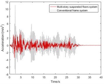
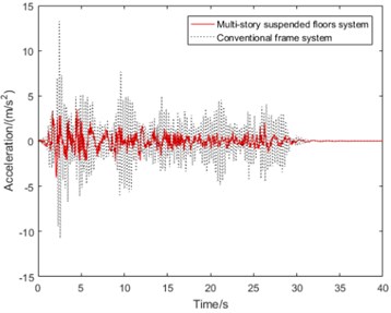
Fig. 4Comparison of seismic responses of multi-story suspended floors system and conventional frame system, (m2, m3 = 20032.08 kg, k2, k3= 10×104 N/m, c2, c3 (damping ratio is 0.07), l1, l2= 1.8 m)
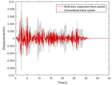
a) displacement
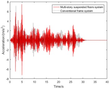
b) acceleration
c) acceleration
d) acceleration
It can be seen from Fig. 4(a), the peak displacement of multi-story suspended floors system’s is 5.73 mm while that of conventional frame system’s is 9.77 mm under major earthquake action, so the peak displacement of this suspended floors system’s is 41.35 % less than conventional frame structure, which shows that due to existence of suspended floors like TMD system, the deformation of the whole structure is significantly reduced, which is conducive to reducing column damage during earthquake. However, as shown in Fig. 4(b), the rooftop floor’s acceleration response is not much different from the conventional frame system.
It can be seen from Fig. 4(c) and (d) that acceleration responses of suspended floors are obviously suppressed compared with the conventional frame system, which is similar to the isolation system. After the earthquake excitation weakened, starting from about 26 seconds, the acceleration response of the suspended floor quickly winded down.
We believe that the suspended floor has a good self-centering capability, which is in line with the now widely accepted concept of innovative earthquake-resilient structure systems [1, 2]. As a result, the multi-story suspended floors system can achieve the expected vibration reduction control goal and has an excellent vibration reduction effect.
4. Analysis and optimization of structural parameters
It can be seen from the analysis results in Section 3 that the multi-story suspended floors system has good seismic performances. However, the dynamic characteristics of this system are affected by the length of hanger rods, the mass of suspended floors, the damping ratio and the stiffness provided by the cushioning device, etc. In this section, their influences of the above-mentioned system parameters on the seismic responses of the multi-story suspended floors system will be discussed.
Different hanger rod length and suspended floor mass will deduce different period ratio which is a dynamic index, so the period ratio is used as an important design parameter that is corresponding to the mode shape of the system and can affect the seismic response of the suspended system. In order to investigate the relationship between period ratio and seismic response of this suspended system, the period ratio corresponding to different hanger rod length is obtained using equation (7) and equation (8) first, and then the seismic responses of the suspended system with corresponding parameters are investigated.
4.1. Hanger rod length and period ratio
4.1.1. The relationship between hanger rod length and period ratio
Except for changing hanger rod length (0.4-2.2 m), other parameters are the same as those in Fig. 5. The period and mode shape of each order corresponding to each hangar rod length are obtained. The relationship between hangar rod length and period of each order is shown in Fig. 5, and the mode shapes of various orders corresponding to hangar rod lengths are listed in Table 2.
Fig. 5Schematic diagram of the relationship between hangar rod length and period of each vibration model, (m2, m3 = 20032.08 kg, k2, k3= 10×104 N/m, c2, c3 (damping ratio is 0.07), l1, l2= 0.4-2.2 m)
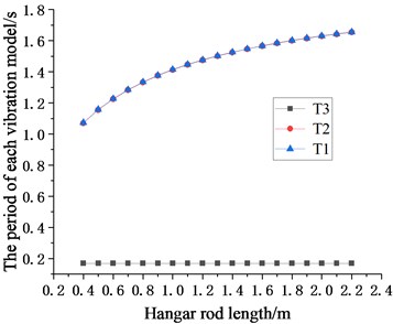
Table 2Mode shape of each order corresponding to each hangar rod length
Hanger rod length / m | First mode shape | Second mode shape | Third mode shape |
() = 0.4 m | 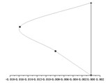 | 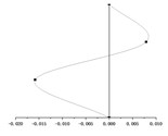 | 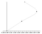 |
() = 0.5 m | 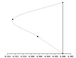 | 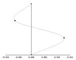 | 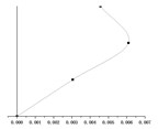 |
() = 0.7 m | 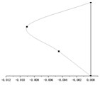 | 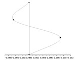 |  |
() = 0.9 m |  |  |  |
() = 1.0 m | 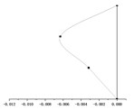 | 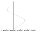 | 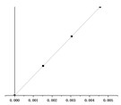 |
() = 1.5 m | 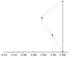 | 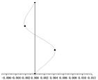 | 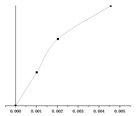 |
() = 2.0 m | 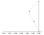 | 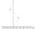 |  |
() = 2.2 m |  |  |  |
According to the equations of motion established in Section 2.3, the change of hanger rod length will affect the coefficient matrix in Eq. (7) and then affect the period value of each order. It can be seen from Fig. 5, with the same stiffness of the cushioning device, the periods of the first mode shape and the second mode shape ( and ) increase significantly with the increase of the hanger rod length, and the periods of the two modes are very close. However, the period of the third mode increases in this process slightly, which can be ignored. When and have the same value, the period of the first mode shape and the second mode shape is much longer than that of the third mode shape.
It can be seen from Fig. 5 that there is a one-to-one correspondence between hanger rod length and the period ratio of multi-story suspended floors structure system. As long as the corresponding relationship between hanger rod length and seismic response of multi-story suspended floors structure system is obtained, diagram of the relationship between the period ratio and seismic response of multi-story suspended floors structure system can be made.
It can be seen from Table 2 that the mode shapes of the multi-story suspended floors system are different from that of the classical structure system. Because the force transmitting pattern of the multi-story suspended floors structure system is different from that of the traditional system, the low-amplitude swing of the suspended floor under the action of an earthquake affects the distribution of mode shape. In addition, this system suspends one floor on each story, and in this case, all vertical columns will be subjected to the force from the cushioning devices at the height of the floor and the force from the hanger rods, which will also affect the mode shape.
By superimposing the mode shape of each order corresponding to each hanger rod length, it can be recognized that the displacement of the rooftop is very small, and the displacement of suspended floors and is large. This is consistent with the results of the smaller displacement seismic response of and the larger displacement seismic response of and obtained in the following section 4.1.2. Under earthquake loading, the the low-amplitude swing of the suspended floors and dissipate energy and reduce the seismic response of , and dynamic responses of the overall structural system also become smaller. Obviously, as the length of hanger rods increases, the vibration amplitude of and increases accordingly. Choosing the proper hanger rod length can control the seismic displacement response of and while achieving the goal of swing energy dissipation of suspended floors and improve the seismic performance of the whole structure.
4.1.2. The optimization of hanger rod length and period ratio
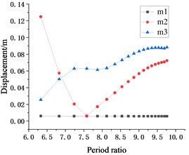
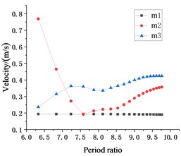
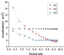
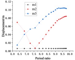
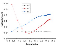
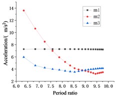
Except for changing hanger rod length (0.4-2.2 m), other parameters are the same as those in Fig. 6. The period ratio corresponding to each hanger rod length is calculated by Eq. (8) and maximum story displacement (m), maximum story velocity (m/s), maximum story acceleration (m/s2) of each story are obtained. The relationship between the period ratio of the system and seismic response of each floor under the action of two seismic waves, EL Centro wave and Taft wave, is given in Fig. 6.
It can be seen from Fig. 6, the trend of the relationship between the period ratio and seismic response of each story under the action of the EL Centro seismic wave is similar to the trend of the relationship between the period ratio and seismic response of each floor under the action of the Taft seismic wave. Under the action of the EL Centro seismic wave, as the period ratio increases, the displacement and velocity response of the suspended floor changes significantly, first decreases and then increases, while the overall displacement and velocity response of the suspended floor shows an increasing trend.
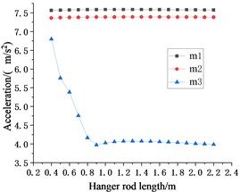
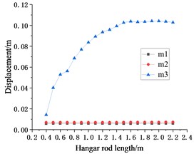
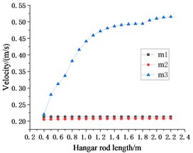
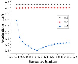
For displacement, velocity, and acceleration response, when the period ratio is small, the seismic responses of are larger than . This phenomenon indicates that the period ratio is too small to control the vibration of suspended floor . As for , the suspension point is lower and closer to the foundation, and its sensitivity to hanger rod length and the period ratio is far less than . Thus, with the increase of the period ratio, the displacement and velocity responses of are obviously changed, which all decrease first and then increase, while the displacement and velocity responses of keep increasing. After the period ratio reaches 6.83, the displacement response of starts and remains less than . Since then, there has been an extreme point where the smallest displacement and velocity responses happen to , and where acceleration is also not large. The optimal period ratio of is 7.58, and the corresponding hanger rod length is 0.7 m.
The relationship between the period ratio and the seismic response of each floor is similar under the action of two seismic waves. Moreover, as shown in Fig. 6(d), after the period ratio reaches 6.83, the displacement response of caused by seismic load also be less than that of , and the optimal period ratio is 7.58. If the hanger rods length of is changed separately, an optimal period ratio for may also be obtained.
From the overall view of Fig. 6, the modification of the period ratio has little influence on the seismic response of rooftop as the representative of the main structure. Generally speaking, choosing a proper period ratio can reduce the seismic response of suspended floors and the displacement response of the main structure, so that the seismic performance of the whole structure is better.
Fig. 6Schematic diagram of the relationship between period ratio and seismic responses of each story (m2, m3 = 20032.08 kg, k2, k3= 10×104 N/m, c2, c3 (damping ratio is 0.07), l1, l2= 0.4-2.2 m)
a) EL Centro wave displacement response
b) EL Centro wave velocity response
c) EL Centro wave acceleration response
d) Taft wave displacement response
e) Taft wave velocity response
f) Taft wave acceleration response
4.1.3. The further optimization of hanger rod length
It can be viewed from Section 4.1.2 that the seismic response control of the suspended floor is the best when is 0.7 m. However, in this case, the responses of are not synchronized to be optimized. In order to improve the overall seismic performance of this system, in this section, the length of the hanger rod of the suspended floor will be only changed within 0.4-2.2 m, while that of is always taken as 0.7 m. The values of other parameters are shown in Fig. 7. The Newmark-beta method is used to calculate the dynamic responses of these numerical models with various rod lengths. The maximum story displacement (m), the maximum story velocity (m/s), and the maximum story acceleration (m/s2) of each story are obtained. The relationship between the period ratio of the system and seismic response of each floor under the action of two seismic waves, EL Centro seismic wave and Taft seismic wave, is shown in Fig. 7.
Since the value of is always the optimal parameter value of 0.7 m, the seismic response of in Fig. 7 is similar to that of . With the change of , the seismic response fluctuations of and are extremely small and can be ignored.
Compared with the seismic responses caused by different waves to each other, it is found that when only changing the hanger rod , the overall change trend of the seismic responses of those floors is the same. Whether inputting the EL Centro seismic wave or Taft seismic wave to the system, the displacement and velocity responses of the structure increases with the increase of , while the acceleration response of the structure decreases with the increase of . Compared to the other two floors, the seismic response of the lowest floor makes it look as if this floor is isolated.
It can be concluded in Sections 4.1.2 and 4.1.3 that when and change between 0.4-2.2 m at the same time, the optimal parameter value of is 0.7 m. However, as can be seen from Fig. 7, under the action of two seismic waves, when is 0.7 m, the seismic responses of are not the minimum. As shown in Fig. 7(a) and Fig. 7(c), under the action of EL Centro seismic wave, when is 0.9 m, the displacement response of can get a smaller value and the acceleration response can get a minimum value. As Fig. 7(d) and Fig. 7(f) showing, under the action of the Taft seismic wave, the minimum acceleration seismic response can be obtained when is 1.1 m.
Based on the analysis and results above, whether it is to change the length of and synchronously or change the length of or independently, the displacement seismic response and velocity seismic response of show that the optimal length of is about 0.7 m. Although the seismic response of is greatly affected by seismic waves, considering the displacement and acceleration response of from Fig. 7, less than 1.1 m is more conducive to improving the overall seismic performance of the structure.
Fig. 7Schematic diagram of relationship between period ratio and seismic responses of each story (m2, m3 = 20032.08 kg, k2, k3= 10×104 N/m, c2, c3 (damping ratio is 0.07), l1= 0.7 m, l2= 0.4-2.2 m)
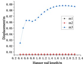
a) EL Centro wave displacement response
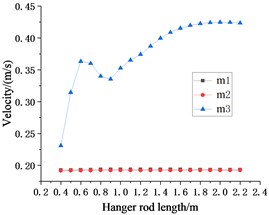
b) EL Centro wave velocity response
c) EL Centro wave acceleration response
d) Taft wave displacement response
e) Taft wave velocity response
f) Taft wave acceleration response
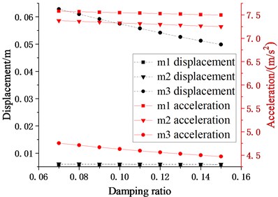
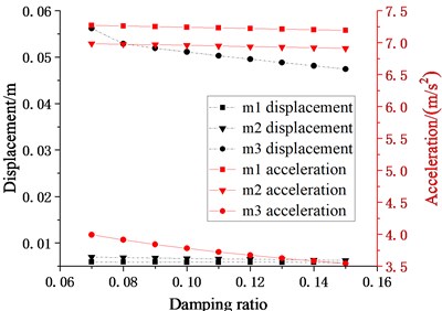
4.2. The damping ratio of cushioning device
As analyzed in Section 4.1, when the length of the hanger rod is 0.7 m, the seismic response of the overall structure is relatively small, so and in this section are taken to be 0.7 m. Except for changing the damping ratio (0.07-0.15), other parameters are the same as those in Fig. 8. The maximum story displacement (m), the maximum story velocity (m/s) and the maximum story acceleration (m/s2) of each story are obtained. Under the action of EL Centro and Taft seismic wave, the peak seismic responses of the structure with various damping ratio are plotted in Fig. 8.
Comparing the seismic response of the two waves shown in Fig. 8, it is found that under the action of two different seismic waves, when the damping ratio of the cushioning device changes within the range of 0.07 to 0.15, the trend characteristics of the maximum seismic response of the structure are similar. It can be seen from Fig. 8 that with the increasing of the damping ratio, the displacement response of decreases obviously. Under the action of two seismic waves, decreases from 62.82 mm to 49.85 mm and 56.18 mm to 47.44 mm, respectively 20.64 % and 15.55 %. The acceleration response of decreases at the same time, but the decreased amplitude is small, and the reductions under the action of two seismic waves are 6.36 % and 11.27 %, respectively. In this calculation, the length of the hanger rod is selected as the optimal value of obtained in the previous section, so the displacement response of is small, the reduction is extremely small, moreover, it is very close to the displacement response of , which is consistent with those responses at the optimal period ratio for in Fig. 6.
When each suspended floor adopts the same hanger rod, it can achieve ideal control for some suspended floors, while other floors can use damping ratio and other design parameters to improve the damping effect. Therefore, an increasing damping ratio of those feasible cushioning devices can effectively restrain displacement responses of to prevent it from colliding with the column. However, under the condition that the length of the hanger rod has been optimized, the change of the damping ratio of the cushioning devices has little effect on the displacement of .
As a result, increasing the damping ratio provided by cushioning devices can reduce the seismic response of suspended floors, and reduce the risk of the impact of suspended floors on columns, which can improve the seismic performance of the whole multi-story suspended floors system.
Fig. 8Schematic diagram of the relationship between damping ratio of cushioning device and seismic responses of each story (m2, m3 = 20032.08 kg, k2, k3= 10×104 N/m, c2, c3 (damping ratio is 0.07-0.15), l1, l2= 0.7 m)
a) EL Centro wave
b) Taft wave
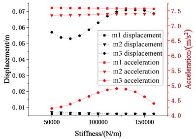
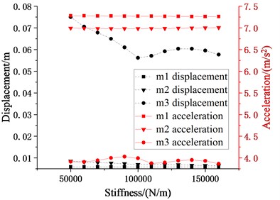
4.3. Stiffness of cushioning device
As analyzed in Section 4.1, when the length of the hanger rod is 0.7 m, the seismic response of the overall structure is relatively small, so and in this section are taken to be 0.7 m. Except for changing the stiffness (, : 5-16×104N/m), other parameters are presented in Fig. 9. The maximum story displacement (m), the maximum story velocity (m/s) and the maximum story acceleration (m/s2) of each story are obtained. Under the action of EL Centro and Taft seismic wave, the variation trend of various seismic responses of the structure with the change of stiffness is shown in Fig. 9.
It can be seen from Fig. 9 that with the increase of the stiffness of the cushioning devices, the displacement response of decreases first and then increases, and then decreases under the action of the two seismic waves, while the peak points are different. The effects of stiffness change of the cushioning devices on are different due to inputting different seismic waves. Under the action of the EL Centro seismic wave, the acceleration seismic response of increases first and then decreases. gets a smaller displacement and acceleration response when is equal to 7×10⁴N/m. Under the action of the Taft seismic wave, the acceleration response of shows its volatility with the increasing of stiffness . When is equal to 10×104N/m, smaller displacement and acceleration responses are obtained.
Fig. 9Schematic diagram of relationship between stiffness of cushioning device and seismic responses of each story (m2, m3 = 20032.08 kg, k2, k3= 5-16×104 N/m, c2, c3 (damping ratio is 0.07), l1, l2= 0.7 m)
a) EL Centro wave
b) Taft wave
Because the hanger rod length used for calculation is the hanger rod length corresponding to the optimal value of obtained in the previous section, so the displacement response of is small, the overall reduction is extremely small, and it is very close to the displacement response of . Since the cushioning device is installed at the edges of each suspended floor, the peak displacement and acceleration responses of which represents the main structure don’t change greatly with the change of the stiffness of the cushioning devices.
From the response of in Fig. 9, the influence of the stiffness of cushioning devices on the suspended floor can’t be ignored, and there may be an optimal stiffness or an unfavorable stiffness values that may increase the structural response. The reasonable value of stiffness is also related to the input seismic waves. If the stiffness of the cushioning device is too low, the displacement of the suspended floor can’t be limited. If the stiffness of the cushioning device is too large, the displacement of is too small, and the swinging energy dissipation characteristics of the suspended floor will not work. It can also be noted that the influence of the hanger rod length on the seismic response of the higher suspended floor is more decisive than other design parameters.
4.4. Mass of suspended floor
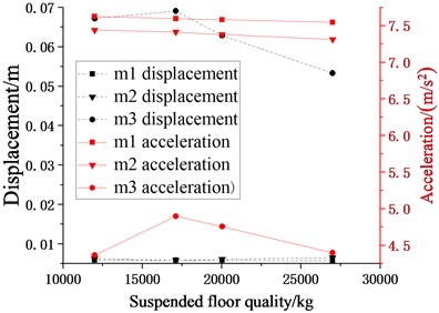
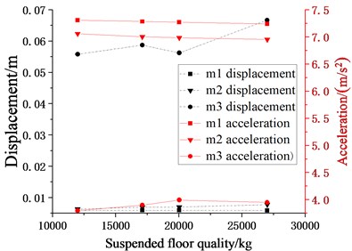
In the TMD system, the suspended mass is an important design parameter, which has obvious influence on system performance. In this section, except for changing the mass of suspended floors (12000 kg, 17116.08 kg, 20032.08 kg, 27000 kg), other parameters are listed in Fig. 10. Maximum story displacement (m), maximum story velocity (m/s) and maximum story acceleration (m/s2) of each story are obtained. Under the action of EL Centro and Taft seismic wave, the variation trend of various seismic responses of the structure with the change of the mass of suspended floors is illustrated in Fig. 10.
When the input seismic waves are different, the results of the structural seismic response also vary greatly. It can be seen from Fig. 10 that the change of seismic wave has a greater impact on the displacement and acceleration seismic response of . Under the action of EL Centro seismic wave, the changing trend of acceleration response increases first and then decreases. When the mass of the suspended floor is 17116.08 kg, the acceleration response is the largest. However, under the action of the Taft seismic wave, the minimum displacement response of can be obtained when the mass of the suspended floor is 20032.08 kg. While comparing the figure on the left, it is found that under the action of the EL Centro seismic wave, the displacement response of isn’t the minimum when the mass of the suspended floor is 20032.08 kg.
Fig. 10Schematic diagram of relationship between suspended floor quality and seismic responses of each story (m2, m3 = 12000 kg, 17116.08 kg, 20032.08 kg, k2, k3= 10×104 N/m, c2, c3 (damping ratio is 0.07), l1, l2= 0.7 m)
a) EL Centro wave
b) Taft wave
It can be concluded that the change of the mass of suspended floors has a great impact on its displacement and acceleration responses, so the selection of the quality of suspended floors is important to its own seismic response. Because the hanger rod length used for calculation is the optimal value of in the previous section, so the displacement response of is small, the overall reduction is extremely small, and it is very close to the displacement response of . Fig. 10 also shows that with the increase of the mass of the suspended floor, the displacement response of is also reduced, but the amplitude is smaller.
From the results of this study, it is an alternative method to improve structural performance by adjusting the additional weight of the floor. Although it is difficult to affirm the actual mass of each floor precisely, as long as the inclusiveness of the design value is considered in advance and the actual value has a certain range, well seismic performance can be achieved.
5. Conclusions
In this study, an innovative multi-story suspended floors system is proposed, which is on the basis of the floor isolation system and multi-story suspended slabs system. The seismic response of a numerical model of this innovative system in which the same design parameters are employed to each suspended floor has been analyzed and compared with a conventional frame system under a major earthquake. The following observations and conclusions can be drawn from the present study.
1) Before the parameter optimization, the displacement reduction ratio has reached 41.35 %, which shows that the seismic response of the main structure is obviously restrained due to the existence of the suspended floors. Moreover, acceleration responses of the suspended floors are obviously mitigated compared with the conventional frame system. The results show that the vibration damping effect of the multi-story suspended floors structure system is obvious.
2) With regard to the multi-story suspended floors system, the parameter setting is very significant. The calculation results show that there is an optimal period ratio, and a reasonable and appropriate selection of period ratio can minimize the seismic response of the whole structure. It can also be inferred that if different suspended floors adopt different hanger rod lengths, better seismic responses may be obtained.
3) Because the displacement response of suspended floors is larger than that of the conventional frame system, it is necessary to set cushioning devices at the edges of each suspended floor. The cushioning device provides damping energy dissipation and stiffness to limit displacement of the suspended floor, which can greatly reduce the seismic response of the suspended floor and significantly improve the seismic performance of the whole multi-story suspended floors structure system.
References
-
Lu X. L., Zhou Y., Chen C. Research progress on innovative earthquake-resilient structural systems. Earthquake Engineering and Engineering Vibration, Vol. 34, Issue 4, 2014, p. 130-139.
-
Lu X. L., Chen Y., Mao Y. J. New concept of structural seismic design: earthquake resilient structures. Journal of Tongji University (Natural Science), Vol. 39, Issue 7, 2011, p. 941-948.
-
Chen Y. Y., Chen K., Tan P. P. A study on structural seismic control performance by nonlinear energy sinks with negative stiffness. Engineering Mechanics, Vol. 36, Issue 3, 2019, p. 149-158.
-
Du D. S., Wang S. G., Liu W. Q., et al. Reliability-based damage performance of base-isolated structures. Journal of Vibration and Shock, Vol. 35, Issue 1, 2016, p. 222-227.
-
Kaneko M., Yasui Y., Okuda Y. Simultaneous horizontal and vertical vibration tests of three-dimensional floor isolation system. AIJ Journal of Technology and Design, Vol. 1, Issue 1, 1995, p. 186-90.
-
Cui S., Bruneau M., Kasalanati A. Behavior of bidirectional spring unit in isolated floor systems. Structural Engineering, Vol. 136, Issue 8, 2010, p. 944-952.
-
Mahmoud H., Chulahwat A. Response of building systems with suspended floor slabs under dynamic excitations. Engineering Structures, Vol. 104, 2015, p. 155-173.
-
Jin W. L. Theory of Suspended Structures: Wide Application of Universal Variational Principle. Zhejiang Science and Technology Press, 1981, (in Chinese).
-
Wang G. Y. Applied Analytical Dynamics. People’s Education Press, 1981, (in Chinese).
-
Zhang C., Li L., Ou J. Swinging motion control of suspended structures: principles and applications. Structural Control Health Monitoring, Vol. 17, Issue 5, 2010, p. 549-562.
-
Dang Y., Han J. P., et al. Dynamic analysis of structures with Matlab. Science Press, 2014, (in Chinese).
-
Zhao Y. S., Cheng Y. L. Tunnel test analysis of the high-rise suspended structure damping system. Industrial Construction, Vol. 30, Issue 4, 2000, p. 31-33.
-
Li H. J., Wang T., Liao X. An interpretation on Newmark-β methods in mechanism of numerical analysis. Earthquake Engineering and Engineering Vibration, Vol. 31, Issue 2, 2011, p. 55-62.
-
Zhang R., Li H. N., Wang D. S., et al. Selection and scaling of real accelerograms as input to time-history analysis of structures: a state-of-the art review. Engineering Mechanics, Vol. 36, Issue 2, 2019, p. 4-19.
-
Jiang W. B., Hu X. B., Hao T. Study of residual displacement of reinforced concrete frame structures under strong earthquake. Engineering Journal of Wuhan University, Vol. 50, Issue 6, 2017, p. 842-849.
Cited by
About this article

The research was financially supported by the Gansu Natural Science Foundation Project (Grant No. 2017GS10839).
