Abstract
To enhance the compression performance and improve the paving quality of the VSS of the pavers, the experimental research of the VSS is performed to assess the VSS’s vibration stability under various excitations of the tampers and vibrator screed. A VSS’s dynamic model is also established to simulate and evaluate the VSS’s working performance. The root-mean-square (RMS) acceleration responses of the vertical and pitching motions at centre of gravity of the screed floor are chosen as the objective functions. In order to increase the VSS’s working performance, the dynamic parameters of the angular deviations of tampers are then controlled based on Fuzzy control. The research results indicate that the RMS value of the vertical screed motion is remarkably increased, concurrently the RMS value of the pitching screed angle is significantly reduced by controlling the angular deviations of tampers under different excitation frequencies of the VSS. Therefore, the VSS’s working performance is significantly improved in comparison without the control of the angular deviations.
Highlights
- Improve the paving quality of the vibration screed system (VSS) is researched based on the optimal fuzzy control
- The research results have been determined via the experimental research of the VSS
- Results: the RMS value of the pitching screed angle is significantly reduced by controlling the angular deviations of tampers under different excitation frequencies of the VSS
- Results: the VSS’s working performance is significantly improved in comparison without the control of the angular deviations
- Application: Result can also be referenced to control the compaction force of soil compactors, which has not yet been considered in existing publications, to enhance vehicle's performance
1. Introduction
The vibratory screed system (VSS) of the pavers was used to pave uniformly and rapidly the asphalt mixture on the pavements. Thus, the VSS was designed by using a pair of tampers and a screed floor. The tampers were applied to compress the asphalt mixture on the pavements to obtain more uniform and tighter densities. Meanwhile, the screed floor with a width of 9 or 12 m was used to improve the smooth pavement in the paving process [1-3], as shown in Fig. 1(a). Therefore, VSS’s working performance was mainly evaluated via compression performance and paving quality [4, 5].
To analyze the compression performance of the VSS, the influence of the interaction between the compression force of tampers, mix-asphalt material, and elastoplastic ground on the VSS’s compression performance had been analyzed by some researchers [5-9]. It was found that the compression performance was mainly affected by mix-asphalt material when the elastoplastic ground obtained with its high-density. Thus, the characteristics of the mix-asphalt material were studied. The influence of the size of particles, temperature, and density of the mix-asphalt material was analyzed under the excitation of tampers [7, 10, 11]. The Fuzzy technique, compaction monitoring system, and multi-sensor infrared temperature scanning bar system were also applied to reduce the error of the unequal converge and optimize the compression density of the mix-asphalt material, respectively [8, 12, 13]. The research results indicated that the maximum compression performance could be achieved by using hot mix-asphalt under high and stable amplitude compressive forces of tampers. However, the research results also showed that the compression force of tampers was greatly affected by the dynamic parameters of the VSS, such as the excitation frequencies of tampers and vibrator screed, angular deviations of tampers, and distance of eccentric configuration of tampers [4, 6, 14, 15]. The vibration excitations of the VSS, the mass of tampers, and eccentric distance of the eccentric shafts were then optimized to improve the compression performance, respectively [3, 4, 16]. These dynamic parameters were then optimized, the optimal results showed that the maximum compression performance was obtained under the excitation frequencies of tampers () from 10 Hz to 20 Hz and vibrator screed () from 30 Hz to 40 Hz, especially at 15 Hz and 32 Hz. However, the results also indicated that the VSS’s shaking was the maximum at these excitation frequencies. Therefore, the paving quality of the VSS was strongly decreased. To reduce the VSS’s shaking, the angular deviations between adjacent tampers of the front and rear tampers (), between right and left tampers (), and between the front and rear tampers () were analyzed and optimized [4, 18]. The paving quality was then significantly improved. Although the researches had not yet considered under various excitation frequencies of both and , the conclusion of the researches indicated that controlling the angular deviations of the tampers could optimize the VSS’s working performance under different excitations of and .
In this study, to further enhance the compression performance and improve the paving quality of the VSS, the VSS’s working performance is researched via the experiment under various excitations of the tampers and vibrator screed. A VSS dynamic model is then established to simulate and evaluate the VSS’s vibration stability. The compression performance and paving quality are chosen as two indexes to evaluate the VSS’s working performance based on the objective functions of the RMS acceleration responses of the vertical and pitching screed motions. Based on the MATLAB/Simulink software and its Fuzzy control tools, the VSS dynamic model and angular deviations of tampers are then designed and controlled to enhance the compression performance and improve the paving quality of the VSS.
2. Experimental research of the VSS
2.1. Set-up of the test model
The vibration screed system includes eight couples of tampers excited by the vibration frequency () of the tampers to compact the asphalt pavements and a screed floor excited by the mass of the eccentric configuration of the vibrator screed with the excitation frequency () to smooth the asphalt pavements.
In order to investigate the VSS’s stability and paving efficiency, the experiment of the VSS is made under different excitation frequencies of tampers and vibrator screed to measure the vertical acceleration responses and their RMS values on the screed floor. The testing process is as follows: a vibration screed system with its width 12m is used for the experiment. Accelerometers ICP® and an analysis system of Belgium LMS are applied to measure and compute the vertical acceleration responses and their RMS values on the screed floor. There are 24 sensors in which 12 sensors are installed in the front screed floor and 12 sensors are installed on the rear screed floor to determine the acceleration response at measurement points. The model of the test set-up is detailed in Fig. 1.
The measurement process is made under the different excitation frequencies of {10 %, 20 %,..., 100 %}× corresponding to two different excitation frequencies of {0 %, 50 %}×. Herein, 21 Hz and 45 Hz determined based on the actual parameters of the maximum angular velocities of tampers 1250 rpm and vibrator screed 2700 rpm of the VSS are the maximum excitation frequencies of the tampers and vibrator screed, respectively. It can also be simply described based on the and as follows:
Based on the measured data of the vertical acceleration responses at measurement points, their RMS values are computed via the signal processor and then displayed.
In previous studies of the VSS experiment, the acceleration response of the screed floor had only tested at three different locations on the screed floor [14] or at each measurement position [1] to evaluate the influence of the excitation frequencies of the tampers on the VSS’s stability. The above methods are simple for the experiment but difficult to accurately reflect the VSS’s stability due to the width of VSS up to 12 m. In this test method, the RMS acceleration responses at various measurement positions can be simultaneously determined, thus, the VSS’s stability and paving efficiency are easily analyzed compared with the existed researches.
Fig. 1Structure of VSS and its experimental set-up
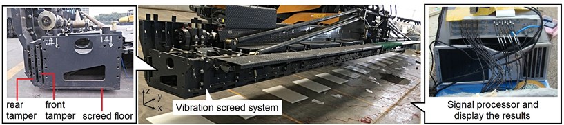
a) Experimental set-up
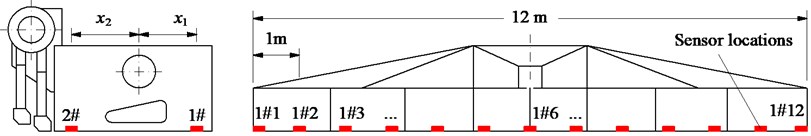
b) Experimental model
2.2. Discussion of test results
Based on the measured results of the RMS acceleration responses at measurement points i on the front and rear screed floors ( and ), the RMS values at centre of gravity of the screed following the screed width are calculated by:
where and are the distances from the centre of gravity of the screed to measurement points at front and rear screed floors in the -direction, 1, 2, ..., 12.
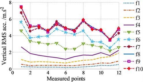
The RMS accelerations under the different excitation frequencies of tampers in two cases of Eq. (1) without screed excitation ( 0 Hz) and (2) with screed excitation ( 22.5 Hz) are plotted in Figs. 2(a)-(b).
(1) Without the screed excitation ( 0 Hz), the results in Fig. 2(a) show that the RMS accelerations on the screed width are relatively symmetrical and uniform under excitations of . It means that the smoothness of the pavement surface is good and the paving quality is improved. However, the obtained RMS values are relatively small, thus, the compression performance is low and the asphalt density may be reduced and not uniformed.
When increasing the excitations of , the RMS results are quickly increased. The VSS’s compression performance is thus enhanced, especially at 14.7 Hz. But the paving quality is strongly reduced due to uneven distribution of accelerations on the screed floor under the impact of .
When increasing the excitations of , the measured results show that the RMS values are insignificantly increased while the RMS values between the tested locations are still greatly skewed, therefore, the working performance of the VSS are insignificantly improved under the excitations of .
Fig. 2Experimental results under various frequency excitations of the VSS
a) Without screed excitation ( 0 Hz)
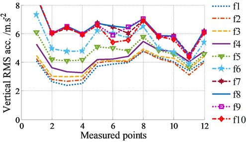
b) With screed excitation ( 22.5 Hz)
(2) With the screed excitation ( 22.5 Hz) added to the VSS, Fig. 2(b) indicates that the influence of the various excitation frequencies of tampers on the RMS accelerations of the screed floor is similar to the results without the screed excitation. However, due to the influence of the screed excitation , the RMS accelerations at the tested locations are remarkably skewed and increased in comparison with the results of without the screed excitation, especially under excitations of .
Based on the experimental analysis of the VSS, it can see that the excitation frequencies of both and strongly affect the VSS’s working performance. The VSS’s compression performance is maximum at or while the paving quality is greatly reduced at these frequencies. It is very difficult to obtain simultaneous both increasing the compression efficiency and improving the paving quality under the various excitations of both and .
The research results in Refs. [2, 5] also showed that the asphalts paver’s performance is affected not only by the vibration excitations of and but also by the angular deviations of the tampers. Thus, in order to improve the VSS’s working performance, a VSS’s dynamic model is established to control the vibration of tampers under the various excitations of and .
3. Dynamic model and vibration control of VSS
3.1. The vibration dynamic model of VSS
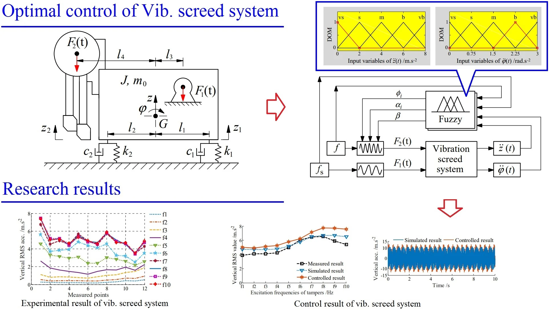
In order to study vibration and control the VSS, its mathematical model should be set-up to calculate vibration equations. Based on the VSS’s structure in Fig. 1(a), a dynamic model of the VSS is then built as in Fig. 3(a) to research the vibration characteristics of the VSS, where and are the mass and moment of inertia of the screed. and are vertical and angular displacements at centre of gravity of the screed. and are the damping and stiffness parameters of the asphalt pavement under the screed floor. and are the vibration excitation forces of the screed and tamper of the VSS. and are the distances from centre of gravity of the screed to the location of vibration isolations and vibration excitations, respectively.
Fig. 3The dynamic model and vibration excitation model of the vibration screed system
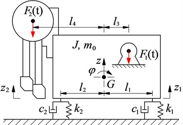
a) VSS’s dynamic model
b) Vibration excitation of tampers
Based on the dynamic model in Fig. 3(a) and application of Newton’s second law, the dynamic differential equation for the VSS is given by the following matrix form:
The vibration excitation forces of the vibrator screed and tampers in the -direction are respectively calculated as follows:
where , , and are the mass, distance of eccentric configuration, and vibration excitation frequency of the vibrator screed, respectively. is the vibration excitation force of tamper in the -direction.
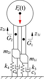
To determine the of tamper , the dynamic model of tampers is then established as in Fig. 3(b). Where and and are the vertical displacements and masses at centre of gravity of the front and rear tampers . and are the damping and stiffness parameters of the asphalt pavement under the front and rear tampers, (1, 2,..., 8).
Based on the dynamic model in Fig. 3(b) and also application of Newton’s second law, the equation of the excitation force of the tampers is determined as:
where then ; then . and are the distance of the eccentric configuration of the front and rear tampers. is the vibration excitation frequency of tampers. is the angular deviation between adjacent tampers of the front and rear tampers. is the angular deviation between the right tampers, 1,2,3,4, and left tampers, 5,6,7,8. is the angular deviation between the front and rear tampers, 90°.
The excitation forces of the VSS in Eq. (4) are then applied to simulate the vertical and pitching acceleration responses at centre of gravity of the screed.
3.2. Evaluation index of VSS’s working performance
The influence of the vibration excitations and on the VSS’s working performance is evaluated via the vertical RMS accelerations of the screed floor in the experimental part. To evaluate the VSS’s compression performance and paving quality, the RMS acceleration responses of the vertical screed motion and pitching screed angle at centre of gravity of the screed are chosen as the evaluation indexes and described as follows:
where and is the acceleration responses of the vertical screed motion and pitching screed angle at centre of gravity of the screed in the simulation time of .
Therefore, to increase compression performance and improve the paving quality of the VSS, the increase of and reduction of are the objective functions.
3.3. Design of fuzzy control for the VSS
3.3.1. VSS’s control model
The VSS’s working performance is mainly dependent on the vibration excitations of and of the vibrator screed and tampers, as described in Eq. (4). Meanwhile, is greatly affected by the dynamic parameters of angular deviations of {, , and } part from the excitation frequency () of tampers [2, 5]. In the working process of the VSS, both and frequencies can be changed and depend on the VSS’s operator, while parameters of {, , and } are unchanged according to the original design. In order to increase compression performance and improve the paving quality of the VSS, the compression acceleration in the -direction needs to be increased, concurrently the VSS shaking should be minimized. Therefore, the angular deviation parameters of {, , and } in Eq. (5) should be controlled based on the change of the excitation frequencies {, } and feedback accelerations {, }.
The vibration control methods such as PID control, Fuzzy control, control, PID-Neural, Skyhook-Fuzzy, or PID-Fuzzy control [8, 18, 19] have been applied to control the mechanical vibration systems or vehicle suspension systems. The used control methods depend on the various control objects of each system. Fuzz control is the controller that does not depend on the operating conditions of the control system. It only depends on the appropriate selection of the control rules in the fuzzy inference system (FIS). Particularly, Fuzz control has the ability to control multi-objective based on its FIS [18, 20]. Based on the multi-objective functions of this study, Fuzzy control can be suitable to control the VSS’s vibrations.
To control the VSS’s vibrations, Fuzzy control is then used to calculate the optimal dynamic parameters of {, , and } based on four signals of the excitation frequencies {, }, acceleration responses of the vertical motion, and of pitching angle at centre of gravity of the screed {, }. Its control system model has been given in Fig. 4.
Fig. 4VSS’s control model with Fuzzy control
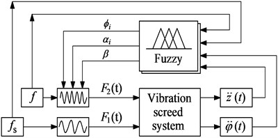
Fig. 5In-output variables of membership function
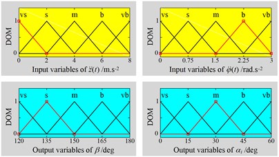
3.3.2. Fuzzy control and application
Based on the research results of the influence of the angular deviations on the VSS’s working performance [1, 4], it was found that the compression performance and paving quality were significantly improved with 60°, 60°, and 120°. Thus, based on the experimental results of the influence of the excitation frequencies {, } on the VSS’s working performance in Section 2.2, the boundary conditions of the control parameters are defined by:
The angular deviation parameters are then controlled based on Fuzzy control.
In Fuzzy control, there are three basic parts of the fuzzification interface, FIS, and defuzzification interface. Its control principle consists of the following steps: First, the input parameters are transformed into input linguistic variables via the fuzzification interface, then, input linguistic variables are deduced into output linguistic variables through FIS, and finally, the output linguistic variables are transformed back to output parameters via defuzzification interface [21]. According to the control model described in Fig. 4, four input values of {, , , and } and three values of {, , and } are used for Fuzzy control, respectively. However, the 60° is defined with the initial parameter of the system, thus, their in-output variables of membership function in FIS are given in Fig. 5 based on the boundary conditions in Eq. (7).
Fig. 5, in-output linguistic variables are defined by very small (vs), small (s), medium (m), big (b), and very big (vb), respectively. The shape of membership functions is used by the triangular function and the value of the degree of memberships (DOM) is between 0 and 1.
With the FIS of Fuzzy control, “If-then” rules are then built to describe the relationship between in-output language variables based on the boundary conditions of the control model and the experience of the designer. In this study, fifty control rules are given in Tables 1 and 2 and described as follows:
(1) IF 0 ≤ ≤ 10.5 and 0 ≤ ≤ 22.5Hz, is "vs", is "vs" THEN is "vs" and is "vs";
(2) IF 0 ≤ ≤ 10.5 and 0 ≤ ≤ 22.5Hz, is "s", is "vs" THEN is "s" and is "vs";
...
(50) IF 10.5 < ≤ 21 and/or 22.5 < ≤ 45Hz, is "vb", is "vb" THEN is "vb" and is "b".
The centroid method and minimum function in FIS of Fuzzy control [20] are then used to calculate the output values via if-then rules.
Table 1The FIS’s rules with 0 ≤ f ≤ 10.5 and 0 ≤ fs ≤ 22.5 Hz
Control rules | |||||||||||
vs | s | m | b | vb | vs | s | m | b | vb | ||
vs | vs | s | s | m | m | vs | vs | s | s | m | |
s | s | s | s | m | m | vs | s | s | s | m | |
m | s | s | m | m | m | s | s | m | m | m | |
b | m | m | m | m | m | s | s | m | m | m | |
vb | m | m | m | m | m | m | m | m | m | m | |
Table 2The FIS’s rules with 10.5 < f ≤ 21 and/or 22.5 < fs ≤ 45 Hz
Control rules | |||||||||||
vs | s | m | b | vb | vs | s | m | b | vb | ||
vs | m | m | m | b | vb | m | m | b | b | b | |
s | m | b | b | b | vb | m | m | b | vb | b | |
m | m | b | b | b | vb | b | b | vb | vb | b | |
b | b | b | b | vb | vb | b | vb | vb | vb | b | |
vb | vb | vb | vb | vb | vb | b | b | b | b | b | |
Table 3Major parameters of the vibration screed system
Parameter | Value | Parameter | Value | Parameter | Value |
(kg) | 3 083 | (kg) | 69 | (m) | 0.332 |
(kg) | 78 | (kg) | 72 | (m) | 0.163 |
(kg) | 80 | (kNs m-1) | 58 | (m) | 0.114 |
(kg) | 110 | (kNs m-1) | 68 | (m) | 0.2 |
(kg) | 114 | (Ns m-1) | 0 | (m) | 0.003 |
(kg) | 70 | (kN m-1) | 3 570 | (m) | 0.003 |
(kg) | 71 | (kN m-1) | 3 060 | (m) | 0.0025 |
4. Control results
Based on the actual structure parameters listed in Table 3, MATLAB/Simulink is applied to simulate the VSS’s dynamic equations under various vibration excitations of tampers () at two cases of 0 Hz and 22.5 Hz. The Fuzzy control tools in MATLAB are then designed and developed to control the vibration screed system based on the boundary conditions in Eq. (7) and control rules in Tables 1 and 2.
4.1. Without the excitation of vibrator screed
The simulation results of the acceleration responses of the vertical and pitching screed motions under excitation of 10.5 Hz and without are plotted in Figs. 6(a)-(b). The controlled results show that the vertical screed acceleration is increased, concurrently the pitching screed acceleration is reduced in comparison with that of the simulated results without control. This means that the VSS’s working performance is significantly improved under an excitation 10.5 Hz of tampers.
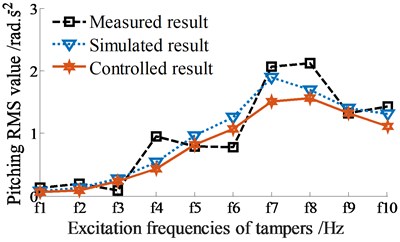
The control performance is then evaluated under various excitation frequencies of tampers, 0 ≤ ≤ 21 Hz. The measured, simulated, and controlled results of the RMS accelerations of the vertical and pitching screed motions are shown in Figs. 7(a)-(b), respectively.
Under the same experimental condition, the simulated and measured results without control show that the curves of the RMS values of the vertical and pitching RMS values at centre of gravity of the screed with simulation are similar to that of measurement. The small error between the simulated and measured values can be due to the influence of the engine vibration and error of the VSS parameters. However, the error between the measured and simulated values is negligible. Therefore, this implies that the mathematical model with the parameters of the VSS is accurate and feasible, and it is used to simulate and analyze the control results.
Fig. 6Acceleration responses at centre of gravity of screed without excitation of fs1 (fs1= 0 Hz)
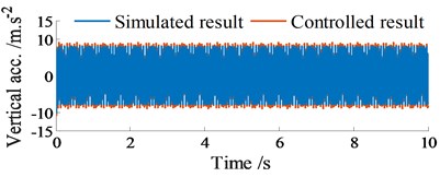
a) Vibration of screed heave at 10.5 Hz
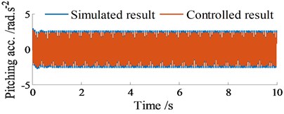
b) Vibration of screed shaking at 10.5 Hz
Fig. 7RMS acceleration responses at centre of gravity of screed without excitation of fs1 (fs1= 0 Hz)
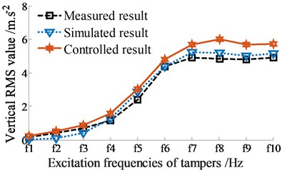
a) Vibration of screed heave
b) Vibration of screed shaking
The controlled results in Figs. 7(a)-(b) indicate that the RMS acceleration response of the vertical screed motion is enhanced, concurrently the RMS acceleration response of the pitching screed angle is significantly decreased under various excitation frequencies of tampers in comparison with the simulated and measured results without control. This major difference is due to the dynamic parameters of angular deviations {, , and } are controlled by the Fuzzy control. Thus, the VSS vibration used Fuzzy control can increase the compression performance and simultaneously improve the paving quality.
4.2. With adding the excitation of vibrator screed
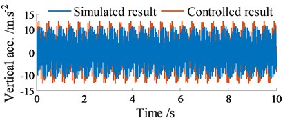
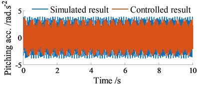
Under the same simulation condition in Section 4.1, an excitation frequency of the vibrator screed 22.5 Hz is then added to the screed. The acceleration results of the vertical and pitching screed motions are plotted in Figs. 8(a)-(b).
Similarly, with the controlled results, the vertical acceleration of the screed is also increased, concurrently the pitching acceleration of the screed is reduced in comparison with the simulated results without control. Besides, the amplitude of the acceleration responses with vibrator screed excitation 22.5 Hz in Figs. 8(a)-(b) is also higher and unstable in comparison with the amplitude of the acceleration responses without vibrator screed excitation 0 Hz in Figs. 6(a)-(b). This issue is due to the influence of the vibrator screed excitation .
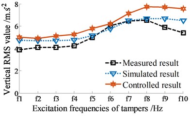
Besides, the RMS acceleration results of the screed are also computed and plotted in Figs. 9(a)-(b). Comparison of all the measured, simulated, and controlled results in both Figs. 7(a)-(b) and 9(a)-(b), it can see that the compression performance is maximum at . When increasing the excitation frequency , the compression performance is significantly reduced under all two cases without or adding of the vibrator screed. This can be due to the effect of the frictional resistance in the VSS. In order to obtain the maximum compression performance, the excitation of the tampers should be used by 14.7 ≤ ≤ 16.8 Hz, particularly at 14.7 Hz. This research result is also close to the existed result in Ref. [4]. However, due to the screed shaking is also maximum at this excitation frequency. Therefore, paving quality is significantly decreased.
Fig. 8Acceleration responses at centre of gravity of screed with excitation of fs2 (fs2= 22.5 Hz)
a) Vibration of screed heave at 10.5 Hz
b) Vibration of screed shaking at 10.5 Hz
Fig. 9RMS acceleration responses at centre of gravity of screed with excitation of fs2 (fs2= 22.5 Hz)
a) Vibration of screed heave
b) Vibration of screed shaking
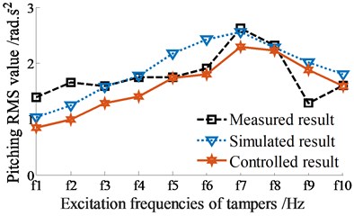
The comparison results between the simulation and measurement in Figs. 9(a)-(b) also show that the curves of the vertical and pitching RMS values at centre of gravity of the screed without control are similar to that of measurement. Meanwhile, the controlled result of the RMS value of the vertical screed motion is also higher than that of the simulated result without control and the RMS value of the pitching screed angle is also lower than that of the simulated and measured results without control. This major difference is also due to the dynamic parameters of angular deviations {, , and } are optimized by the Fuzzy control. Based on the above analysis results, it can be concluded that the compression performance is increased and the paving quality of the VSS is significantly improved under different excitation frequencies of tampers with or without the excitations of the vibrator screed. Consequently, the VSS’s working performance is significantly improved via the dynamic parameters of angular deviations of {, , and } controlled by using the Fuzzy control.
5. Conclusions
1) Based on the measured and simulated results, the vibration excitations of tampers and vibrator screed greatly influence on the VSS’s working performance. The maximum compression performance is obtained at a range of 14.7 ≤ ≤ 16.8 Hz, especially at 14.7 Hz.
2) The compression performance is increased, concurrently the paving quality is significantly improved with the angular deviations of {, , and } controlled by Fuzzy control under various excitation frequencies of the VSS. Thus, the VSS’s working performance is remarkably improved by the control of angular deviations of tampers
3) The result of this study can contribute to the existing body of knowledge of the vibratory screed system of the asphalt paver and provide a reference for the optimal control of other paving machines to further improve the paving performance. Additionally, the result can also be referenced to control the compaction force of soil compactors, which has not yet been considered in existing publications [9, 17], to enhance the soil compactors’ performance.
References
-
Luo D., Feng Z., Wang X. Simulation and experimental study on compacting mechanism of asphalt paver. Journal of Guangxi University, Vol. 35, 2011, p. 729-735.
-
Liu H., Jia J., Ma C., et al. Investigation of paver screed on compaction characteristics of mixture. China Journal of Highway and Transport, Vol. 29, 2016, p. 152-157.
-
Jia J., Wan Y., Liu H. Parameter optimization for a compaction system of vibration screed of an asphalt paver based on a multi-objective genetic algorithm. Journal of Vibration and Shock, Vol. 36, 2017, p. 230-235.
-
Yin C. Dynamic Study and Parameter Optimization about Screed and Tamper Mechanism of the Paver. M.S. thesis, Southeast University, 2018.
-
Wan Y., Jia J. Nonlinear dynamics of asphalt-screed interaction during compaction: Application to improving paving density. Construction and Building Materials, Vol. 202, 2019, p. 363-373.
-
Feng Z., Zhu L., Wang X., Zhao L. Dynamic simulation and parametric selection for tamping mechanism of paving machines. China Journal of Construction Machinery, Vol. 7, 2009, p. 26-30.
-
Xu Q., Chang G., Gallivan V., Horan R. Influences of intelligent compaction uniformity on pavement performances of hot mix asphalt. Construction and Building Materials, Vol. 30, 2012, p. 746-752.
-
Amadore A., Bosurgi G., Pellegrino O. Analysis of hot mix asphalt compaction data by means of fuzzy clustering techniques. Construction and Building Materials, Vol. 40, 2013, p. 430-437.
-
Nguyen V., Zhang J., et al. Vibration analysis and modeling of an off-road vibratory roller equipped with three different cab’s isolation mounts. Shock and Vibration, Vol. 2018, 2018, p. 1-17.
-
Hou H., Wang T., Wu S., et al. Investigation on the pavement performance of asphalt mixture based on predicted dynamic modulus. Construction and Building Materials, Vol. 106, 2016, p. 11-17.
-
Mollenhauer K., Wistuba M. Influence of asphalt compaction procedure on 3d deformation properties. International Journal of Pavement Engineering, Vol. 17, 2013, p. 1-8.
-
Kassem E., Liu W., Scullion T., et al. Development of compaction monitoring system for asphalt pavements. Construction and Building Materials, Vol. 96, 2015, p. 334-345.
-
Kim M., Mohammad L., Phaltane P., et al. Density and SCB measured fracture resistance of temperature segregated asphalt mixtures. International Journal of Pavement Research and Technology, Vol. 10, 2017, p. 112-121.
-
Jia J., Liu H., Wan Y. Dynamic characteristics modelling of the tamper-asphalt mixture interaction: application to predict asphalt mat density. International Journal of Pavement Engineering, Vol. 20, 2017, p. 530-543.
-
Sun J., Xu G., Wang X. Dynamics analysis and improvement of screed based on computer simulation. Journal of Multimedia, Vol. 8, 2013, p. 548-556.
-
Luo D., Feng Z., Wang X. Parameter optimization for compacting system of asphalt paver based on response surface method. Journal of Vibration and Shock, Vol. 31, 2012, p. 92-95.
-
Van L., Jian R. A sensitivity analysis of the importance of the dynamic parameters on the paver’s performance. Journal of Vibroengineering, Vol. 22, 2020, p. 322-326.
-
Nguyen V., Zhang J., Yang X. Low-frequency performance analysis of semi-active cab’s hydraulic mounts of an off-road vibratory roller. Shock and Vibration, Vol. 2019, 2019, p. 1-15.
-
Yildirim S¸. Vibration control of suspension systems using proposed neural network. Journal of Sound and Vibration, Vol. 277, 2004, p. 1059-1069.
-
Ebrahimi N., Gharaveisi A. Optimal fuzzy supervisor controller for an active suspension system. International Journal of Soft Computing and Engineering, Vol. 2, 2012, p. 36-39.
-
Mamdani E., Assilian S. An experiment in linguistic synthesis with a fuzzy logic controller. International Journal of Man-Machine Studies, Vol. 7, 1975, p. 1-13.
About this article

This work has been supported by the Scientific Research Project of Education Department of Hubei Province, China (No. B2019228), Teaching and Research Project of Hubei Polytechnic University, China (No. 2018C45), Open Fund Project of Hubei Key Laboratory of Intelligent Transportation Technology and Device, Hubei Polytechnic University, China (No. 2020XY105), and National Key Research and Development Plan, China (No. 2019YFB2006402).
