Abstract
This paper presents an eddy current damper model that can store electrical energy. The damper is mainly used under strong impact load. On the basis of generating sufficient electromagnetic damping force to resist the impact load, the generated eddy current is guided out of the device through the winding and connected to the energy storage components of the external circuit. In this way, it is realized that the eddy current damper has the function of resisting the impact load. And at the same time, the eddy current damper can convert a part of the impact energy into electric energy and store it in the energy storage element. After research, the theoretical scheme is completely feasible, and the single impact energy conversion efficiency can reach 2.33 %.
Highlights
- This paper proposes a new type of eddy current damper model, which can convert part of the impact energy into electrical energy and store it for strong impact loads.
- The paper analyzes the variation of each physical quantity in the model during exposure to a strong shock load, and the interaction between the physical quantities.
- This paper proposes a scheme for collecting and storing electric eddy currents and verifies the feasibility of the theoretical model.
1. Introduction
The eddy current damper realizes its function based on the principle of electromagnetic induction. It has the advantages of low noise, no direct contact, convenient maintenance, long service life, high reliability and no pollution. Different eddy current dampers are designed with different structures, which can be divided into linear motion eddy current dampers and rotary motion eddy current dampers. Different structures and different relative motion modes have different damping characteristics, but the principle is the same [1, 2]. The eddy current damper will generate an induced current in the conductive body when it is working. Because the conductive body has its own resistance, the induced current generated will be lost to the surrounding environment in the form of heat. From the energy point of view, the eddy current damper is an energy-consuming device.
Many scholars are studying the application of eddy current dampers to vibration reduction systems, hoping to obtain better vibration suppression effects [3, 4]. In the fields of vehicle braking and cushioning shock, eddy current dampers can reduce the impact that it bears in a short period of time through a relatively long motion process. So it has attracted wide attention from scholars [5]. The use of dampers to collect vibration energy has applications in different industries, Many scholars have conducted in-depth research in this area. Many scholars focus their research on how to collect small amplitude vibration energy, and the proposed scheme is suitable for working environments with low power and small displacement [6]. The collected vibration energy is also applied in the suspension system of the vehicle, and the proposed scheme is suitable for the working environment with high power and large displacement. In the process of studying the use of dampers to collect vibration energy by most scholars, the external excitation applied is more a force that lasts for a long time and changes gently. For special working conditions, when subjected to strong impact loads, there is very little research on the dampers to collect impact energy.
Based on the concept of the traditional eddy current damper, this paper proposes a theoretical model of an eddy current damper that can recover impact energy. Focus on the theoretical analysis of the performance of the model when subjected to a single strong impact load. On the basis of good impact resistance, the impact energy is converted into electric energy, and then part of the electric energy is stored in the external energy storage element.
2. Build a theoretical model
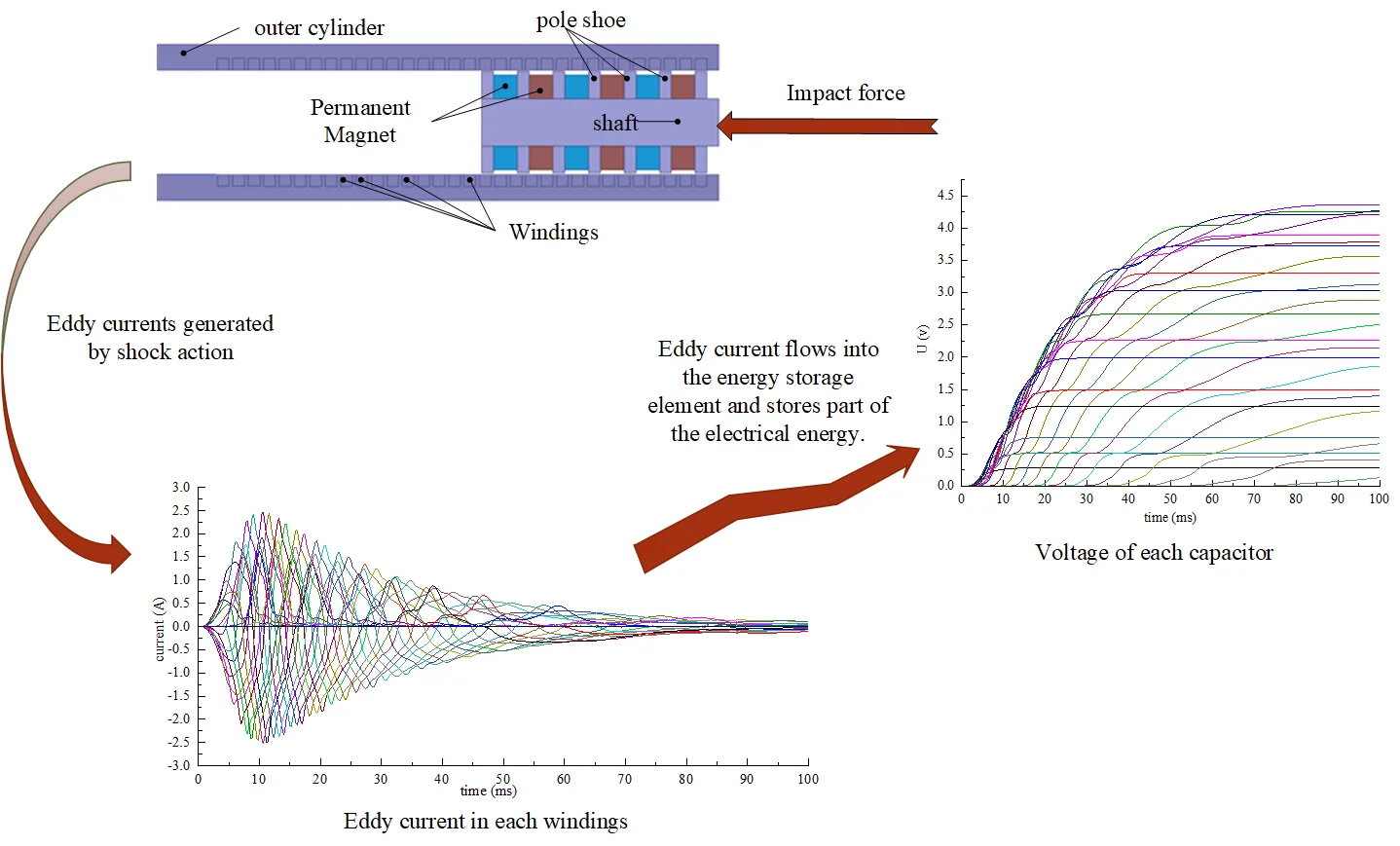
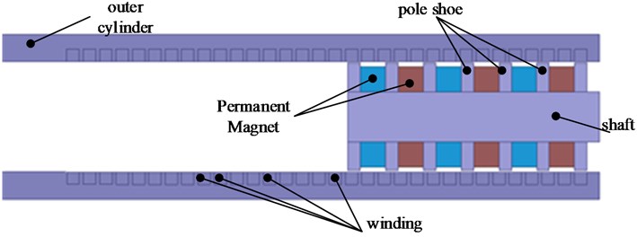
The structure adopted in this paper is a cylindrical eddy current damper, which uses permanent magnets as the magnetic field source, and the hollow outer cylinder surrounds the magnetic field source. The structure after being cut along the axial direction is shown in Fig. 1. A plurality of groups of axially magnetized permanent magnets are fixedly arranged on the shaft. The same magnetic poles of the permanent magnets are arranged oppositely, and they are separated by pole shoes. A plurality of annular slots are opened inside the outer cylinder. Multiple windings are arranged in the slots. The outer cylinder is a stator. The shaft is a moving body. The impact load acts on the shaft, and the shaft carries the permanent magnets to move linearly in the outer cylinder.
Fig. 1Radial structure diagram
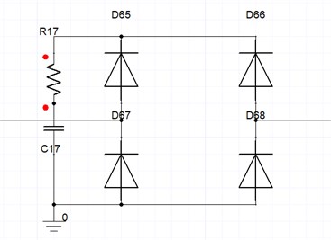
Each winding in Fig. 1 are connected to external energy storage circuits through a wire to form a single-phase loop. The principle diagram of the external energy storage circuit of a single winding is shown in Fig. 2. It consists of a resistor, a capacitor and a bridge rectifier circuit. Capacitors are used to store electrical energy.
Fig. 2Schematic diagram of energy storage circuit
3. Simulation analysis
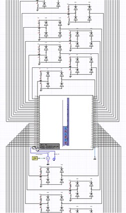
In this paper, the method of Maxwell and Simplorer co-simulation is used. The model in this paper is a cylindrical axially symmetric structure. So drawing the model as a two-dimensional axially symmetric structure in Maxwell can simplifies the calculation process, shortens the calculation time, and does not affect the results. Part as shown in Fig. 3, the Maxwell model is imported into Simplorer software. The external circuit is connected to each winding and the mechanical motion conditions are set. A short-lasting impact force is applied to the moving part of the model. The parameters such as damping force, speed and current in the windings during the movement of the model are calculated. When the calculation starts, the two software perform co-simulation.
Fig. 3Schematic diagram of software co-simulation
According to the electromagnetic induction theorem, a moving conductor generates an induced electromotive force in a magnetic field, and excite an induced current. Electric current is subjected to electromagnetic force in a magnetic field. When the outer cylinder and the permanent magnet move relative to each other, the induced electromotive force generated by the single-turn coil is Eq. (1). And the induced current in the single-turn coil is expressed as Eq. (2). The electromagnetic force generated by the micro-element section in the single-turn coil is Eq. (3). Combined with Eq. (1), (2) and (3), the electromagnetic force on the single-turn coil micro-element section is obtained as Eq. (4):
where is the velocity of the coil, is the magnetic field strength, is the length of the micro-element section of the coil, is the single-turn coil resistance, is the conductivity of the copper wire, is the single-turn coil length, and is The cross-sectional area of a single-turn coil.
Suppose the impact force received by the moving part of the model is . The resultant force of electromagnetic damping force generated by all coils is . The remaining resistance is . The quality of the moving part is , and speed is . According to Newton's second law , get Eq. (5):
From the above formula, when the impact load force is greater than the combined force of the electromagnetic damping force and other resistance, the moving part tends to accelerate continuously. The increasing speed makes the electromagnetic damping force also increase. When the impact load force starts to weaken to be less than the combined force of the electromagnetic damping force and other resistance, the moving part starts to decelerate continuously after reaching a maximum speed. It is foreseeable that the electromagnetic damping force and the speed are both increasing first and then decreasing. According to Eq. (2), it can be found that the current change trend in the coil should also be a process of first increasing and then decreasing.
The results of the curve of impact force, damping force and speed with time are shown in Fig. 4. The damper converts the short-term impact action process into a process that lasts for a long time. The damping force is small, and the speed changes smoothly. The change trend is consistent with the above theoretical analysis. The simulation results can be considered reliable. It can be concluded that the electric eddy current damper designed in this paper has good impact resistance. The disadvantage is that there are some fluctuations in the electromagnetic damping force during the movement. This is due to the interaction between the coil windings arranged at intervals and the unevenly distributed magnetic field. There is room for further improvement of the model.
Fig. 4The graph of impact force, damping force and speed with time
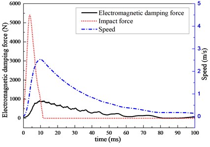
Fig. 5The graph of current in each winding with time
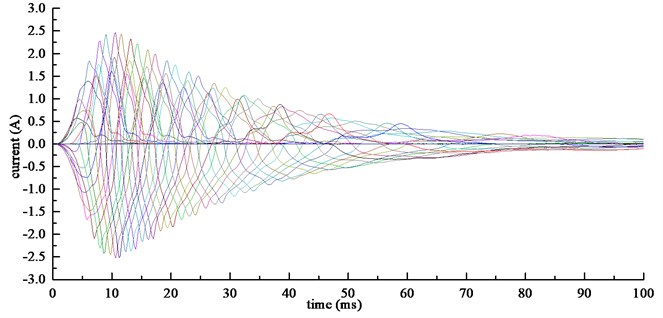
The change curve of the current in each winding with time is shown in Fig. 5. The peak value of the current in different windings is different, and it can be clearly found that the outer envelope of the current curve of each winding shows a trend that increases first and then decreases. Because during the movement, the relative movement speed of the outer cylinder and the permanent magnet first increases and then decreases. The results shown are consistent with the conclusions drawn from the above analysis.
Fig. 6 shows the curve of current change with time. A winding and the corresponding energy storage circuit are selected here. The figure on the left is the change curve of the current in the resistance of the tank circuit with time, and the figure on the right is the change of the current in the winding. The current changes in other windings and tank circuits are similar. Select the capacitors on the two external tank circuits, and their voltage versus time curve is shown in Fig. 7. Fig. 8 shows the curve of each capacitor voltage over time. In the process of resisting the impact force, the voltage of the capacitor continuously rises, and finally stabilizes to realize the storage of electric energy.
Fig. 6The graph of current with time
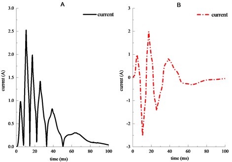
Fig. 7The graph of voltage with time
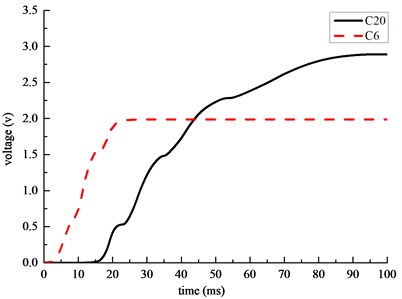
Fig. 8The graph of voltage with time of each capacitor
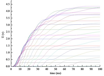
Assuming that the capacitor capacitance is , the capacitor voltage at the initial time is , the capacitor voltage at time is , and the calculation of capacitor energy storage is expressed as Eq. (6):
According to the simulation results, the voltage value of each capacitor can be obtained after the exercise, and the energy stored in each capacitor can be calculated according to Eq. (6). So the sum of the energy stored in all capacitors is 1.033 J. The impact energy can be calculated by integrating the curve of impact force and displacement to be 44.33 J. Therefore, the energy storage efficiency of a single impact is 2.33 %.
4. Conclusions
This paper presents a theoretical model of an eddy current damper that can collect electrical energy. Under the action of impact load, the model has a good impact reduction effect. At the same time, the generated eddy current is introduced into the designed external energy storage circuit for storage. After calculation, the energy storage efficiency of a single impact can be 2.33 %. This paper only presents a preliminary model to analyze the feasibility. Many parameters are not optimal. After further research, more ideal results will be achieved.
References
-
Boldea I., Babescu M. Multilayer theory of d.c. linear brakes with solid-iron secondary. Proceedings of the Institution of Electrical Engineers, Vol. 123, Issue 3, 2010, p. 220-222.
-
Bae J. S., Hwang J. H., Park J. S., et al. Modeling and experiments on eddy current damping caused by a permanent magnet in a conductive tube. Journal of Mechanical Science and Technology, Vol. 23, Issue 11, 2009, p. 3024-3035.
-
Wang Z., Chen Z., Wang J. Feasibility study of a large-scale tuned mass damper with eddy current damping mechanism. Earthquake Engineering and Engineering Vibration, Vol. 3, 2012, p. 391-401.
-
Bae J. S., Kwak M. K., Inman D. J. Vibration suppression of a cantilever beam using eddy current damper. Journal of Sound and Vibration, Vol. 284, Issues 3-5, 2005, p. 805-824.
-
Ren H. E., Donghai H. U., Duanjun Z. Research and development of automobile electromagnetic brake technology for commercial vehicles. Journal of Automotive Safety and Energy, 2013.
-
Triches M., Wang F. A MEMS energy harvesting device for vibration with low acceleration. Procedia Engineering, Vol. 47, 2012, p. 770-773.
-
Jang Seok-Myeong, Lee Sung-Ho, Jeong Sang-Sub Characteristic analysis of eddy-current brake system using the linear Halbach array. IEEE Transactions on Magnetics, Vol. 38, Issue 5, 2002, p. 2994-2996.
-
He Z., Baoquan K., Yinxi J., et al. Characteristic analysis of planar electromagnetic dampers. Proceedings of the CSEE, Vol. 33, Issue 21, 2013, p. 138-144.
-
Saige D., Engelhardt, Jürgen, Katz S. Vibration control of footbridges under pedestrian loading using tuned mass damper systems with eddy current damper technology. IABSE Symposium Report, 2017.
About this article

