Abstract
2 tons 3 meters ship crane as the research object, establish the complete mathematical model of ship crane, and design the time-delay feedback control algorithm to eliminate payload swing on the basis of the built mathematical model. First, a high-precision potentiometer is used to measure the in-plane and out-of-plane oscillation of the payload. Measuring devices for the rotary angle and variation amplitude angle are created, and the anti-swing control hardware system is built by the sensing unit and the High-Speed Data Acquisition hardware system. Secondly, the control software on the VB platform is developed using the time-delay feedback algorithm. Experimentally study the effect of time-delayed feedback controller on payload swing elimination, and use induction method to get the optimal control parameters of the time-delayed feedback control algorithm. At last, the AMEsim-ADAMS co-simulation platform was built to evaluate the payload sway of the ship crane under simulated working conditions. The results show that: the hardware and software systems for anti-swing control built-in the paper can give the real-time and the exact payload swing angles. The method of adding time-delay feedback control signal to the slewing operation signal can achieve better anti-swing effects than the others. At the same time, the delayed feedback control algorithm still has a nice control effect in the case of virtual ship deck motion.
1. Introduction
Anti-sway system of hoisting payload is a system to deal with excessive sway of payload during the crane operation. Its design objective is to control the in-plane and out-of-plane peculation angles of the payload within the safe working range so as to effectively solve the safety problems such as collision accident and payload drop caused by excessive-sway in the process of crane operation [1]. As a kind of rotary hydraulic crane fixed on the deck of a ship, the ship crane can improve the efficiency of port handling, at-sea replenishment, underwater operation equipment launches and recovery [2]. But because of the sea wave and self-reasons, the payload of the ship crane sway greatly, which brings huge challenges to the staffs. Based on this, scholars have done a lot of researches on anti-sway control of the payload, such as Fuzzy Control, Classical PID Control and Neural Network [1-5]. M. Sayed et al. uses a time-delayed active control method to eliminate vibrations of external and parametric excitation amplitude for nonlinear systems subject to 1:4 internal resonance excitation [6]. Ning Sun et al. used the method of changing the crane coordinates to solve the influence of external interference on the crane itself by changing the coordinates of the ship crane, and based on the analysis of Lyapunov proved the boundedness and convergence of the closed-loop signal [7]. Dongkyoung Chwa adopted a sliding-mode control (SMC) method to design a set of control strategies that combined the SMC method with a sliding surface dependent on the position tracking error and a finite-time stabilization method of skew angular rate. The effectiveness of the control strategy is verified on the simulation and experimental platform [8]. Shenghai Wang et al. established a combined ship motion compensation (CSMC) method based on the direct ship motion compensation proposed by the Barge Master, and proposed the dynamic model of DSMC and CSMC in a unified way. Through numerical simulation, it is found that the power consumption of CSMC at sea is much smaller than that of DSMC [9]. Lon-Chen Hung [10] proposed a self-tuning fuzzy sliding mode control method. This method, which used heuristic fuzzy reasoning and omitted the process of finding the appropriate sliding mode coefficients, can significantly improve the response speed of the system. Yuzhe Qian et al. adopted a repetitive adaptive learning control strategy, which introduced the period identifier into the control strategy, and designed an effective offshore crane nonlinear controller [11]. Hans Butler combines the parameters of modelling mechanics with the structural knowledge of the payload itself, applies the adaptive method to the anti-sway system of the payload and verifies the feasibility of the method [12]. G. A. Manson takes the running time of the traction trolley of the bridge crane as the objective function and indirectly controls the payload’s sway by optimizing the objective function [13]. Y. Sakawa defines fastest transfer time and minimum swing of the load during the transfer as optimal target. For a new computational technique, the computed optimal control schemes are obtained and applied to the motor’s torques. Numerical results show good control effects on swing a load. [14]. Parker reduces the sway of payload during the operation of ship crane by using the input shaping method, but the system still has a large time delayed [15]. Golafshani and Aplevich directly apply the linear calculation model to the rotary crane, which can play a certain restraining role, but the effect is not obvious due to the complexity of the payload sway itself [16]. M. A. Ahmad et al. builds a 2-DOF rotary crane model, and Proportional-Derivative (PD) controller and Proportional-Derivative (PD)-type Fuzzy Logic controller is used in their investigation [17]. Kunihiko, Nakazono et al., designed a three-layer neural network controller (NC) based on genetic algorithm (GA) to control the lifting of the crane hoist. This algorithm not only greatly simplifies the design of the controller. The effect is better than the traditional feedback control [18]. William Sing hose et al. [19] takes the dynamic model of a gantry crane as the research object, and proposed an input shaping method to reduce the residual vibration of the load. Naoki Uchiyama, Huimin Ouyang, etc., through the dynamic model of the rotating crane, an open control method that eliminates residual oscillations only by boom motion [20]. Jaroslaw Smoczek proposed a fuzzy feedback anti-swing control system based on fuzzy logic. The discrete time control method was used to verify the payload swing suppression effect in the bridge crane [21]. Tai-Yen, Thomas Kuo, etc. carried out simulation and experimental research to achieve fast crane operation while minimizing swing angle [22]. M. J. Maghsoudi and Z. Mohamed conducted research on optimal performance control strategies for 3D crane models [23]. During the operation of the ship crane, the payload swing shows a strong non-linearity. For nonlinear control, the main research methods currently studied by scholars are: M. Sayed et al. applied active control to a nonlinear dynamic beam system to eliminate its vibration [24]. Kandil A. et al. studies the oscillations of a 16-pole rotor active magnetic bearing system by means of a conventional proportional derivative controller [25]. M. Sayed et al. uses the multiscale regression (MSP) method to study the vibrational and numerical solutions of a system simulating nonlinear combined beam vibrations [26]. Y. S. Hamed et al. Multiscale uptake and numerical solutions for vibration analysis and control of a system simulating nonlinear combined beam vibrations are investigated [27]. Scholars at home and abroad have made a lot of explorations on the control methods and sway strategies of ship cranes, and bring forward various innovative strategies. However, when verifying the effect of the test, most of the verification is carried out by building a simple model, and there are few cases of testing on a real ship crane. Even if someone had done experiments on a ship crane, no one had done experiments on a slewing ship crane.
Based on the above background, a complete mathematical model of crane payload swing is established with a 2-ton 3-meter marine crane as the research object. According to this mathematical model, the time-delayed feedback of the ship crane payload swing elimination control is designed.
2. Anti-sway control algorithms for payload
2.1. Mathematical model
As shown in Fig. 1, this is a real object of a rotate ship crane with a payload of 2 tons and a rope length of 3 meters. In Fig. 1 among them, is the central position of the crane; is the length of the crane wire rope, and is changed during the hoisting operation; is distance from the center of rotation to the hinge of the boom and the turntable, is the length of the lifting arm, is the mass of lifting weight; and are in-plane and out-of-plane pendulation of the payload; and are slewing angle and luffing angle. According to the inertia of coordinate shown in Fig. 1, the position of the vertex of the boom can be obtained:
Fig. 1Mathematical model of the crane
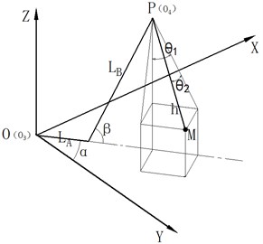
The position of the payload in the inertial coordinate system is as follows:
The size or value of , , , in the equation will change with time. According to the relationship between kinetic energy and potential energy, the following results can be obtained:
and is the lifting weight mass of the crane in operation.
From Eq. (3) and (4), we can get that the Lagrange operator of the payload is:
Tracking the deviation of the payload with the vertex of the boom when lifting heavy load, the in-plane and out-of-plane pendulation of , are calculated. Then, the Lagrange’s equation is obtained:
where, , refers to the influence of external forces on the lifting load, including sea wind and waves.
When the swing angle of the payload is less than 10°, it can be considered that:
According to the above Equations, the mathematical model of the sway system of the payload can be obtained as follows:
Substituting Eq. (1) into (8) and (9):
From the Eqs. (10) and (11), the following conclusions can be drawn: 1) The in-plane angle and out-of-plane the pendulation equations of the Ship’s Crane payload have undamped forced vibration, once the swing and the variable amplitude operation are stopped, the sway of the payload is undamped free vibration; 2) the payload There is a coupling between the in-plane angle and out-of-plane the pendulation movements of the payload, and the motion is reversed. 3) when stop the operation the payload of the swing frequency is the same in the in-plane and out-of-plane, and swaying frequency is , Only related to rope length, but when operation process the swaying frequency is related to rope length, swing speed, speed of amplitude and amplitude of acceleration and amplitude angle, simultaneously less than the swing frequency when not working.
2.2. Design of time-delayed feedback controller
In reference [28], it is found that adding delayed feedback to the dynamic system is equivalent to adding damping to the system, which can make the system stable. The principle of time-delayed feedback is shown in Fig. 2 [29].
Fig. 2Time delayed feedback control schematic diagram
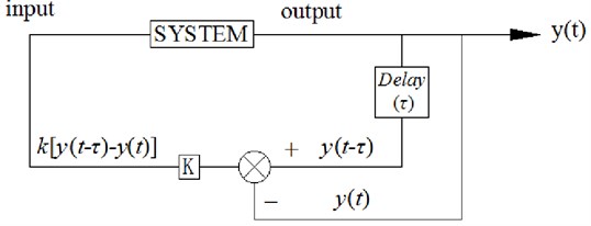
In Fig. 2, is the output of the control system, and , are delayed time and gain respectively. The principle is that the output signal of the system is delayed and not delayed, then the difference is made; the difference is multiplied by a gain , and the result is re-input to the input end of the system. The time-delayed feedback controller is adopted in this paper. Delayed feedback control is adopted to achieve the effect of rapid attenuation of the payload. That is to say, the vertex of the boom of the crane can track the position of the payload. The difference between the delayed payload’s position and the non-delayed one are added to the input signal of the proportional valve in the hydraulic system of the ship crane. Finally, the vertex of the boom and the end of the payload are in a plane, which thus eliminates the sway of the payload.
After the time-delayed feedback control is added to the Eqs. (10) and (11), the sway equation of the payload is as follows:
Eqs. (15) and (16) are further simplified:
Eqs. (14) and (15) are the same in form, so only Eq. (14) is analyzed.
According to the sway form of the payload, it is solved by the trial function method in the methods of solving the non-linear equation, and assume that the solution of the Eq. (14) is as follows [30]:
According to the damping system, the system sways undamped when is zero; When is greater than zero, the payload sway becomes larger and larger, and the system cannot converge; When is less than zero, the sway of the payload decreases. When 0, and the values of k and can be obtained when the system is in a critical state. According to the critical values of k and τ, the ranges of and are determined when the value is less than zero. Bring Eq. (16) into Eq. (14), Then, the coefficients before and are set to 0. The following equations can be obtained:
For given values of and , as well as the slewing speed of the crane the movement frequency of crane payload control system is calculated. The amplitude and initial phase angle can be determined according to the initial condition. In this way, the solution of the equation of the in-plane angle in time domain can be obtained. Let , Eq. (17) and Eq. (18) can be expressed is:
It is known that the sway length of the existing small rotary ship crane in the laboratory is 2.3 m. It is concluded that the sway period of the payload is:
The delayed time of time delayed feedback system should be between 0-.
Eq. (19) and (20) show that when 0:
When : and –1, from the calculation of we can get that:
and 1, from the calculation of we can get that:
The 0 calculated by Eq. (24) does not meet the requirements of the system.
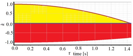
Based on the above solution, the stable boundary of the payload anti-sway control system is determined. The stable area of the system in the yellow zone with is shown in Fig. 3.
Fig. 3Stable area of the control system
3. Experimental preparation
3.1. Payload swing angle measuring device
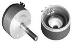
In order to verify the established mathematical model can be applied to the Ship’s Crane payload control research. For the measurement of the swaying angle, based on high precision potentiometer, building the payload swing angle measurement scheme. The swing angle measuring system is simple in structure, easy to install, and most importantly. The real-time measurement can be realized. The laboratory payload swing angle measuring device is shown in Fig. 4.
Fig. 4Payload swing angle measuring device
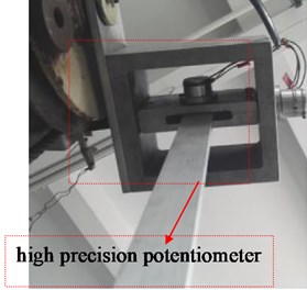
Use WDD35-D1 precision conductive plastic potentiometer as potentiometer on an angle sensing device, the working principle is to add a stable voltage value across the sensor resistance. The movement of the brush on the elastic resistance of the guide rail will change the change of the measured resistance, such outputting the voltage value corresponding to the swing angle. The displacement of the brush is consistent with the measured displacement, and the output voltage value is linear with the displacement. According to the linear relationship between the output voltage and the angle of rotation of the central axis of the potentiometer calculated sway angle of the payload. The shape and working principle of the potentiometer is shown in Fig. 5.
Fig. 5Shape and working principle of the potentiometer
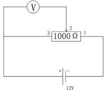
In the experiment the potentiometer resistance is 1000 Ω, measurement accuracy is ±0.25 Ω, rotation stroke is 345°, the resistance value changes linearly, and the external voltage is 12 V. When the swing angle changes by 1°, the corresponding resistance change is:
Can be obtained:
In the Equation, according to the measured voltage difference between the swing state of the payload and the initial equilibrium state, the relationship between the swing angle and the voltage difference can be obtained as follows:
3.2. Variable amplitude angle measuring device
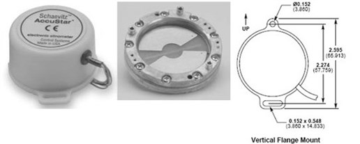
The AccuStar-I series of single-axis analogy output tilt sensors are used to measure the amplitude of the crane during luffing, as shown in Fig. 6.
Fig. 6Angle sensor outline structure and dimension drawing
3.3. The rotary angle measuring device
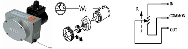
The CKS256 high-precision rope-type displacement sensor is selected as the measurement of the swing angle of the crane. The rope-type displacement sensor can be directly applied to the measurement of the linear guide motion system. The rope displacement sensor is the perfect combination of an angle sensor and a linear displacement sensor. It has the advantages of small installation size, compact structure, large measuring stroke, and high precision. The structure and measurement principle is shown in Fig. 7.
Fig. 7Pull rope displacement sensor structure and measurement principle
3.4. Mathematical model validation
The maximum rotation speed of the actual crane slewing mechanism is 0.8 rev/min. The voltage input signal of the proportional and rotary proportional valves is ±10 V. In order to make the experimental results compared with the simulation results, the input signal of the rotary proportional valve in the simulation model set in MATLAB is also ±10 V and maximum rotational speed of the sway and variable amplitude mechanism is also 0.8 revs/min. Finally, the comparison between the experimental and simulated swing angles can be obtained. The simulation results are significantly consistent with the experimental values in Fig. 8. It can consider that the model can correctly represent the actual system. The difference should be caused by partial linearization during the establishment of the mathematical model.
Fig. 8Comparison of the pendulation of the payload's experiment and simulation
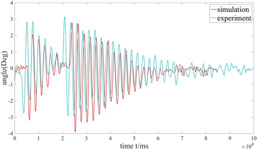
a) Out-of-plane angle
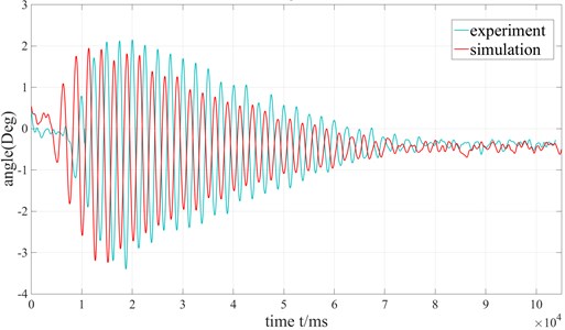
b) In-plane angle
4. Anti-sway control of ship crane
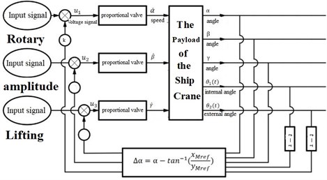
The principle of anti-sway control of payload is shown in Fig. 9, , and are the input signals of the electromagnetic proportional valves; is the delayed time; and are in-plane and out-of-plane pendulation of crane payload respectively; and are the desired positions of the vertex of the boom after adding delayed. By adding the time delayed to in-plane and out-of-plane pendulation of the payload of the ship crane, the anti-sway control of the payload is realized. According to Eqs. (17) and (18), the position of the payload with time delayed control is calculated, and then the desired angle of the payload is calculated. Then the slewing angle difference is obtained, which is added to the input signals of the proportional valves.
Fig. 9Anti-sway control principle for the payload of the ship crane
4.1. Experimental delay feedback control
The purpose of this section is to determine the values of the delay time and the feedback gain coefficient for the best oscillation control effect in delayed feedback control. First, try to use different delay time at 0.1. As showed in Fig. 3, values of and are in the yellow area when the system is stable. Thus, the range of delay time is between 0-1450 ms and the value of is between 0-1.
4.1.1. Crane swing operation
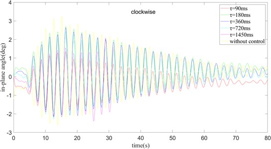
First, the ship crane is rotated in a clockwise direction. 0.10, values are taken as 90 ms, 180 ms, 360 ms, 720 ms, 1450 ms and without delay control, the oscillation curves of the in-plane angle and out-of-plane angle are shown in Fig. 10.
Fig. 10k= 0.1 and turning clockwise, the out-of-plane angle curve of payload rotation operation
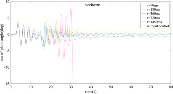
Fig. 10 shows that the maximum swing amplitude of the payload without delay control. 0 is located on the boundary of the stable region shown in Fig. 8, which indicates that although 0, 0 1 can be stabilized on the boundary, the swing amplitude is larger and the time required to reach the stable state is longer. Correspondingly, when 1450 ms, it can be clearly seen that the oscillation amplitude of the payload is getting larger and larger and cannot be converge. This indicates that 1450 ms, 0.10, the point is outside the boundary of the stable region and the system is unstable leading to divergence. When 90 ms, the oscillation amplitude of the payload first increases and then decreases. In the case of 180 ms, the swing amplitude of the out-of-plane angle of the payload is larger than when 90 ms, but the stabilization time is a little longer. In the case of 360 ms, the swing amplitude of the out-of-plane angle of the payload surface is comparable to that when 180 ms, but the speed of stabilization is faster, and the required stabilization time is shorter than when 90 ms. When 720 ms, the swing amplitude of the out-of-plane angle is slightly smaller than when 360 ms, but the time needed for stabilization is almost the same as when 360 ms.
1450 ms, the swing amplitude of the outside angle of the payload will diverge, and a stable solution cannot be obtained. In the case of 90 ms, the swing amplitude of the external angle is less than in other cases, but the final stable position has a larger error compared with the target position. In the experiment of 180 ms – 720 ms, the convergence speed gradually becomes faster as increases, but the maximum swing amplitude of the out-of-plane angle does not change much. When 180 ms and 360 ms, the error between the out-of-plane angle of the surface and the target position is smaller after the outside angle reaches a stable state.
From Fig. 11 shows that when 0 ms, the swing amplitude of the in-plane angle of the payload is the largest, and finally it gradually decays to a stable value. When 1450 ms, the waveform is different from the previous one, showing a trend of divergence gradually. When 90 ms, the swing amplitude of the in-plane angle is much lower than in the case of 0 ms, and the time to stabilize is also shorter. When 180 ms, the amplitude of the in-plane angle swing is much larger than 90 ms, and the stabilization time is slightly longer than 90 ms. When 360 ms and 720 ms, the swing amplitude of the in-plane angle is comparable that when 180 ms, and the time required for stabilization is basically the same as when 360 ms. When 360 ms and 720 ms, the deviation from the target angle is small after reaching a steady state. By synthesizing the images of the in-plane angle and the out-of-plane angle, it is concluded that when 360 ms, the result is better with the control. From the above, we find: 1) The time delay algorithm can reduce the swing amplitude of the payload, and at the same time can reduce the time required for the payload to stabilize. 2) The time delay control strategy has similar effects on the inner and outer angles of the payload surface, that is, when 90 ms, the amplitudes of the two swing angles are both small, but they will have a certain angle with the set angle after reaching stability. Deviate. When 180 ms and 360 ms, the control effect of the outside angle of the plane is better, and the control of the inside angle of the plane is also better.
Fig. 11k= 0.1 and turning clockwise, the in-plane angle curve of payload rotation operation
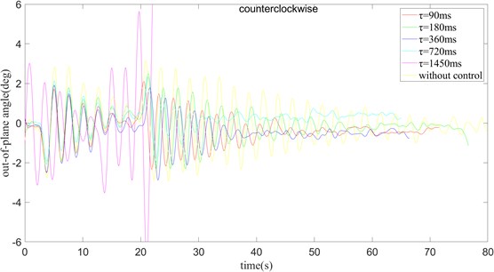
The following two figures change the clockwise rotation to counterclockwise rotation under the condition of 0.10. By observing the Figs. 12 and 13, analyze the influence of the time delay algorithm on the swinging process of the payload.
Fig. 12k= 0.1 and turning counter clockwise, the out-of-plane angle curve of payload rotation operation
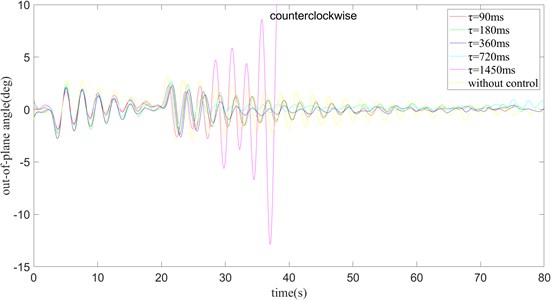
Similar to the clockwise situation, when 0, in other words, when there is no swing, the swing amplitude of the payload is the largest. When 1450 ms, the swing amplitude gradually becomes larger and cannot be stabilized near a value. When 90, the swing amplitude of the payload first increases and then decreases, and it takes about 60 ms to stabilize. When 180 ms, the swing amplitude of the outside angle of the payload is larger than when 90 ms, and the stabilization time is longer. The case of 360 ms and 720 ms is the same as the case of 180 ms, and the time to stabilize is basically the same as the maximum amplitude of the out-of-plane angle swing. Only when 360 ms, the angle error is the smallest.
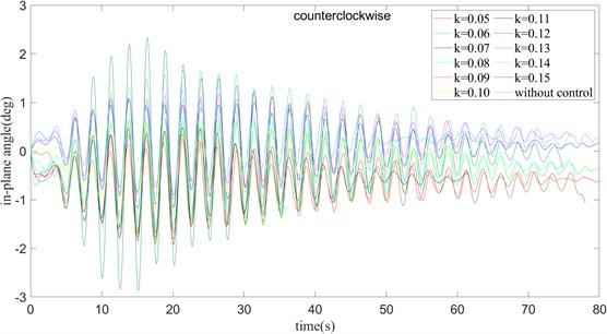
In summary, when changes from 0 to 720 ms, the amplitude of the in-plane angle swing gradually reduces, and the time required to reach stability gradually decreases. When 180 ms, 360 ms, and 720 ms, the maximum swing amplitude of the in-plane angle is basically the same. The maximum swing amplitude of the in-plane angle is the smallest when 90 ms.
Fig. 13k= 0.1 and turning counter clockwise, the in-plane angle curve of payload rotation operation
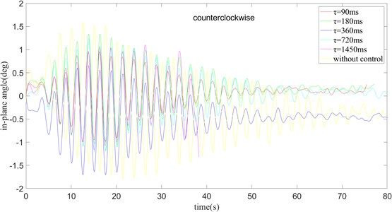
When 90 ms, the swing amplitude of the in-plane angle is small, while compared to the case where the time delay is not added, the swing amplitude is still much smaller. When gradually increases from 180 ms to 720 ms, the maximum swing amplitude of the in-plane angle of the payload does not change a lot, but the time required to reach a stable state gradually decreases. When 1450 ms, the swing amplitude increases with time, and the payload cannot be stabilized. Through the above analysis, when rotating counterclockwise, the optimum effect is obtained when 0.10 and 360 ms.
Compares the effect of the swing angle of the payload with different values of the parameter when rotating clockwise and 360 ms.
Fig. 14τ= 360 ms and turning clockwise, the out-of-plane angle curve of payload rotation operation
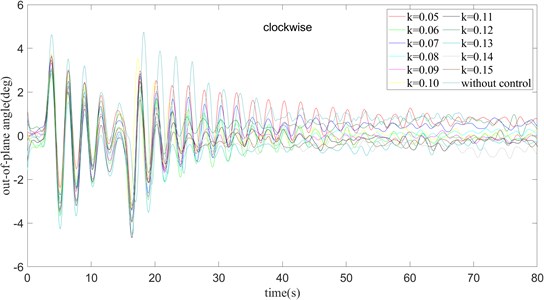
In the Fig. 14 when 0.05, the swing amplitude of the out-of-plane angle decreases with the increase of time, and it has reached a stable state at about 65 ms. When 0.06, the maximum angle of the swing amplitude is basically the same as 0.05, but the stable speed is shorter than when 0.05. Through continuous comparison, it shows that with the continuous increase of the value of k, the time required for the outside angle of the plane to reach a stable state continues to decrease, but the maximum swing amplitude of the outside angle of the plane is basically unchanged.
In brief, when 0.08, it is just stable near the outside angle of 0, which means that it is just near the required angle when it is finally stable. Although 0.05, 0.12, and 0.07 have a good stabilization effect, there is always an error of about +0.6 degrees away from the target angle. These basic groups of 0.10, 0.06, 0.08, and 0.09 It is stable near the target angle, but in the case of 0.10, the magnitude of change after stability is still large. In the case of 0.09, the target value is above its stable range, which means there is still some error from the target angle. In the case of 0.06 and 0.08, these two sets of data are very stable around the target angle, and the amplitude of change is not large, but considering that 0.08, it takes less time to stabilize, 360 ms, should be set to a value of 0.08, and the anti-swing effect is the best.
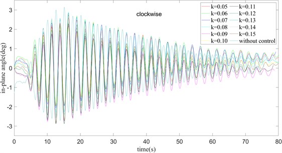
Fig. 15τ= 360 ms and turning clockwise, the in-plane angle curve of payload rotation operation
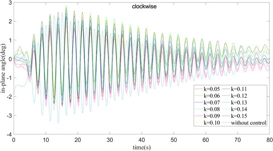
From the Fig. 15 with the analysis, we realize that the in-plane angle and the out-of-plane angle also have the constant increase of , the faster the payload tends to stabilize at the in-plane angle. Not only that, when gradually increases, the maximum swing amplitude of the in-plane angle remains basically unchanged. From the above figure, it can be concluded that when 0.06, 0.10, 0.13, and 0.15, the in-plane angle is finally stable above the target position. When 0.05, 0.09, 0.11, 0.12, 0.14, the in-plane angle is finally stabilized below the target position. Only when 0.07 and 0.08, the in-plane angle is stable near the target angle. Considering that gradually increases, the steady speed gradually becomes faster, taking 0.08 is a better parameter selection scheme among the current sets of data.
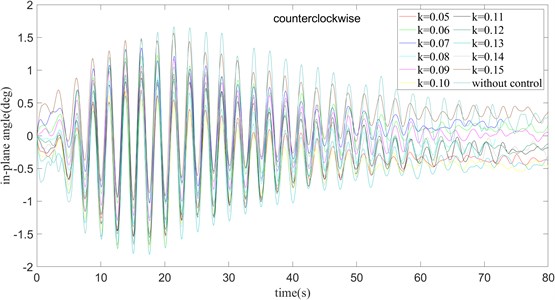
From the Fig. 16, 17, we can find that the changing trend of the system is similar to that of the clockwise rotation. In the case of 360 ms, as the value of gradually increases, the time required to stabilize the outside angle of the surface gradually decreases, but the maximum swing range of the out-of-plane angle of the surface does not change a lot. The change of the in-plane angle is also similar to that in the clockwise case. With the gradual increase of , the variation of the swing amplitude of the in-plane angle is not obvious. The convergence speed is basically the same in the rest of the experiments, except for 0.05. It reaches a steady state around 65 ms. By observing the position of the steady state in Fig. 16, it can be found that when 0.07 and 0.12. The out-of-plane angle is basically stable at the target angle. Considering the swing situation of the in-plane angle comprehensively, it can be found that when 0.07, the delay feedback strategy has the best control effect. In the case of only rotation, the addition of the delay feedback strategy greatly reduces the time required for the out-of-plane angle to reach a stable state, and reduces the swing amplitude of the inside and outside angles. Therefore, it is not required to select a set of appropriate values of and to obtain better control results.
Fig. 16τ= 360 ms and turning counter clockwise, the out-of-plane angle curve of payload rotation operation
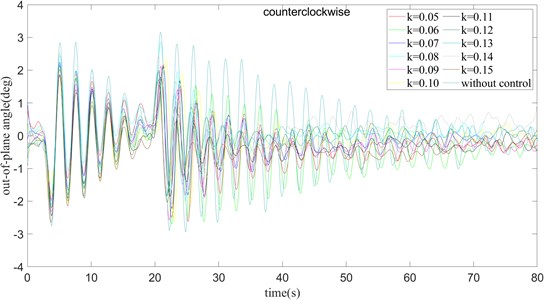
Fig. 17τ= 360 ms and turning counter clockwise, the in-plane angle curve of payload rotation operation
4.1.2. Cranes operate at 10 degrees of amplitude change
The following eight figures show the control effect of the time delay algorithm when the two operations, rotation and pitch, are performed at the same time. In the beginning, change the value of τ under the condition of 0.10, observing the influence of the change of on the effect of the time delay feedback algorithm.
From Figs. 18 and 19, it can be seen that the time required for the out-of-plane angle to reach the steady state and the maximum magnitude of the outer angle oscillation gradually decrease for 90, 180 ms, 360 ms and 720 ms. Therefore, it can be concluded that when is constant, the time required for the system to reach the steady state and the maximum swing range gradually become smaller as increases. When 90 ms and 180 ms, the range of change of the in-plane angle of the payload surface and the time required for stabilization are relatively small, but when 360 ms and 720 ms, the time required may be longer. By comparing the positions when the system is kept stable, it can be found that when 720 ms, the swing amplitude and convergence time are relatively small and a better control effect is achieved.
From Figs. 20 and 21, it can be seen that the crane is operated in counterclockwise direction, the time required for the out-of-plane angle to reach the steady state gradually decreases in the cases of 90, 180 ms, 360 ms, 720 ms. In the case of 1450 ms, the steady state cannot be reached. However, the maximum swing amplitude of the out-of-plane angle is small except when 90 ms, and there is basically no change when 180 ms, 360 ms, and 720 ms.
Fig. 18k= 0.1 and turning clockwise, the out-of-plane angle curve of payload rotation and amplitude operation

Fig. 19k= 0.1 and turning clockwise, the in-plane angle curve of payload rotation and amplitude operation
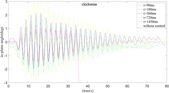
Fig. 20k= 0.1 and turning counter clockwise, the out-of-plane angle curve of payload rotation and amplitude operation
In the case of counterclockwise (Figs. 20 and 21), the change of the internal angle is not obvious. In addition to 1450 ms, the internal angle of the plane cannot be stabilized, the stabilization time and the amplitude of the change when takes other values are very similar. With comparison, it looks that in the case of counterclockwise rotation and 0.10, is taken as 180 ms, which can minimize the deviation of the system from the target state in the steady state, so it is the best combination among the five combinations. Similar to the case of only turning, the purpose of the following two sets of experiments is to select a more appropriate value of . In the case of 360 ms, the influence of the value of and the direction of rotation on the swing angle of the payload is considered.
Fig. 21k= 0.1 and turning counter clockwise, the in-plane angle curve of payload rotation and amplitude operation
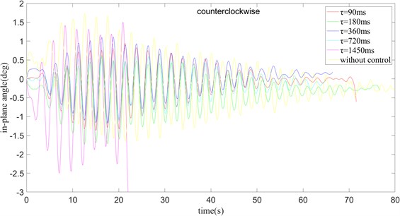
Fig. 22τ= 360 ms and turning clockwise, the out-of-plane angle curve of payload rotation and amplitude operation
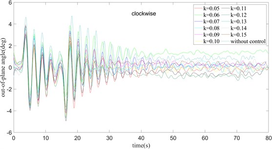
Fig. 23τ= 360 ms and turning clockwise, the out-of-plane angle curve of payload rotation and amplitude operation
It can be seen from Fig. 22 and Fig. 23 that in the clockwise case, with the increase of , the time required for the outside angle of the payload to stabilize gradually decreases. However, there is no change in the amplitude of the outside angle of the surface, which is consistent with the conclusion obtained in the case of only the rotation operation. The swing of the in-plane angle is less affected by the value of , and basically reaches a stable state around 65 ms. At the same time, integrating the outside angle of the surface and the inside angle of the surface after reaching a stable position, it can be concluded that when rotating clockwise and 0.08, 360 ms, the error between the actual angle and the target angle is the smallest, and the anti-swing effect is the best.
Fig. 24 and Fig. 25 show us that, as increase, the time required for the outside angle of the plane to reach a stable state gradually decreases, just as that in clockwise. Except when 0.13, the maximum variation amplitude of the outside angle of the surface suddenly increases, and the swing amplitude of the outside angle of the surface is basically unchanged in other cases. For the in-plane angle, except for the case of 0.13, the swing amplitude of the in-plane angle becomes larger. In other cases, the maximum swing angle of the in-plane angle and the stable time are almost the same. Considering the steady-state error between the actual angle and the target angle after stabilization, the combination of counterclockwise rotation, 0.07, 360 ms is better.
Fig. 24τ= 360 ms and turning counter clockwise, the out-of-plane angle curve of payload rotation and amplitude operation
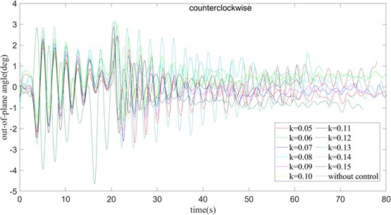
Fig. 25τ= 360 ms and turning counter clockwise, the in-plane angle curve of payload rotation and amplitude operation
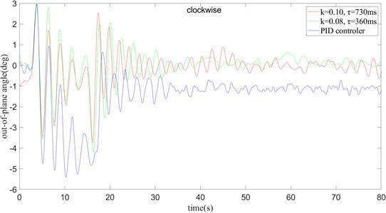
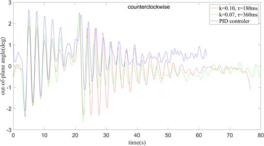
In the condition with only rotation, it can be seen that when 0.07, 360 ms, 0.08, 360 ms, the swing amplitude of the payload at both the outside angle and the inside angle Smaller, it can be seen that a better control effect has been achieved. At the same time, it is compared with the PID control algorithm commonly used in the industry. From the curve in the figure, it can be seen that the time delay feedback control method is better than the traditional PID control method in the control of the outside angle and the inside angle of the surface, and when 0.08, 360 ms and clockwise mode, the best control effect is achieved.
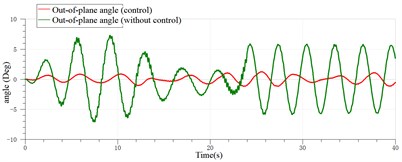
In the condition with only rotation, the better combination of clockwise and counterclockwise cases is compared, and the most suitable parameter setting is obtained in the case of only rotation. And compared with the effect of the PID algorithm commonly used in actual production. Fig. 26 can be used for the slewing operation of the crane, and the two anti-swing methods have more obvious suppression effects on the payload swing. However, in Fig. 26(a), it can be seen that the PID algorithm swings more widely after it reaches stability. In Fig. 26(b), it is found that there is a large deviation from the target angle after reaching the stability. On the contrary, the time-delay feedback methods have achieved better results in anti-swing. And under clockwise operation, the optimum is achieved when 0.08 and 360 ms. And under counter clockwise operation, the optimum is achieved when 0.07 and 360 ms.
Fig. 26PID control and time delay feedback control under the rotation operation are used to compare the anti-swing effect
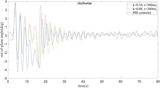
a) The clockwise
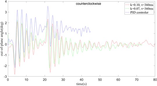
b) The counter clockwise
When crane slewing and amplitude change 10 degrees operation, from Fig. 27 can be found that in the more complex operating mode, the time delay algorithm and the PID algorithm can better suppress the swing of the payload, but the PID algorithm in the control accuracy is slightly worse than the time delay algorithm. By comparison, it can be concluded that in the case of oscillation, the system can be best controlled by using the values of and for counterclockwise and clockwise rotation of 0.08, 360 ms and 0.07, 360 ms, respectively.
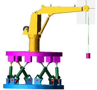
4.2. Simulation study of ship deck motion based on time delay
When the ship is sailing on the sea, the payload will oscillate from the deck. Therefore, the six-degree-of-freedom ship deck motion simulator is used to simulate deck motion, as shown in Fig. 28. and the designed delay feedback controller simulates the system’s sway through the AMEsim-ADAMS co-simulation platform, here the crane only does the rotary operation. According to the conditions of China Classification Society for offshore cranes working at sea, the roll cannot be greater than 5(Deg) and the pitch cannot be greater than 2(Deg). The situation we simulated is the worst permitted scope of work, and also the most representative.
Fig. 27PID control and time delay feedback control under the rotation and amplitude operation are used to compare the anti-swing effect
a) Clockwise
b) Counter clockwise
Fig. 28Wave simulation platform
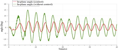
The sway control of the payload of the ship crane with the rolling of 5(Deg) is shown in Fig. 29.
The sway control of the payload of the ship crane is shown in Fig. 30 when the heave amplitude is 0.01 m.
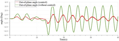
The sway control of the payload of the ship crane with the pitching of 2(Deg) is shown in Fig. 31.
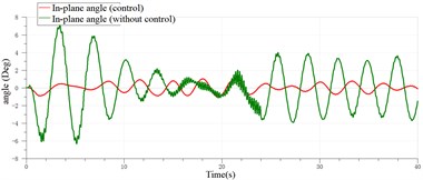
According to Figs. 29-31, it can be found that the sway of the payload of the ship crane is attenuated to a certain extent with the controller. However, because the payload system itself is highly nonlinear, and in order to simplify the model, the payload is regarded as a particle in the model. The time delayed feedback controller was designed and applied to the platform of ADAMS and AMESim co-simulation of the ship crane, which verified the effectiveness of the designed time delayed feedback controller in restraining the sway of the payload.
Fig. 29Sway control effect of the payload with the rolling of 5 (Deg)
a) In-plane angle
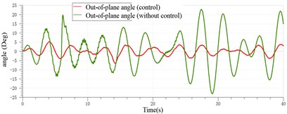
b) Out-of-plane angle
Fig. 30Sway control effect of the payload with the heave of 0.01 m
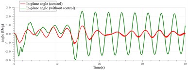
a) Out-of-plane angle
b) In-plane angle
Fig. 31Sway control effect of the payload with the pitching of 2(Deg)
a) Out-of-plane angle
b) In-plane angle
5. Conclusions
In this paper, a ship crane of 2-ton and 3-meter is the research object, and the effect of the swinging payload of the ship crane after the time delay feedback control method is studied under the simultaneous action of the slewing operation and the 10° luffing operation. We can conclude the following:
1) The physical model of the crane is obtained through the simplification of the ship crane, and the mathematical model of the ship crane is obtained through theoretical deduction. The correctness of the mathematical model built is verified by simulation experiments.
2) Through the derivation of the time delay feedback algorithm, the value range of the parameters and in the time delay feedback of the ship crane is obtained, is between 0 and 1, and is between 0 and 1450 ms. In the feasible region and combined with the previous actual control experience, 8 different sets of , and rotation methods are selected for experiments. It is found through experiments that the time delay control strategy can effectively restrain the swing of the payload. Compared with the commonly used PID control strategy, the time delay control method has better control effect. The comparison method yields better time delay feedback for counterclockwise operation mode with 0.08 and 360 ms.
3) AMEsim-ADAMS co-simulation platform was built to simulate the ship crane payload system under simulated deck motion conditions. According to the optimal controller parameters 0.08, 360 ms obtained in Section 4.1, the sway elimination effect of time-simple delayed feedback is simulated numerically under the deck motion condition. From the results obtained from the simulation, we can find that the swing angle of the payload still decreases significantly under the influence of the simulated waves, indicating the correctness of the controller itself and the parameter settings.
References
-
Cho Sung-Kun, Lee Ho-Hoon A fuzzy-logic anti swing controller for three-dimensional overhead cranes. ISA Transactions, Vol. 41, Issue 2, 2002, p. 235-243.
-
Mahfouf M., Kee C. H., Abbod M. F., Linkens D. A. Fuzzy logic-based anti-sway control design for overhead cranes. Neural Computing and Applications, Vol. 22, Issue 9, 2000, p. 38-43.
-
Benhidjeb A., Gissinger G. L. Fuzzy control of an overhead crane performance comparison with classic control. Control Engineering Practice, Vol. 3, Issue 12, 1995, p. 1687-1696.
-
Hanafy M. Onla Control of Gantry and Tower Canes. Virginia Polytechnic Institute and State University, Blacksburg, Virginia, 2003.
-
Choi Kim S. U. J. H., Lee J. W. A study on gantry crane control using neural. Network Two Degree of PID Controller, Vol. 15, Issue 22, 2001, p. 755-761.
-
Sayed M., Mousa A. A., Alzaharani D. Y. Non-linear time delay saturation controller for reduction of a non-linear vibrating system via 1:4 internal resonance. Journal of Vibroengineering, Vol. 18, Issue 4, 2016, p. 2515-2536.
-
Ning Sun, Fang Yongchun, Chen He, et al. Nonlinear stabilizing control for ship-mounted cranes with ship roll and heave movements: design, analysis, and experiments. IEEE Transactions on Systems, Man, and Cybernetics: Systems, Vol. 48, Issue 10, 2018, p. 1781-1793.
-
Chwa Dongkyoung Sliding-mode-control-based robust finite-time antisway tracking control of 3-D overhead cranes. IEEE Transactions on Industrial Electronics (1982), Vol. 64, Issue 8, 2017, p. 6775-6784.
-
Wang Shenghai, Sun Yuqing, Chen Haiquan, et al. Dynamic modelling and analysis of 3-axis motion compensated offshore cranes. Ships and Offshore Structures, Vol. 13, Issue 3, 2018, p. 265-272.
-
Hung Lon-Chen, Lin Hung-Ping Design of self-tuning fuzzy sliding mode control for TORA system original research article. Expert Systems with Applications, Vol. 32, Issue 1, 2007, p. 201-212.
-
Qian Yuzhe, Fang Yongchun, Lu Biao Adaptive repetitive learning control for an offshore boom crane. Automatica, Vol. 82, 2017, p. 21-28.
-
Butler H., et al. Model reference adaptive control of a gantry crane scale model. IEEE Control Systems Magazine, Vol. 2, Issue 1, 1991, p. 57-62.
-
Manson G. A. Time optimal control of an overhead crane model. optimal Control Application and Methods, Vol. 3, Issue 2, 1982, p. 115-120.
-
Sakawa Y., Shindo Y., Hashimoto Y. Optimal control of a rotary cranes. Journal of Optimization Theory and Applications, Vol. 35, Issue 4, 1981, p. 535-557.
-
Parker G. G., Groom K., Hurtado J. E., et al. Experimental verification of a command shaping boom crane control system. Proceedings of the American Control Conference, 1999, p. 86-90.
-
Golafshani A. R., Aplevich J. D. Computation of time-optimal trajectories for tower cranes. IEEE Conference on Control Applications, Albany, NY, 1995, p. 1134-1139.
-
Ahmad M. A., Ismail R. M. T., Ramli M. S. Active sway control of a lab-scale rotary crane system. The 2nd International Conference on Computer and Automation Engineering, Vol. 10, Issue 2, 2010, p. 408-412.
-
Nakazono K., Ohnishi K., Kinjo H. Vibration control of load for rotary crane system using neural network with GA-based training. Artificial Life and Robotics, Vol. 13, Issue 1, 2008, p. 98-101.
-
Singhose William, Porter Lisa Effects of hoisting on the input shaping control of gantry cranes. Control Engineering Practice, Vol. 8, Issue 10, 2000, p. 1159-1165.
-
Naoki Uchiyama, Huimin Ouyang, Shigenori Sano Simple rotary crane dynamics modeling and open-loop control for residual load sway suppression by only horizontal boom motion. Mechatronics, Vol. 23, 2013, p. 1223-1236.
-
Smoczek Jaroslaw Fuzzy crane control with sensorless payload deflection feedback for vibration reduction. Mechanical Systems and Signal Processing, Vol. 46, Issue 46, 2014, p. 70-81.
-
Kuo Tai-Yen Thomas, Kang Shih-Chung Jessy Control of fast crane operation. Automation in Construction, Vol. 42, Issue 42, 2014, p. 25-35.
-
Maghsoudi M. J., Mohamed Z., Husain A. R., Tokhi M. O. An optimal performance control scheme for a 3D crane. Mechanical Systems and Signal Processing, Vol. 66, 2016, p. 756-768.
-
Sayed M., Mousa A. A., Ibrahim Mustafa Stability and bifurcation analysis of a buckled beam via active control. Applied Mathematical Modelling, Vol. 82, 2020, p. 649-665.
-
Kandil A., Sayed M., Saeed N. A. On the nonlinear dynamics of constant stiffness coefficients 16-pole rotor active magnetic bearings system. European Journal of Mechanics - A/Solids, Vol. 84, 2020, p. 104051.
-
Hamed Y. S., Shehry A. E. I., Sayed M. Nonlinear modified positive position feedback control of a cantilever beam system carrying an intermediate lumped mass. Alexandria Engineering Journal Vol. 59, 2020, p. 3847-3862.
-
Sayed M., Mousa A. A., Alzaharani D. Y., et al. Bifurcation analysis of a composite cantilever beam via 1:3 internal resonance. Journal of the Egyptian Mathematical Society, Vol. 28, Issue 1, 2020, p. 45.
-
Pyragas K. Continuous control of chaos by self-controlling feedback. Physics Letters, Vol. 170, Issue 6, 1992, p. 421-428.
-
Masoud Z. N., Nayfeh A. H., Mook D. T. Cargo pendulation reduction of ship-mounted cranes. Nonlinear Dynamics, Vol. 3, Issue 35, 2004, p. 299-311.
-
Minorsk N. Nonlinear. Oscillations. D. Van Nostrand Company, New York, 1962.
About this article

