Abstract
Planetary gear systems are widely used in wind power, ships, aircraft, and construction machinery, etc. In the planetary gear system, when the eccentricity error exists in the planetary gear, the vibrations of the whole system should be affected. However, the influence of the eccentricity error was rarely considered in the previous dynamic models. To solve this problem, a planetary gear system with six planetary gears is established. The influence of the eccentricity error on the vibrations of the planetary gear system is analyzed. Different eccentricity error cases in the planetary gears are considered in the model, as well as the bearings with the radial clearance. The model with the eccentricity error is compared with the normal model. The statistics of dynamic responses of the ring gear and its variations are analyzed. Not that the vibrations of the planetary gear transmission system increase with the eccentricity error of planetary gear. This study can provide a new method for simulating and detecting the eccentricity errors in the planetary gear systems.
Highlights
- A planetary gear system with six planetary gears is established.
- Influence of eccentricity error on vibrations of planetary gear system is analyzed.
- Statistics of dynamics of the ring gear and its variations are analyzed.
1. Introduction
Planetary gear systems have the advantages of small volume, lightweight, large transmission ratio range, high efficiency and stable operation, wide speed range, and so on. The impacts caused by the eccentricity error of planetary gear cannot be ignored in the planetary gear systems. it is necessary to study the dynamic characteristics of the gear transmission system with the eccentricity error in the planetary gears.
A lot of researches were focused on the vibrations of different planetary gear systems. Moshrefzadeh and Fasana [1] studied the influences of the bearing faults and gear faults on the vibrations of a planetary gearbox. Liu et al. [2,3] considered the flexibility deformations of the ring gear in their dynamic model. They studied the impacts of the planet-bearing fault and support stiffness on the planetary gear system. Liu et al. [4] built a multi-body dynamic model for a planetary gear train with a local fault in the planet bearing. In their model, an elastic ring gear foundation was used to analyze the effect of local fault on the vibrations. Huangfu et al. [5] established a dynamic model for spalled gear pairs. They considered the realistic spalling morphology obtained from the fatigue experiment. Xue et al. [6] studied the effect of the flexible ring gear on the vibrations of a planetary gear system using a finite element (FE) method. Liu et al. [7] developed a FE simulation model of a planetary gear system considering the local planet-bearing fault. Wei et al. [8] proposed a dynamic modeling method by applying a virtual equivalent shaft element. Zhang et al. [9] evaluated the gear parameters’ effects on the root mean square of the wheel gear accelerations under the idling conditions. Liu et al. [10] investigated the vibrations of the rotating elastic rings excited by an arbitrary number of space-fixed discrete stiffness with the periodically fluctuating stiffness. Zhao et al. [11] studied the nonlinear vibrations of a multi-stage gear transmission system. Liu et al. [12] developed a rigid-flexible coupling model to study the vibration of a planetary gear system. Liu et al. [13] proposed a new twelve-degree-of-freedom dynamic model for rigid rotor bearing systems with a localized defect. Liu et al. [14] analyzed the relationships between impulses and localized defect edge shapes for detection and diagnosis of the early localized defects of bearings. Liu et al. [15, 16] developed a new analytic method considering the axial preload and contact angle for solving the internal load distribution and stiffness of the bearing, considered the influences of elastic hysteresis, differential sliding friction torques, and elastohydrodynamic lubrication rolling on the ball motion state. Liu et al. [17] conducted a new analytical dynamic model for a rotor-roller bearing-housing system, which can consider the time dependent additional contact zone excitation caused by the fault on the raceways, deformable interface between the outer raceway and housing, lubricating oil film, and deformable rotor and housing.
According to the above literature, few works studied the effect of the eccentricity error of the planetary gear system. Thus, in this paper, a planetary gear system with six planetary gears is established to analyze the effect of the eccentricity error of the planetary gear on the system vibrations. This study can provide a new method for simulating and detecting the eccentricity errors in the planetary gear systems.
2. Dynamic modeling of the planetary gear system
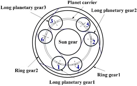
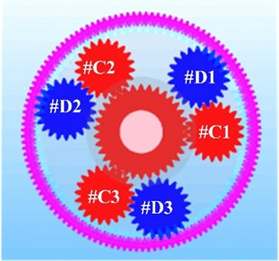
The SIMPACK software is used to establish the multi-body dynamics model of a planetary gear system. The geometric parameters of support bearings of planetary gears 1, 2 and 3, support bearings of planetary gears 4, 5 and 6, and support bearing of sun gear are listed in Table 1. Figure 1 is a lateral view of the planetary gear transmission system modeled by using the SIMPCAK software.
Fig. 1Schematic diagram of the a) structure and b) lateral view of the dynamic model of the planetary transmission system
a)
b)
Table 1The geometric parameters of the support bearings
Parameters | Long planetary gear | Short planetary gear | Sun gear |
Type | CRB | CRB | ACB |
Rolling elements’ number | 50 | 50 | 20 |
Pitch diameter / mm | 40.57 | 40.57 | 170.034 |
Roller diameter / mm | 2.6 | 2.6 | 13 |
Groove radius of inner raceway / mm | 6.612 | ||
Groove radius of outer raceway / mm | 6.238 | ||
Radial clearance / μm | 50 | 32.5 | |
Damping factor (Ns/m) | 500 | 500 | 500 |
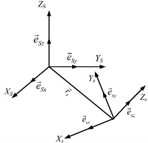
Fig. 2The parts coordinate systems used in the planetary gear system
When the planet gear has the errors, the transmission error’s peak occurs when the projection of the two gear errors on the engagement line is the maximum or minimum. Then, the transmission error of the system will be maximum or minimum; the vibration is the most intense; and the uneven load phenomenon is the most serious. In this paper, the errors in the direction of the meshing line are considered in all typical working conditions. The system power is input by using the ring gear 1. When the ring gear 1 rotates counterclockwise, the directions of meshing lines of all gear mechanisms in the composite planetary row are shown in the dotted line in Fig. 1(a). The long planet gears numbered 1, 2 and 3 are corresponds to the #C3, #C1, and #C2 planetary gears in Fig. 1(b), respectively. The short planet gears numbered 4, 5, and 6 are corresponds to the planetary gears #D3, #D1, and #D2 in Fig. 1(b), respectively.
In Fig. 2, the displacement vectors of the parts of the planetary gear system are defined by three Cartesian coordinates. The origin of Cartesian coordinates is the center of mass of the parts of the planetary gear system, such as the gears and carrier. In the global coordinate system of the planetary gear system, the position of part is given as [18]:
In Eq. (1), is the displacement vector of the parts of the planetary gear system; , , and are the basis vectors of the parts of the system; ,, and are the basis vectors of the mass centers of the parts in the origin coordinates; , , and are respectively the position of the center of mass of each part in the direction of the corresponding coordinate axis.
According to the Euler angle formula, the rotation matrix of the planetary gear system can be expressed by [18]:
The relative displacement vector is represented by six coordinates vectors. Its expression is [18]:
where , and are the rotational Euler angles of the part around the corresponding axials. As shown in Fig. 5, the part is in the global coordinate system and rotates in the local coordinate system (, , ).
The translational velocity and angular velocity of each part at six degrees of freedom can be respectively expressed by [18]:
where represents the Jacobian matrix of the part’s translation velocity; represents the angular velocity; and is the rotational velocity’s Jacobian matrix, which can be expressed by [18]:
The freedom of motion and angular velocity of the parts are expressed by the constraints between the parts. When the system contains parts and constraints, the degree of freedom of the independent generalized coordinate system can be calculated by .
The dynamics equation of the planetary gear system can be calculated by using the Newton-Euler equation, which is given as [18]:
where is the coordinate vector of the part; is the quality matrix of parts; is the force matrix acting on the part; and are the constraint matrix and binding force of parts respectively. The th part’s Euler equation can be expressed as [14]:
where is the moment of inertia of part ; is the part’s angular acceleration relative to the center of mass; is the part’s angular velocity relative to the center of mass; is the torque applied to the part. Part in this paper includes two ring gears, carrier, sun gear, and six planetary gears of the planetary gear system model as shown in Fig. 1.
In the transmission of the planetary gear system, there is not only external excitation caused by the changes of input torque and output load. In this paper, the influence of the time-varying meshing stiffness is considered. Considering the influence of meshing force , the bending, shearing and axial compression deformation elastic potential energy of the gear teeth along the tooth height can be expressed as [20]:
where, , , and are the stiffness of the bending, shearing, and axial compression deformation of the tooth along the meshing line respectively. , , and are the work done by the meshing force along the meshing line respectively equivalent to the elastic potential energy caused by the tooth bending deformation, shear deformation, and axial compression deformation.
The potential energy generated by the bending, shearing, and axial compression deformation of gear teeth under the action of is given as [20]:
where , , and are given as [20]:
where is the meshing force perpendicular to the tooth surface; represents tooth thickness’s half at the point that the meshing force acts on the gear; is the angle between the direction of the tooth thickness and the meshing force; is the distance between the acting position of meshing force and the fixed part of the tooth root circle; and are the width and length of the micro-section at a position that has the length of away from the meshing force action. According to Eqs. (9)-(11), the bending stiffness , shear stiffness , and axial compression stiffness can be expressed as [3]:
In Eqs. (10)-(14), and represent the elastic modulus and shear modulus of the material respectively. and represent the moment of inertia and the area of the section where is away from the meshing force point, respectively.
The elastic contact deformation occurs to the contact tooth surface when the teeth are engaged, and the contact stiffness is given as [3]:
The meshing stiffness is also affected by the deformation of the gear body to a certain extent. The calculation expression of its deformation can be expressed as [20]:
where is the tooth width. is the distance between the intersection of the meshing force line and the middle line of the gear to the gear base circle, and is the arc length of a single tooth on the gear base circle.
Moreover, , , , and are coefficients, which can be expressed by [20]:
where, represents the coefficients , , , and . and are the radii of the base circle and the inner radius of the gear. is the central angle of a single tooth. The values of , , , , , and are listed in Table 2.
The equivalent stiffness of the engagement line caused by the deformation of the wheel body can be expressed as [20, 21]:
Based on the equivalent stiffness on the meshing line corresponding to the tooth bending deformation, shear deformation, axial compression deformation, Hertz contact deformation, and wheel body deformation mentioned above, the single tooth meshing stiffness of the external meshing gear pair can be expressed as [20]:
Although the lubrication conditions will affect the contact characteristics of the meshing bodies as given in Ref. [22], it is difficult to formulate the lubrication conditions in the numerical model. Thus, the lubrication conditions are not considered in the proposed numerical model.
Table 2The coefficient values in Eq. (17)
5.5×10⁻⁵ | 2×10⁻³ | 2.32×10⁻⁴ | 4.8×10⁻³ | 0.027 | 6.805 | |
60×10-5 | 28×10-3 | 83×10-4 | 10×10-3 | 0.162 | 0.909 | |
51×10-5 | 186×10-3 | 0.051×10⁻⁴ | 53×10-3 | 0.290 | 0.924 | |
6.2×10⁻⁵ | 9.1×10⁻³ | 4.1×10⁻⁴ | 7.8×10⁻³ | 0.147 | 0.690 |
3. Eccentricity error modeling method
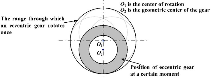
The eccentricity error of a planetary wheel refers to the distance between the center of rotation of a planetary gear and the geometric center, as shown in Fig. 3. The eccentricity error of the planetary gear is projected onto the meshing line of the planetary gear and the sun gear, which is given as:
The eccentricity error of the planetary gear is projected onto the meshing line of the planetary gear and the ring gear, which is given as:
where is the eccentricity error of the planetary gear; is the angle between the th planetary gear and the horizontal axis; is the angle between the initial phase vector of the planetary wheel and the horizontal axis; is the angle between the meshing line of planetary gear and sun gear and the horizontal axis; and is the angle between the meshing line of planetary gear-ring gear and the horizontal axis. is the rotation speed of the planetary wheel relative to the carrier.
The eccentricity errors of the sun gear and the planet gear will cause the geometric center of the rotating part, which cannot coincide with the rotating center. Therefore, the mismatch between the geometric center and the rotating center is realized by shifting the rotating part to simulate the machining error. The modeling schematic of the eccentricity error is shown in Fig. 4. Here, is the center of rotation; while is the geometric center of the gear.
Fig. 3Planetary gear eccentricity error projection to mesh line
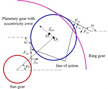
Fig. 4Modeling method of the gear eccentricity error
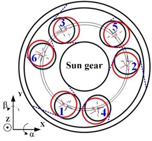
The eccentricity error of the planetary gears is shown in Fig. 5. The planetary gear 1 is close to ring gear 1 along the engagement line. The planetary gear 2 and the planetary gear 3 approaches the sun gear along the meshing line. The shaft hole of the planetary gear 4 is close to the planetary gear 1 along the meshing line. The shaft hole of the planetary gear 5 is close to the planetary gear 2 along the meshing line. The shaft hole of the planetary gear 6 is close to the ring gear 2 along the meshing line. In this paper, the range of the eccentricity error of planetary gears is from 10 μm to 80 μm.
Fig. 5Eccentricity error of the gear in the planetary gear transmission system
4. Numerical analysis
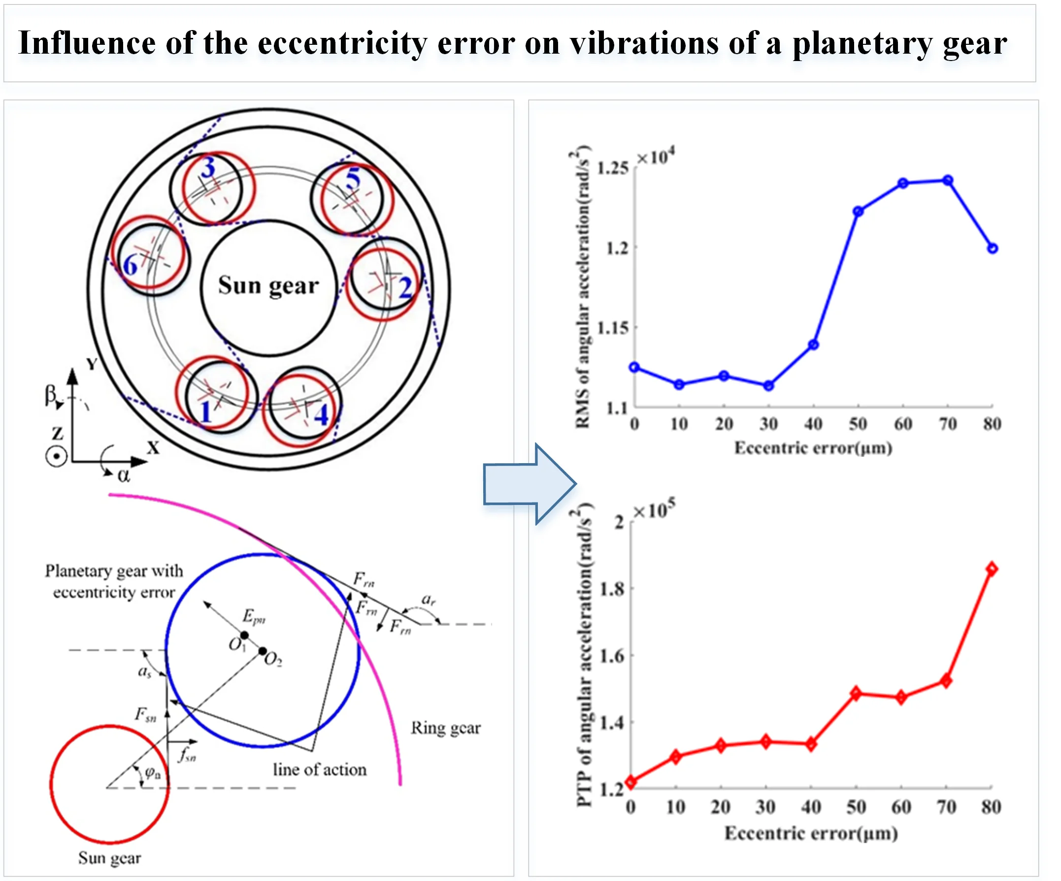
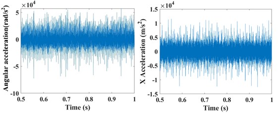
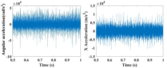
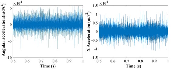
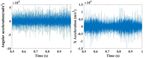
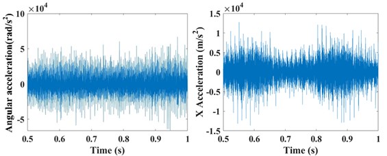
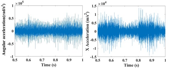
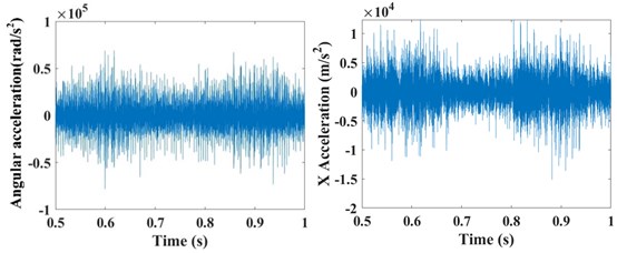
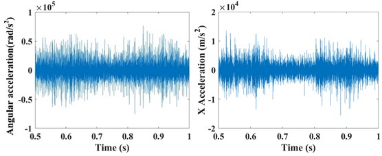
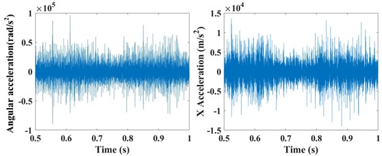
The input rotation speed of ring gear 1 is defined as 121 rad/s and 378 rad/s, respectively. The vibrations of the ring gear 2 are simulated and analyzed. The eccentricity errors of the six planetary gears are uniformly defined as 10 μm, 20 μm, 30 μm, 40 μm, 50 μm, 60 μm, 70 μm, and 80 μm. Figure 6 gives the angular acceleration around the -axis and translation acceleration along the direction of the ring gear 2 when the input speed is 121 rad/s and eccentricity errors from 0 μm to 80 μm on the planetary gears. It shows that the eccentricity errors can greatly affect the angular and translation accelerations of the planetary gear system. The relative statistical parameters will be compared in the following text.
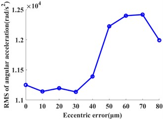
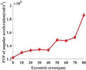
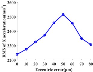
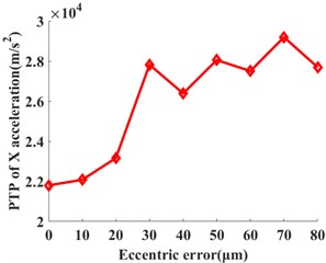
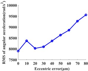
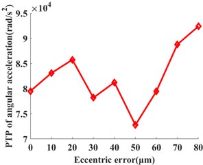
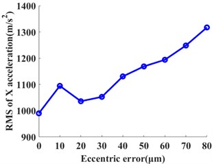
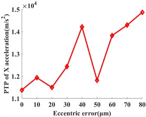
The statistical values including the root mean square value (RMS) and peak-to-peak value (PTP) is used. Those values have the reference values for the vibration intensity and vibration amplitude. They are calculated under each eccentricity error case. The influences of the multiple eccentricity error orders on the vibrations of planetary gear systems are analyzed. Figures 7 and 8 show the planetary gear eccentricity error’s impact on the statistics of the ring gear 2 when the input speed is 121 rad/s and 378 rad/s. In Figs. 8 and 9, the PTP values of angular acceleration and radial acceleration along with the direction increase with the eccentric errors when the input speed is 121 rad/s. But the RMS values of angular acceleration and radial acceleration along with the direction increase; and then it decreases with the increase of the eccentric error of planetary gear. The RMS values will reach the maximum one when the eccentricity error is from 50 μm to 60 μm. When the input speed is 378 rad/s, the RMS and PTP values of angular acceleration and radial acceleration along with the direction increase with the increase of the eccentric error; but the PTP values fluctuate from 20 μm to 60 μm. Due to the above results, the vibrations of the ring gear are greater when the input speed is 121 rad/s than those of 378 rad/s.
Fig. 6The angular acceleration around the Z-axis and translation acceleration along the X direction of the ring gear #2 when the input speed is 121 rad/s with the influences of the planetary gear eccentricity errors of a) 0 μm, b) 10 μm, c) 20 μm, d) 30 μm, e) 40 μm, f) 50 μm, g) 60 μm, h) 70 μm, and i) 80 μm
a)
b)
c)
d)
e)
f)
g)
h)
i)
Fig. 7The influences of the planetary gear eccentricity errors on the statistics of the ring gear 2 when the input speed is 121 rad/s. a) RMS of angular acceleration around the Z-axis, b) PTP of angular acceleration around the Z-axis, c) RMS of X acceleration, and d) PTP of X acceleration
a)
b)
c)
d)
Fig. 8The influences of the planetary gear eccentricity errors on the statistics of the ring gear 2 when the input speed is 378 rad/s. a) RMS of angular acceleration around the Z-axis, b) PTP of angular acceleration around the Z- axis, c) RMS of X acceleration, and d) PTP of X acceleration
a)
b)
c)
d)
5. Conclusions
To analyze the influence of the eccentricity error on the planetary gear transmission system with six planetary gears, a dynamic model of the planetary gear transmission system with the eccentricity error is proposed. The analysis results may give a new method to detect errors in the planetary gear system. The conclusions are as follows:
1) The PTP values of the angular accelerations and accelerations along the direction of the ring gear of the planetary gear transmission system increase with the increment of the eccentricity errors of the planetary gear.
2) The RMS values will increase with the eccentricity error when the input speed is 378 rad/s. When the input speed is 121 rad/s, the RMS values will reach the maximum value when the eccentricity error is from 50 μm to 60 μm; and then they decrease with the increment of the eccentricity error.
References
-
A. Moshrefzadeh and A. Fasana, “Planetary gearbox with localised bearings and gears faults: simulation and time/frequency analysis,” Meccanica, Vol. 52, No. 15, pp. 3759–3779, Dec. 2017, https://doi.org/10.1007/s11012-017-0680-7
-
Z. Shi, J. Liu, H. Li, Q. Zhang, and G. Xiao, “Dynamic simulation of a planet roller bearing considering the cage bridge crack,” Engineering Failure Analysis, Vol. 131, p. 105849, Jan. 2022, https://doi.org/10.1016/j.engfailanal.2021.105849
-
J. Liu, R.-K. Pang, H.-W. Li, and J. Xu, “Influence of support stiffness on vibrations of a planet gear system considering ring with flexible support,” Journal of Central South University, Vol. 27, No. 8, pp. 2280–2290, Aug. 2020, https://doi.org/10.1007/s11771-020-4449-0
-
J. Liu, L. Wang, J. Ma, W. Yu, and Y. Shao, “A multi-body dynamic study of vibration of a planetary gear train with the planetary bearing fault,” Proceedings of the Institution of Mechanical Engineers, Part K: Journal of Multi-body Dynamics, Vol. 233, No. 3, pp. 677–695, Sep. 2019, https://doi.org/10.1177/1464419319832485
-
Y. Huangfu, K. Chen, H. Ma, X. Li, H. Han, and Z. Zhao, “Meshing and dynamic characteristics analysis of spalled gear systems: A theoretical and experimental study,” Mechanical Systems and Signal Processing, Vol. 139, p. 106640, May 2020, https://doi.org/10.1016/j.ymssp.2020.106640
-
S. Xue and I. Howard, “Vibration response from the planetary gear with flexible ring gear,” International Journal of Powertrains, Vol. 8, No. 1, pp. 3–22, 2019, https://doi.org/10.1504/ijpt.2019.098108
-
H. Li, J. Liu, J. Ma, and Y. Shao, “Effect of the radial support stiffness of the ring gear on the vibrations for a planetary gear system,” Journal of Low Frequency Noise, Vibration and Active Control, Vol. 39, No. 4, pp. 1024–1038, Dec. 2020, https://doi.org/10.1177/1461348419844642
-
J. Wei et al., “A coupling dynamics analysis method for a multistage planetary gear system,” Mechanism and Machine Theory, Vol. 110, pp. 27–49, Apr. 2017, https://doi.org/10.1016/j.mechmachtheory.2016.12.007
-
J. Zhang, W. Sui, and J. Dhupia, “A simplified formulation to estimate influence of gearbox parameters on the rattle noise,” Sound and Vibration, Vol. 53, No. 2, pp. 38–49, 2019, https://doi.org/10.32604/sv.2019.04362
-
C. Liu, C. G. Cooley, and R. G. Parker, “Parametric instability of spinning elastic rings excited by fluctuating space-fixed stiffnesses,” Journal of Sound and Vibration, Vol. 400, pp. 533–549, Jul. 2017, https://doi.org/10.1016/j.jsv.2017.03.043
-
X. Wang, Q. Zhao, T. Li, and H. Zhang, “Analysis of coupling fault correlation and nonlinear vibration of multi-stage gear transmission system,” Journal of Vibroengineering, Vol. 23, No. 1, pp. 114–126, Feb. 2021, https://doi.org/10.21595/jve.2020.21561
-
J. Liu, R. Pang, S. Ding, and X. Li, “Vibration analysis of a planetary gear with the flexible ring and planet bearing fault,” Measurement, Vol. 165, p. 108100, Dec. 2020, https://doi.org/10.1016/j.measurement.2020.108100
-
J. Liu and Y. Shao, “Dynamic modeling for rigid rotor bearing systems with a localized defect considering additional deformations at the sharp edges,” Journal of Sound and Vibration, Vol. 398, pp. 84–102, Jun. 2017, https://doi.org/10.1016/j.jsv.2017.03.007
-
J. Liu and Y. Shao, “An improved analytical model for a lubricated roller bearing including a localized defect with different edge shapes,” Journal of Vibration and Control, Vol. 24, No. 17, pp. 3894–3907, Sep. 2018, https://doi.org/10.1177/1077546317716315
-
J. Liu, C. Tang, H. Wu, Z. Xu, and L. Wang, “An analytical calculation method of the load distribution and stiffness of an angular contact ball bearing,” Mechanism and Machine Theory, Vol. 142, p. 103597, Dec. 2019, https://doi.org/10.1016/j.mechmachtheory.2019.103597
-
J. Liu, Y. Xu, and G. Pan, “A combined acoustic and dynamic model of a defective ball bearing,” Journal of Sound and Vibration, Vol. 501, p. 116029, Jun. 2021, https://doi.org/10.1016/j.jsv.2021.116029
-
J. Liu, “A dynamic modelling method of a rotor-roller bearing-housing system with a localized fault including the additional excitation zone,” Journal of Sound and Vibration, Vol. 469, p. 115144, Mar. 2020, https://doi.org/10.1016/j.jsv.2019.115144
-
J. Liu, S. Ding, R. Pang, and X. Li, “Influence of the roller profile modification of planet bearing on the vibrations of a planetary gear system,” Measurement, Vol. 180, p. 109612, Aug. 2021, https://doi.org/10.1016/j.measurement.2021.109612
-
X. Fang et al., “SIMPACK dynamics analysis basic,” Southwest Jiaotong University, 2008.
-
Z. Chen and Y. Shao, “Dynamic simulation of spur gear with tooth root crack propagating along tooth width and crack depth,” Engineering Failure Analysis, Vol. 18, No. 8, pp. 2149–2164, Dec. 2011, https://doi.org/10.1016/j.engfailanal.2011.07.006
-
J. Liu, C. Tang, and G. Pan, “Dynamic modeling and simulation of a flexible-rotor ball bearing system,” Journal of Vibration and Control, p. 107754632110343, Jul. 2021, https://doi.org/10.1177/10775463211034347
-
J. Liu and Z. Xu, “A simulation investigation of lubricating characteristics for a cylindrical roller bearing of a high-power gearbox,” Tribology International, Vol. 167, p. 107373, Mar. 2022, https://doi.org/10.1016/j.triboint.2021.107373
About this article

Supported by the National Natural Science Foundation of China (No. 52175120, 51975068 and 52211530085).
