Abstract
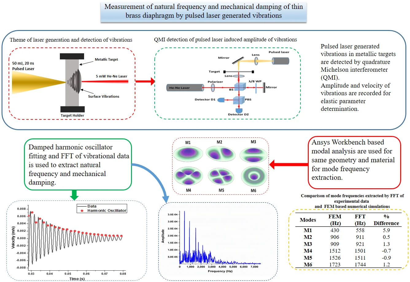
Damped harmonic oscillator model based fitting of nanosecond pulsed laser induced amplitude variations of clamped vibrating circular plate is used to estimate the mechanical damping and natural frequency of the sample in current work. Laser Pulses of 50 mJ energy, 20 ns duration, and focused at a spot of 4 mm diameter at the center of the circular thin brass sheet of 100 µm thickness is used to generate vibrations in the target. Quadrature Michelson interferometer (QMI) with CW laser focused on the opposite side of the target surface is used to measure the amplitude of vibrations. Variations of fringe frequencies are identified in the frequency domain. Finite element based numerical modal analyses are also performed in ANSYS Workbench for the verification of experimental results for the same geometry and materials. Experimental frequencies of vibrations are found to match nearly 2 percent of FEM modes. Moreover, Elastic parameters are also found using the first two mode frequencies and a reasonable agreement is observed while comparing with the elastic parameter data of brass. Current work in itself is a unique attempt of getting mechanical parameters for the determination of elastic parameters in a single laser pulse impulse excited measurement for thin clamped targets.
Highlights
- Elastic parameters of fully clamped thin brass diaphragm are determined by using vibrational parameters.
- Quadrature Michelson interferometer (QMI) is used for the recording of nanosecond pulsed laser generated vibrations in the diaphragm target.
- Damped harmonic oscillator based fitting of velocity of vibration data is used for the extraction of resonance frequencies and mechanical damping.
- Fast Fourier transform (FFT) based frequency response of data is compared with numerically determined mode frequencies for same material and geometry in Ansys Workbench.
1. Introduction
Fully clamped thin metallic plates are used in different fields of engineering and science for conversion of pressure or momentum in measurable electrical or electronic signals in transducers [1], regulation of pressure in pneumatic systems, separation of fluids and predictable failure points as rupture discs for overpressure protections [2], [3]. Thin metallic discs are used as deforming or vibrating objects under applied dynamic loads [4]. Sensitive applications require isotropic and elastic materials with linear behavior under dynamic loading conditions for the precise detection and conversion of smaller changes into useable signals for feedback and control [5]. Mechanical parameters like natural frequency, damping constants, and stiffness coefficients are the governing parameters of oscillatory behavior under dynamic loading [6],[7]. These mechanical parameters are directly related to the geometry and material properties like density and elastic moduli. As measurable quantities, these parameters can be used to determine elastic properties [8].
Ultrasonic techniques (UT), Resonance Ultrasound Spectroscopy (RUS), and Impulsed Excitation Techniques (IET) are commonly used for the determination of the elastic properties of the materials. Piezoelectric based ultrasonic techniques are used in the pulse-echo mode for the determination of elastic parameters. The disadvantage of the application of these techniques lies in the coupling of transducers to the vibrating surfaces and altering of the motion pattern (frequencies) by mass loading of the samples. Application to remote surfaces and at elevated temperatures is also difficult. Pulsed laser generated ultrasounds are the alternative to all these problems, as these can be used remotely even at higher temperatures without mass loading the surfaces [9]. Different types of surface waves are generated depending on the pulse duration and thickness of materials. But complexity in the application of pulsed laser generated ultrasounds lies in the broadband signal generation, the existence of different modes of lamb waves for thin sheets, and the presence of Rayleigh wave. All these problems require special arrangments either for the selection of laser generated ultrasonic frequencies or complex analysis algorithms for the identification of different mode velocities.
Alternatively, resonance frequencies are measured by excitation of ultrasounds in the material with an applied sweep of load frequencies in RUS. Theoretical or previously measured resonance frequencies are also required for matching with the experimentally measured frequencies in RUS [10]. The success of RUS lies in the preparation of the sample and iterative matching of the experimentally measured and theoretically available frequency response of materials in inverse mode. With the increased computational and best available numerical fitting procedures, accuracy in RUS predicted results are still questioned and also requires error prediction frameworks [11].
Measurement of mechanical damping and resonance frequencies of flexural and torsional modes separately in IET [12] is also used to determine the elastic properties of different types of materials [13]. Fast Fourier Transformation (FFT) based frequency response, Finite Element Method (FEM) based numerical and complex empirical relations are used in RUS and IET for the determination of parameters that are restricted to certain geometries, sample sizes, and free boundary conditions [12], [13]. IET requires the sample to hold in free vibration without clamping with certain predefined dimensional and boundary conditions. Elimination of the requirement of frequency response data before the experiment and simplification of sample preparation with the implementation of constraints encourages new procedures and techniques.
Measurement of oscillations of thin vibrating surfaces can be used for the determination of mechanical parameters. Damped harmonic oscillator model is a physical model that relates natural frequencies, mechanical damping and stiffness of a vibrating surface [6]. Vibrations are generated on a surface under the influence of impulsive or dynamic loadings. Different types of mechanical hammers and piezoelectric transducers are conventionally used as contact based vibration generators [12]. Short duration laser pulse focused on the surface of the target can also induce vibrations without any contact. When the laser pulse interacts with the solid, energy is absorbed by the surface electrons and then transferred to the lattice. The material gets ionized and plasma is generated if the electric field associated with the pulse is greater than the breakdown limit (ablation regime). In this case, strong longitudinal waves are generated on the opposite side of the laser interaction point as a reaction to material removal. On the other hand fluence below the evaporation limit introduces several thermal effects (thermo-elastic regime) like heating, electronic and vibrational excitation, and elastic stresses [14]. Continuous waveform (CW) laser interferometers are employed in nondestructive testing (NDT) [15], [16] as an alternative to the piezoelectric and electromagnetic recording of vibrations. Quadrature Michelson interferometer (QMI) is an attractive choice for the reduction of measurement error, simplicity of application, and ability to identify forward and backward motion of surface [17]-[19].
Complexity in data analysis algorithms in ultrasonic techniques, prior requirement of known elastic moduli of target material with free holding condition in RUS and application of IET only to free thick samples are identified as areas which can be further explored to measure elastic parameters more accurately with less effort and independent of special geometrical arrangements. Non-contact and remote measurement of mechanical parameters for the determination of elastic properties of the clamped thin vibrating sheets in single measurement is the main objective and uniqueness of current work. Harmonic oscillator model based fitting of velocity variations of the vibrating surface is used in current work for the determination of mechanical damping and natural frequencies in a single high energy laser pulse excitation and measurement.
2. Materials and methods
A high energy laser pulse impulse generated vibrations, laser interferometeric measurement of vibrations and damped harmonic oscillator model fitting based frequency response measurements are used for the determination of mechanical parameters. First few modes of vibrations and mechanical damping is measured for thin circularly clamped brass target for the determination of elastic parameters. Finite element based simulation of same geometry and material are also performed for the verification of results. The maximum amplitude of vibrations are expected near natural frequencies of a sample which are measured by QMI. Data of vibration of pulsed laser impulse excitation is converted into velocity variation of a vibrating surface by using frequency domain conversion. Vibration frequencies are identified from velocity variation data. Higher modes of vibrations are independently extracted from data and verified from FFT of the recorded vibrations. Finally, finite element based simulations of ANSYS Workbench are used to estimate the remaining elastic parameters.
Single laser pulse of 20 ns duration and 50 mJ energy is used to excite vibrations in a circualrly clamped brass target. Brass target of 48 mm diameter with 100 µm thickness is clamped in a cirular aluminum holder with 40 mm internal free diameter and with 16 mm thickness as shown in Fig. 1(b). Effective vibrating diameter of brass target is 40 mm. Laser pulse is focused at the center of the circular target by a plano convex lens of 200 mm focal length and 25 mm diameter to a spot size of 4mm diameter. Calculations are performed for the generation of maximum amplitude of vibrations with minimum of material removal and damage to surface. Further reduction in diameter of laser spot size can increase the ablation of material with increased amplitude of vibration.
Pulsed laser source with target surface placed as a mirror in one arm of QMI as a path length changer is shown in Fig. 1(a). Beam from a polarized 5 mW, CW He-Ne laser of 20-30 cm coherence length is split into a reference and target beam which is going to target after passing through a /8 wave plate and focusing lens. Interference of linearly polarized and circularly polarized laser beams are used to form quadrature signal with two 90° out of phase interference signals. Polarization beam splitter is also used to extract two 90° out of phase interference signals. Two photo detectors are used to record intensity variations of interference fringes proportional to displacement of surface from rest position as shown in later section.
Fig. 1a) QMI based vibration measurement setup b) simulated aluminum holder with circular brass sheet at the center

a)

b)
QMI with CW laser focused at the target is used for the measurement of the amplitude of vibrations. This amplitude of vibrations is converted into intensity variations in the form of fringes of dark and bright light variations recorded by photo detectors and data acquisition system. Each fringe of intensity variation corresponds to /2 path length change of two arms of the interferometer. Vibration of surface is used as a source of path length changer. Higher fringe counts is expected corresponding to the increased amplitude of vibration. Fringe variations with respect to time are identified as fringe frequencies by using Short Time FFT or Wavelet Transform (WT) analysis. This fringe frequency is directly converted into velocity variations of surface movement by multiplying with /4. The velocity variation data is fitted iteratively by the damped harmonic oscillator model of Eq. (1) for the estimation of natural frequency and damping constant from fundamental frequency to higher mode frequencies. Here is the damping factor, is the angular frequency and is the constant:
Natural frequencies, velocity of sound waves in material, and geometry consideration for vibrating circular sample clamped at the boundary are described in the literature [20] and presented in Eq. (2) and Eq. (3). Here, thickness of sample , radius of sample , density , Poisson ratio, Young’s modulus , and speed of waves in material are the parameters used in equations:
Poisson ratio is calculated by using two mode frequencies [21] extracted from the fitting of harmonic oscillator model with higher frequencies to initial vibration data as shown in Eq. (4) and Eq. (5):
where, , are modes with , mode frequencies respectively (in Hz), is the gyration radius of circular disk. Shear modulus is calculated from the Eq. (6):
FFT of recorded vibrational data is further used to verify the higher modes of vibrations. FEM based model analysis of circularly clamped 100 µm thick brass discs is also performed in ANSYS Work bench for the estimation of mode frequencies. Iterative approach in selection of material properties is used in model analysis to match the experimentally determined and numerically estimated frequencies.
3. Results and discussions
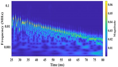
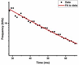
Pulsed laser induced vibrations in the brass target are converted into intensity variations by QMI and presented in Fig. 2. Fringe frequency or intensity variations corresponding to amplitude variations of vibrating surface are identified by wavelet transform of data and scalogram as shown in Fig. 3(a). Selected data points from the peak frequency variations are further fitted exponentially and shown in Fig. 3(b). The decay in the fringe frequency is exponential which shows the reduction in amplitude of vibration due to the effect of internal mechanical friction. Fringe frequency data is converted into velocity variation data in time domain by multiplying with /4, where is the wavelength of CW laser source of interferometer. Fig. 4 shows velocity variations of sample surface for 50 mJ pulsed laser energy.
Fig. 2Intensity variation of pulsed laser induced vibrations of circular brass plate measured by QMI, bursts of intensity variations represents variation in fringes with respect to time (Fringe Frequency)
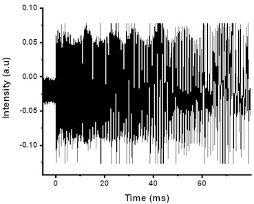
Fig. 3a) Scalogram of fringe frequency, b) exponential fitting of peak fringe frequency variation
a)
b)
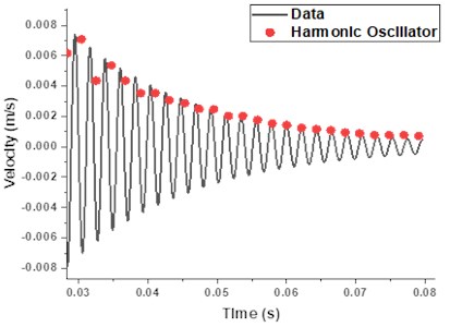
Data of velocity variation is fitted by damped harmonic oscillator model of Eq. (1) for the determination of natural frequencies and damping constants of vibrating surfaces and shown in Fig. 4. Natural frequencies in the range of 458±10 Hz and damping factor of 55±2 (N-s/m) with 1.2×10⁻⁵ are estimated. Measured mode frequency is in closed agreement with FEM based fundamental mode frequency presented in Table 1.
Table 1Comparison of Mode frequencies extracted by FFT of experimental data and FEM based numerical simulations
Modes of vibration | Brass sheet mode frequency from FEM (Hz) | Modes frequencies FFT of experimental data (Hz) | % Difference of FEM and experimental |
M1 | 430 | 458 | 5.9 |
M2 | 906 | 911 | 0.5 |
M3 | 909 | 921 | 1.3 |
M4 | 1512 | 1501 | –0.7 |
M5 | 1526 | 1511 | –0.9 |
M6 | 1723 | 1744 | 1.2 |
Relation between the velocities of sound waves in material with Young’s modulus is extracted from equation of motion as given in Eq. (2) and Eq. (3). Data of natural frequency 458 Hz, thickness of sheet 0.1 mm and radius of circular target 20 mm is used in Eq. (2) for the estimation of sound velocity and found out to be 3860 m/s. Poisson ratio 0.36 is calculated from Eq. (4) with = 458 Hz and = 897 Hz as mode frequencies extracted higher harmonic oscillator fitting of data. Young’s modulus is calculated from Eq. (3) by using , with density 8750 kg/m3, Poisson ratio of 0.36 and found out to be 114.5 GPa. Shear modulus of 42.2 is calculated from Eq. (6).
Fig. 4Damped harmonic oscillator model fit of velocity vibration data of brass disc for the determination of natural frequency 458±10 (Hz) and damping constants 55±2 (N-s/m)
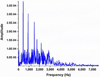
Fast Fourier Transform (FFT) of experimental data of 50 mJ pulsed laser excited vibrations in brass target is shown in Fig. 5. First six modes of vibrations for impulse excited circular target are also presented in third column of Table 1. These mode frequencies are presented for the verification of harmonic oscillator based fitted frequencies and comparison with the numerically calculated frequencies. Only lowest mode frequencies are presented which dominates the FFT.
Fig. 5FFT of data for the comparison of modes of vibrations
FEM based modal analysis are also performed for the estimation of natural frequencies of circular brass target of 100 µm thickness with 20 mm radius with fixed boundary constraints. Elastic parameter values for Young’s modulus = 110 GPa, Poisson ratio = 0.35 and shear modulus = 41 GPa are used in FEM based numerical calculation in ANSYS Workbench. Results of first six mode frequencies are shown in Fig. 6 and presented in Table 1. Difference between experimentally measured and actual material values (provided by vendor) of elastic parameters is found to be less than 5 % for Young’s modulus, 3 % for Poisson ratio and shear modulus. Nearly the same 5.9 % difference is also present in the measured and numerically calculated first mode frequency suggesting the slightly lower values used in theoretical calculation.
Percentage difference between FEM and experimental frequencies are placed in fourth column of Table 1. The % difference in first mode frequency of vibration is observed to be 5.9 %, while differences of all other mode frequencies are close to 1 %. Only first six mode frequencies are used for the confirmation of experimental results and verification of measured values. It can be seen that the FEM based estimated first frequency mode is 5.9 % lower than experimentally measured value. Most experimental measured frequencies are higher than the corresponding FEM based estimated values. This difference in the measured values can be related with the slight alteration of surface area due to physical clamping. As first mode frequency is more dependent on the surface area, so larger difference was observed. Secondly, some measurement errors like uncertainty in measured dimensions and thickness are propagated in experimentally measured values which affected the results whereas, the numerical calculations in FEM have no such uncertainties.
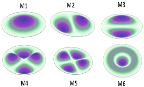
Fig. 6First six modes of vibration M1 to M6 of a thin sheet of 100 µm thickness and 44 mm diameter circularly clamped brass sheet at the edges, simulated by FEM with density = 8750 kg/m3, Poisson ratio = 0.35 and Young’s modulus = 110 GPa
4. Conclusions
Noncontact single measurement impulse excitated vibration based procedure is presented in current work for the measurement of mechanical vibrational parameters of fully clamped thin metallic target. Presented procedure is used as an alternative to ultrasonic and RUS techniques. Young’s modulus, shear modulus and Poisson ratio are also estimated by using measured vibrational parameters.
Single high energy nanosecond laser pulse and QMI is used to measure vibration frequencies as intensity variations. Damped harmonic oscillator model fitting frequency response is used initially for fitting vibrational data to estimate the mode frequencies and damping constant. These frequencies are further verified by FEM based mode shapes and mode frequencies. Damped harmonic model is used successfully for the determination of fundamental natural frequency and mechanical damping of material. First six fundamental mode frequencies are used to verify the measured results. A difference of 5.9 % is observed in fundamental frequency of vibrations for experimentally measured values. Youngs modulus of 114.5±4.5 GPa, Poisson ratio of 0.36±.01 and shear modulus of 42.2±1 GPa are estimated from measured frequency response.
Current technique of pulsed laser impulse excitation for fully clamped thin samples is found useful in estimation of elastic module using experimental data with simple analytical formulas. This technique can further be used for any type of vibrating surfaces. Current work can be used in the field for the remote determination of elastic parameters of materials even at elevated temperatures.
References
-
M. Gilbert, “Principles of pressure transducers, resonance, damping and frequency response,” Anaesthesia and Intensive Care Medicine, Vol. 13, No. 1, pp. 1–6, Jan. 2012, https://doi.org/10.1016/j.mpaic.2011.10.010
-
N. P. Cheremisinoff and P. Rosenfeld, “The petroleum industry,” in Handbook of Pollution Prevention and Cleaner Production – Best Practices in The Petroleum Industry, Oxford: William Andrew Publishing, 2009.
-
D. Wilkie and S. A. Fisher, “Measurement of temperature by Mach‐Zehnder interferometry,” ARCHIVE: Proceedings of the Institution of Mechanical Engineers 1847-1982 (vols 1-196), Vol. 178, No. 1963, pp. 461–472, Jun. 1963, https://doi.org/10.1243/pime_proc_1963_178_034_02
-
Z. You-He, Y. Kai-Yuan, and F. P. J. Rimrott, “Theory of vibrating diaphragm-type pressure sensor,” AIAA Journal, Vol. 32, No. 3, pp. 633–638, Mar. 1994, https://doi.org/10.2514/3.12031
-
M. Sayed, A. A. Mousa, and I. Mustafa, “Stability and bifurcation analysis of a buckled beam via active control,” Applied Mathematical Modelling, Vol. 82, pp. 649–665, Jun. 2020, https://doi.org/10.1016/j.apm.2020.01.074
-
H. J. Pain, The Physics of Vibrations. John Wiley and Sons, 1997.
-
M. Sayed and A. A. Mousa, “Vibration, stability, and resonance of angle-ply composite laminated rectangular thin plate under multiexcitations,” Mathematical Problems in Engineering, Vol. 2013, pp. 1–26, 2013, https://doi.org/10.1155/2013/418374
-
H. D. Lafta, “Experimental determination of elastic constant of composite materials using vibration properties,” Journal of Engineering and Sustainable Development, Vol. 17, No. 5, 2021.
-
C. Scruby and L. Drain, Laser Ultrasonic Testing and Applications. CRC press, 1990.
-
R. A. Adebisi, T. J. Lesthaeghe, M. R. Cherry, S. Sathish, and P. A. Shade, “Development of a LASER-based resonant ultrasound spectroscopy and a framework for error propagation in the estimated elastic moduli,” in 44th Annual Review of Progress in Quantitative Nondestructive Evaluation, Vol. 1949, 2018, https://doi.org/10.1063/1.5031626
-
D. Mounier, C. Poilâne, H. Khelfa, and P. Picart, “Sub-gigahertz laser resonant ultrasound spectroscopy for the evaluation of elastic properties of micrometric fibers,” Ultrasonics, Vol. 54, No. 1, pp. 259–267, Jan. 2014, https://doi.org/10.1016/j.ultras.2013.06.014
-
I. I. Popov and M. V. Shitikova, “Impulse excitation technique and its application for identification of material damping: An overview,” in IOP Conference Series: Materials Science and Engineering, Vol. 962, No. 2, p. 022025, Nov. 2020, https://doi.org/10.1088/1757-899x/962/2/022025
-
C. Boursier Niutta, “Enhancement of a new methodology based on the impulse excitation technique for the nondestructive determination of local material properties in composite laminates,” Applied Sciences, Vol. 11, No. 1, p. 101, Dec. 2020, https://doi.org/10.3390/app11010101
-
N. Hosoya, I. Kajiwara, and T. Hosokawa, “Vibration testing based on impulse response excited by pulsed-laser ablation: Measurement of frequency response function with detection-free input,” Journal of Sound and Vibration, Vol. 331, No. 6, pp. 1355–1365, Mar. 2012, https://doi.org/10.1016/j.jsv.2011.10.034
-
I. Kajiwara and N. Hosoya, “Vibration testing based on impulse response excited by laser ablation,” Journal of Sound and Vibration, Vol. 330, No. 21, pp. 5045–5057, Oct. 2011, https://doi.org/10.1016/j.jsv.2010.09.036
-
N. Hosoya, R. Umino, I. Kajiwara, S. Maeda, T. Onuma, and A. Mihara, “Damage detection in transparent materials using non-contact laser excitation by nano-second laser ablation and high-speed polarization-imaging camera,” Experimental Mechanics, Vol. 56, No. 2, pp. 339–343, Feb. 2016, https://doi.org/10.1007/s11340-015-0089-y
-
Heydemann and Peter L. M., “Determination and correction of quadrature fringe measurement errors in interferometers,” Applied Optics, Vol. 20, No. 19, p. 3382, Oct. 1981, https://doi.org/10.1364/ao.20.003382
-
A. P. Kuznetsov, “Quadrature laser interferometry in the pulsed plasma diagnostic,” in Journal of Physics: Conference Series, Vol. 666, No. 1, p. 012017, Jan. 2016, https://doi.org/10.1088/1742-6596/666/1/012017
-
L. H. V. Felão, R. I. Martin, J. M. S. Sakamoto, M. C. M. Teixeira, and C. Kitano, “Wide dynamic range quadrature interferometer with high-gain approach and sliding mode control,” Optics Express, Vol. 27, No. 18, p. 25031, Sep. 2019, https://doi.org/10.1364/oe.27.025031
-
Glenn Elert, “Simple Harmonic Oscillator,” in Understanding Acoustics: An Experimentalist’s View of Sound and Vibration, Cham: Springer International Publishing, 2021, pp. 59–131.
-
S. Chen, “Resonant frequency method for the measurement and uncertainty analysis of acoustic and elastic properties,” Ultrasonics, Vol. 38, No. 1-8, pp. 206–211, Mar. 2000, https://doi.org/10.1016/s0041-624x(99)00038-4
Cited by
About this article

