Abstract
During hard rock excavation in the process of tunnel construction, the hard rock excavator wears seriously and quickly and reduces its excavation efficiency. Aiming at this problem, this paper proposes a composite rock breaking method by impact rolling and cutting as a solution. In this paper, the composite rock breaking characteristics of impact hob are studied. The impact cutting load of the hob was analyzed, and the hobbing force equation and the rock crushing volume equation were established. The effects of different impact frequencies and impact loads on the cutting force and rock crushing characteristics of the hob were analyzed by experiments. The results show that under a certain thrust and hob spacing, with the increase of the impact frequency, the rock ridge between the two hobs gradually decreases, while the crushed volume of the rock increases gradually. Under the same axial load and cutter spacing conditions, with the increase of the impact frequency, the hob shear force decreases significantly. Under a certain axial load and impact frequency, with the increase of impact load, the crushing volume of rock and the hob shear force decrease significantly. These test results are of great significance for guiding the efficient excavation of hard rock tunnels.
Highlights
- In order to improve the efficiency of hard rock excavator, the composite rock breaking method by impact rolling and cutting was proposed.
- The impact cutting load of the hob was analyzed, and the hobbing force equation and the rock crushing volume equation were established.
- The effects of different impact frequencies and impact loads on the cutting force and rock crushing characteristics of the hob were analyzed by experiments.
- The test results show that, under certain impact frequency and impact load, the efficiency of the composite rock breaking method is significantly improved.
1. Introduction
When the roadheader is working at a hard granite formation, its hob seriously wears, so the cutter needs to be replaced once with an average footage of 3-5 m. The excavation efficiency is extremely low, and the consumption of the cutter accounts for the cost of the TBM machine for about 40 %. So the price is high. The disc hob, which is in direct contact with the rock and soil of the excavation face, is the core key component of TBM rock breaking, which is crucial to the rock breaking effect, boring speed and tool consumption. Exploring the wear law of TBM tools and developing high-efficiency hard rock excavation equipment has always been an important topic in the field of TBM [1-3].
In order to overcome the problem of serious hob wear during the excavation operation in hard rock formations, researchers have continuously optimized the layout of the hob, designed a large-diameter hob with excellent performance, and studied its wear law. Xia Yimin et al. established a calculation model of key parameters such as cutter arrangement, opening, and disc body design based on the boring geological conditions, cutter head structure parameters and boring parameters, and proposed a TBM cutter head geological adaptive design method [4-8]. The optimized design was provided and successfully applied to the engineering practice. Liu Jianqin et al. studied the crack initiation life of the dangerous point of TBM cutter head under different geological conditions, and proposed a geological matching calculation model of TBM cutter head based on crack initiation [9]. A large-diameter disc hob increases the allowable limit wear of the hob ring, and can use a larger hob bearing, which improves the wear life of the ring and the thrust bearing of the turret, thereby increasing the TBM tunneling speed. Aiming at the problem that the cluster DTH hammer cannot adjust the working airflow in time according to the rock formation conditions, and the working efficiency is low, Lou Lei et al. proposed an airflow adjustment mechanism, and studied the synchronization characteristics of the mechanism in detail to improve the working efficiency of the cluster DTH hammer [10]. In order to improve the service life of the TBM hob cutter ring in hard and highly abrasive formations, Jia Lianhui et al. studied the influence of the alloy composition of the cutter ring and the type and state of the wear-resistant structure on the wear resistance, and formulated a new TBM cutter ring material [11]. Xia Yimin et al. established a shield rock-breaking test bench and conducted a series of in-depth studies on the combined rock-breaking law and wear characteristics of the hob [12, 13]. Cheng Yongliang studied the rock-breaking characteristics of the hob at different installation angles, the hob installation angle with higher rock breaking efficiency is obtained [14]. The above research analyzes the tunneling efficiency of the roadheader from the perspectives of cutter head structure, cutter material, and hob installation method. Optimizing the structure of the cutter head and the installation angle of the hob, improving the strength of the tool material leads to a higher rock-breaking efficiency to a certain extent, but it does not fundamentally solve the problem of serious hob wear when the hob is excavating in a hard rock environment. For this reason, some scholars have carried out a related research on the rock properties to seek how to improve the rock breaking efficiency of the hob.
Cao Ping used a combination of numerical simulation and experiment to analyze the influence of different joint spacing and joint inclination on the hob rock-breaking characteristics , and obtained the higher rock-breaking efficiency of the hob [15, 16]. Du Lijie et al. conducted a granite wear test on a 20-inch disc hob, and the results showed that under the same conditions, the use of large-diameter disc hob had higher boring efficiency, but the tool wear rate from the center to the edge of the cutter disc still showed an increasing trend, with the increase of rock joints and fissures, the tool wear and consumption are gradually reduced [17]. Gong Qiuming et al. used experimental methods to study the impacts of hob spacing and confining pressure on the rock breaking performance of hob [18, 19]. T. Moon used the discrete element method to simulate numerically the hob rock-breaking characteristics under different parameters, and obtained the optimal combination of parameters for the hob's efficient rock-breaking [20]. Hadi Bejari analyzed the rock-breaking characteristics of the hob and the rock-breaking characteristics of different joint spacings and cutting directions. Rohola Hasanpour et al. used a numerical simulation to evaluate the TBM tunneling efficiency and rockburst occurrence conditions under unfavorable geological conditions, and studied the rock breaking characteristics of the hob under different confining pressures [22, 23]. The results showed that with the increase of confining pressure, the probability of rockburst increased, and the hob shear force increased too. On the basis of the theory of damage and deformation of the surrounding rock of the tunnel, Li Xibing proposed the non-explosive continuous mining method of induced cracking when studying the efficient mining of metal hard rock mines, and applied this method to the actual mining of Kaiyang phosphate mine [24, 25]. It greatly caused the improvement of the mining efficiency. The inherent joints and fissures in the rock can reduce hob wear and improve the rock breaking efficiency. The above research provides a useful reference for the efficient crushing of hard rock. But how to generate more damage inside the rock massif while the hob is rotating? This paper proposes a composite method of impact rolling and cutting to solve this problem.
In this paper, an impact hob cutting scheme is designed. The impact hob is used to impact and roll the rock out, the theoretical model of impact rolling shear is constructed, and the crushing characteristics of rock under the action of rolling shear load + impact load are analyzed. The influence of impact load on the rolling characteristics of the hob and the rock crushing volume was analyzed by simulation and experiment, and the rolling cutting and crushing laws of hard rock under different impact loads and frequencies were obtained. The research results of this paper provide a scientific basis for the efficient rock breaking of hard rock roadheaders.
2. Theoretical analysis of impact roll-cut composite rock breaking
2.1. Rock breaking by impact rolling
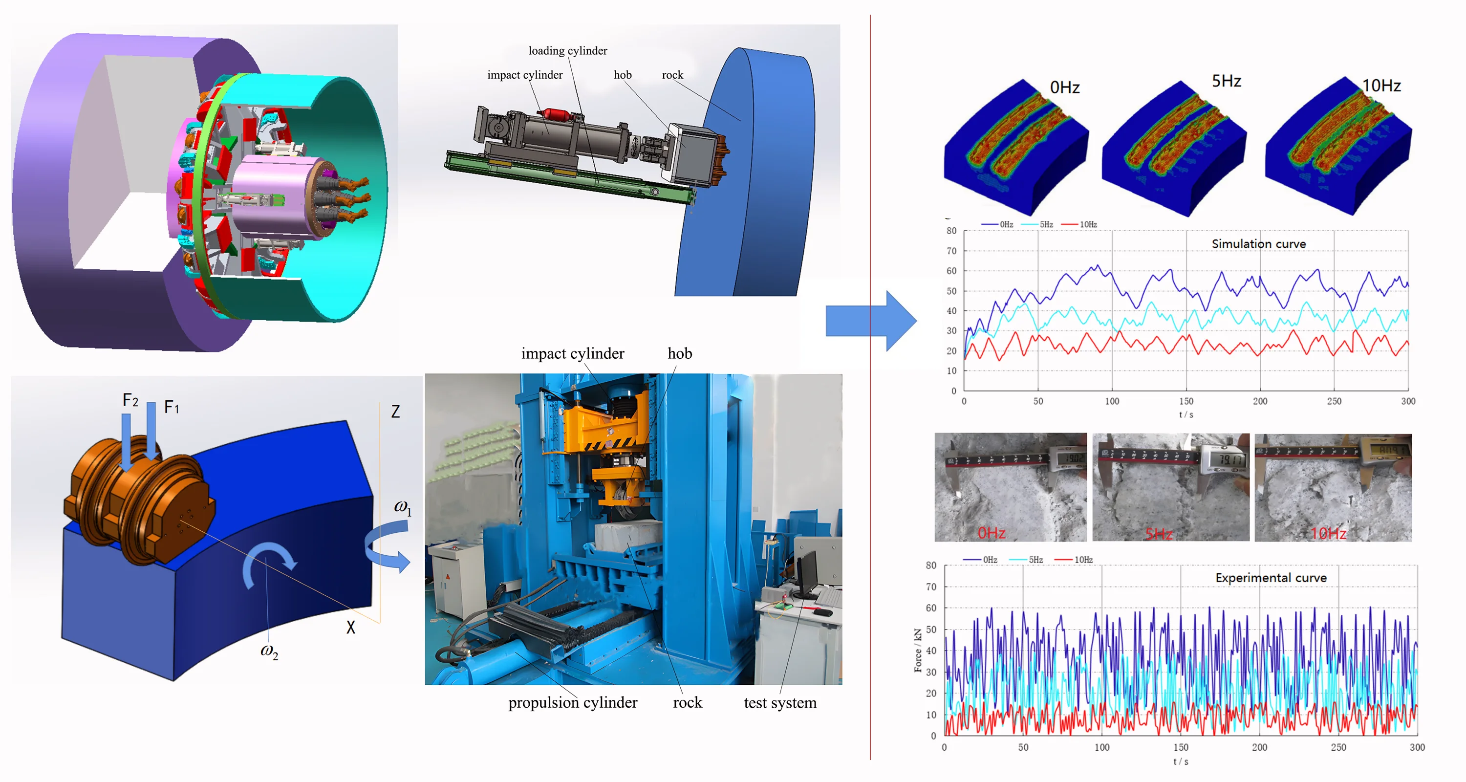
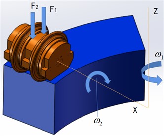
Fig. 1 shows a tunneling diagram of the impact rolling composite cutter head, which is mainly composed of rock, composite cutter head, impact cutter assembly and cutter head drive motor. Ordinary hob and impact hob are arranged on the composite cutter head. The cutter head drive motor provides rotational power to the entire cutterhead. The layout of the impact hob assembly is shown in Fig. 2.
Fig. 1Tunneling diagram of impact rolling composite cutter head: 1 – rock; 2 – composite cutter head; 3 – impact hob assembly; 4 – drive motor
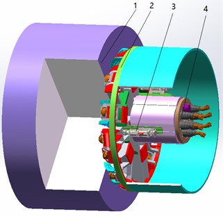
Fig. 2Multi-impact hob layout drawing: 1 – hob; 2 – impact cylinder; 3 – support ring; 4 – loading support frame
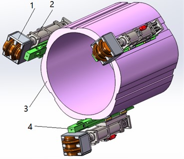
Fig. 2 shows the layout of the impact hob, which is mainly composed of a hob, an impact cylinder, a loading support frame and a support ring. During operation, the drive motor drives the support ring to rotate, and the support ring drives the impact hob assembly to rotate and break the rock. The head of the impact oil cylinder is connected with the hob, and the hob can both rotate under the action of the support ring, and break the rock under the action of the impact oil cylinder.
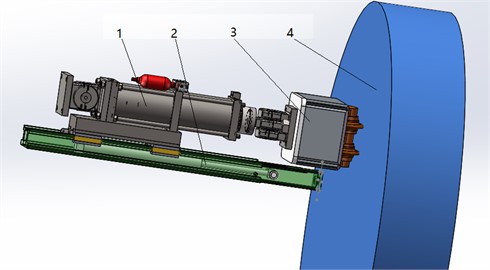
Fig. 3 contains a diagram of single-impact hob excavation process, which is mainly composed of an impact cylinder, a loading cylinder, a hob and a rock sample. During the composite rock breaking operation, the loading cylinder in the loading support frame drives the impact cylinder to move, so that the hob contacts the rock. When the loading cylinder is loaded to a certain extent, the loading is stopped and the pressure is maintained at an equal level, and the impact cylinder starts to drive the hob to impact and break the rock.
Fig. 3Structure diagram of single impact hob: 1 – impact cylinder; 2 – loading cylinder; 3 – hob; 4 – rock
2.2. Impact hob load analysis
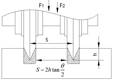
Fig. 4 contains an impact hob structural diagram, where is the cutter spacing, is the blade angle, is the hob depth, is the force of the loading cylinder, and is the force of the impact cylinder:
where is the impact vibration displacement; is the amplitude of the impact vibration; is the angular frequency, , is the impact vibration frequency; is the initial phase; then the speed of the impact hob vibration is:
Fig. 4Structural diagram of impact hob
When the hob impacts and cuts the rock, the relative speed between the hob and the rock on the cutter head is the combination of the feed speed of the cutter head, the vertical vibration speed of the hob and the rotation speed of the support ring:
The impact contact time of the hob with a rock in one vibration cycle is , and its impact force on the rock in one vibration cycle is:
It can be seen from Eq. (4) that the impact force of the impact hob acting on the rock is not a constant value, and its magnitude and direction change periodically with time, which is related to the impact amplitude and frequency of the impact hob.
Fig. 5Schematic diagram of interaction between impact hob and rock sample
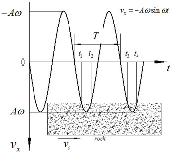
Fig. 5 contains a schematic diagram of the contact periodicity between the impact hob and the rock sample. It can be seen from Fig. 5 that, when the hob impacts and breaks the rock, the hob and the rock are periodically contacted and separated, and the characteristic function is used to characterize this state of the hob:
where is the impact time of the impact cylinder, and are the moments when the hob starts to impact the rock and starts to separate, and is the moment when the next cycle starts to impact. The characteristic function satisfies the Dirichlet convergence condition, and the characteristic function is expanded according to the Fourier series, as follows:
Then its average value in a shock period is:
A discontinuous high-frequency periodic impulse function can be equivalently decomposed into the superposition of infinite number of triangular continuous series by expanding the Fourier transforms of characteristic functions and taking the mean value in one impulse period. This mathematical transformation is of great significance for solving the rock breaking problem when the impact rolling is applied.
2.3. Hob cutting load analysis
The vertical thrust of the disc hob is composed of two parts, namely the loading force of the loading cylinder and the impact force of the impact cylinder. Its function is to break the rock below the hob and between two adjacent knives. It can be determined by the formula:
where is the diameter of the disc hob, is the hob cutting depth, is the uniaxial compressive strength of the rock, is the shear strength of the rock, is the cutter spacing, and is the blade angle.
The rolling force is determined by multiplying the vertical thrust by the constant , which is called the cutting coefficient:
When the hob impacts and rolls the rock, its cutter and the rock are contacted and separated at a certain frequency, and finally the tool cutting force has undergone an essential change with time as described below. During the impact vibration, the normal cutting force of the hob can be approximately expressed as:
According to Eq. (6), the average effective normal cutting force of the hob in one impact cycle can be obtained as:
Due to the effect of shock and vibration, the periodic contact between the tool and the rock makes the average effective tool force to reduce greatly in one shock and vibration cycle, which is only the of the ordinary tool cutting force. The change of the normal force has a significant effect on the cutting mode of the shield cutter.
Similarly, during vibration cutting, the average effective rolling force of the tool in one impact cycle is:
2.4. Optimal rock breaking volume analysis
The critical load for the initiation of radial cracks in hard and brittle materials is:
where is a coefficient related to the geometry of the hob, is the fracture toughness of the rock material, and is the Vickers hardness of the material.
Under the action of the hob, the criterion for rock material failure can be expressed by the following formula:
The cutting depth of common hob is:
The criterion formula for the failure of rock material under the action of the impact hob is:
The cutting depth of the impact hob is:
It can be seen from Eqs. (18) that the rock-breaking depth of the impact hob is deeper than that of the ordinary hob.
3. Simulation analysis
When the hob impacts and cuts the rock, the mechanical rock properties will change compared with the static state. Selecting an appropriate dynamic constitutive model of the rock is the premise of the numerical simulation of rock-breaking by impact-rolling. In this paper, the Drucker-Prager model is used in the Abaqus software for Rock-breaking hob analysis. In the Abaqus software, the linear function expression of the extended linear D-P model is as follows:
where is the deviatoric stress, is the friction angle of the material, is the equivalent compressive stress, is the cohesive force of the material, is the Mises equivalent stress, is the ratio of the triaxial tensile strength to the triaxial compressive strength, is the third invariant of deviatoric stress. The test rock is granite, and its physical and mechanical parameters are: the bulk density is 2640kg⋅m-3, the compressive strength is 168.6 MPa, the elastic modulus is 7.2×10⁴ MPa, the linear speed of the hob is 2 m/s. The rotational angular velocity and the self-rotating angular velocity of the hob can be calculated from the following equations:
In the formula, 0.835 m is the installation radius of the hob, and 0.215 m is the radius of the hob. The simulation model of impact hobbing is shown in Fig. 6. During the simulation test, the loading force parameters on the hob are: 5 kN, 10 kN and 20 kN respectively. The shock frequencies on the hob are: 0 Hz, 5 Hz and 10 Hz. Fig. 6 is the rock breaking model of the impact hob, is the force of the loading cylinder, and is the force of the impact cylinder.
Fig. 6Rock breaking model of impact hob
a) Hob loading model
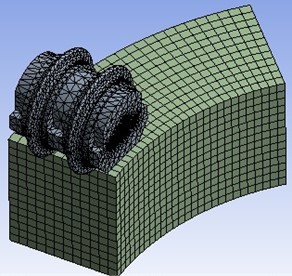
b) Model meshing diagram
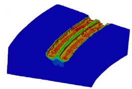
Fig. 7Fragmentation of simulated rock samples under different impact frequencies
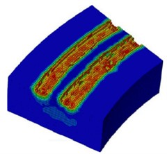
a) 0 Hz
b) 5 Hz
c) 10 Hz
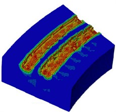
Fig. 8Fragmentation of simulated rock samples under different impact loads
a) 5 kN
b) 10 kN
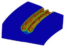
c) 20 kN
Fig. 7 contains a diagram of a rock sample fragmented under different impact frequencies, the loading force at this time is 10 kN. The value of the impact frequency is 0 Hz, 5 Hz and 10 Hz respectively, the value of the loading force is 10 kN, and the spacing between the hob cutters is about 80 mm. It can be seen from Fig. 8 that with the increase of the impact frequency, after the hob acts on the rock sample, the fractured area of the rock sample gradually increases. After the hob cutting, the rock ridge between the two hobs gradually decreases with the increase of the impact frequency. When the impact frequency is 10 Hz, the rock sample between the two hobs is almost completely broken, and there is no rock ridge area.
Fig. 8 contains a diagram of a rock sample fragmented under different impact loads. the impact frequency at this time is 5 Hz. The values of the loading force are 5 kN, 10 kN and 20 kN respectively, and the distance between the hob cutters is about 60 mm. It can be seen from Fig. 8 that with the increase of the loading force, the broken area after the hob acts on the rock sample gradually increases. With the increase of the loading force, the rock ridge between the two hobs gradually decreases. When the loading force is 20 kN, the rock sample between the two hobs is almost completely broken, and there is no rock ridge area.
4. Experiment analysis
The impact rolling and cutting test system is shown in Fig. 9, which shows the following main components: loading cylinder, impact cylinder, hob, rock sample, propulsion cylinder, testing device and hydraulic power source. During the test, the loading cylinder pushes the rotating cutterhead to move, and when the hob contacts the rock, it continues to be loaded to the required loading force . Then the impact cylinder works, and the hydraulic control system can control the impact cylinder to work with different impact frequencies. When the impact oil cylinder steadily impacts the rock sample at a certain frequency, the propelling cylinder moves to push the rock sample to move at a certain speed, so as to realize the hobbing and cutting operation for the rock sample. The load sensor is installed at the head of the loading cylinder and the propulsion cylinder to detect the output force of the cylinder in real time. The model of the load sensor is CLF-H3B. The test rock is granite, and its physical and mechanical parameters are: the bulk density is 2658kg⋅m-3, the compressive strength is 168.6 MPa, the elastic modulus is 7.2×10⁴ MPa, the moving speed of the propulsion cylinder is 0.5 m/min. The impact frequencies of the impact cylinder are 0 Hz, 5 Hz and 10 Hz. When the impact frequency changes, the loading force is kept at 10 kN. The loads used in the disturbance load test are 5 kN, 10 kN and 20 kN. When the disturbance load changes, the disturbance frequency is kept at 5 Hz. The impact rolling and cutting test results are shown in Figs. 11-14.
Fig. 9 and Fig. 10 are respectively the shield test bench and supporting pump station of the State Key Laboratory of High Performance Complex Manufacturing of Central South University. Fig. 11 and Fig. 12 are rock samples after rolling cutting test using the above shield test bench. The photographers are Dr. Guangtian Tian of Central South University and Lei Lou of Nanjing Vocational University of Industrial Technology. Dr. Lou has conducted research in this laboratory. Professor Wanrong Wu, one of the authors of this paper, is Lou’s doctoral supervisor at Central South University.
Fig. 9Impact rolling test system
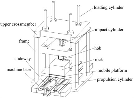
a) Three-dimensional sketch map
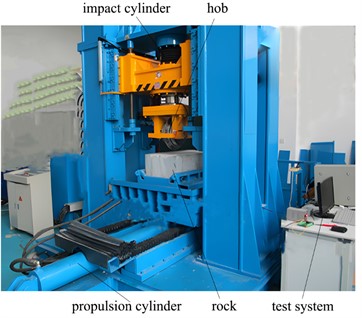
b) Physical appearance
Fig. 10Hydraulic power system
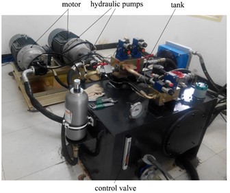
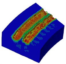
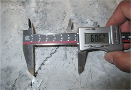
Fig. 11Fragmentation status of test rock samples under different impact frequencies
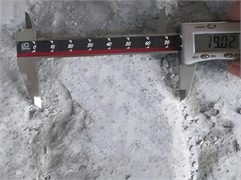
a) 0 Hz
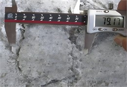
b) 5 Hz
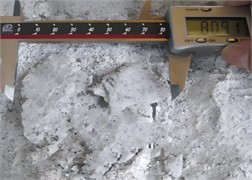
c) 10 Hz
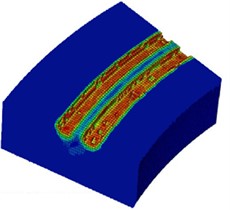
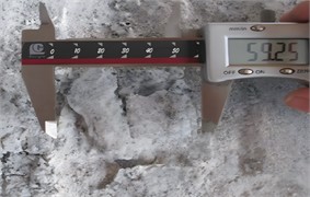
Fig. 12Fragmentation status of test rock samples under different impact loads

a) 5 kN
b) 10 kN
c) 20 kN
Fig. 11 depicts the broken state of test rock samples under different shock disturbance frequencies. The shock disturbance frequencies in Figs. 11(a), (b), and (c) are 0 Hz, 5 Hz, and 10 Hz, respectively. During the test, when the impact disturbance frequency changes, the loading force is fixed at 10 kN, and the hob spacing is about 80 mm. It can be seen from Fig. 11 that with the increase of the impact frequency, the crushing damage area of the hob on the rock sample gradually increases. After the hob cutting, the rock ridge between the two hobs gradually decreased. When the impact frequency is 10 Hz, the rock sample between the hob is almost completely broken without forming a rock ridge area.
Fig. 12 depicts fracture images of the test rock sample under different impact disturbance loads. The shock disturbance loads in Figs. 12(a), (b), and (c) are 5 kN, 10 kN, and 20 kN, respectively. During the test, when the impact disturbance load changes, the disturbance frequency is fixed at 5 Hz, and the hob spacing is about 60 mm. It can be seen from Fig. 12 that with the increase of the impact disturbance load, the rock sample area crushed by the hob gradually increases. With the increase of the disturbance load, the rock ridge between the two reels gradually decreases after every hob cut. When the disturbance load is 20 kN, the rock sample between the reels is almost completely broken, and there is no rock ridge area.
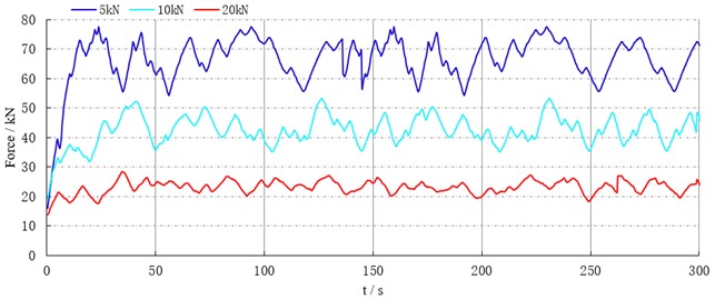
Fig. 13Comparison between simulation and experimental results of cutting force under different impact frequencies
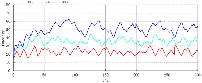
a) Simulation curve
b) Experimental curve
Fig. 13 shows the simulation and experimental curves of the hob shear force under the action of different impact disturbance frequencies. Fig. 13(a) shows the simulation curves under different shock disturbance frequencies. It can be seen from this figure that when the disturbance frequency influences the average cutting force as follows: when it is 0 Hz, then that is about 50 kN, when – 5 Hz, then about 35 kN, when 10 Hz, then about 24 kN. Fig. 13(b) depicts the test curve under different shock disturbance frequencies. It also depicts the following dependencies between the disturbance frequency and the average cutting force of the hob: 0 Hz-36 kN, 5 Hz-20 kN, and 10 Hz-8 kN. It can be seen from Fig. 13 that with the increase of the impact disturbance frequency, the hob shear force decreases significantly. Moreover, the crack density of the rock around the hob also increases, which makes it easier to break the rock.
Comparing a) and b) in Fig. 13, it can be seen that under the same disturbance frequency, the simulated value is larger than the experimental value, and the error is about 32 %. This is because there is an error between the crack density used in the simulation and the crack density generated by the actual impact disturbance.
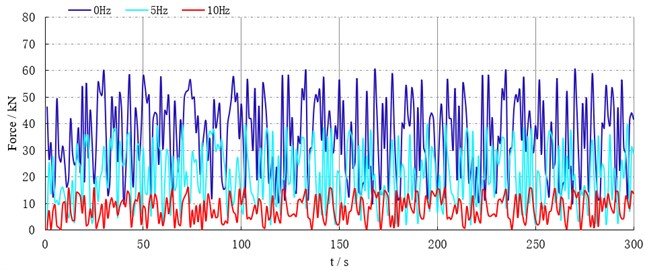
Fig. 14 shows the simulation and experimental curves of the hob shear force under different impact disturbance loads. Fig. 14(a) shows the simulation curves under different shock disturbance loads. It can be seen from the figure that the disturbance load and the average cutting force of the hob are interrelated as follows: when the first is 5 kN, then the second is about 65 kN. When the disturbance load is 10 kN and 20 kN, then the average cutting force of the hob is about 43 kN and 22 kN respectively. Fig. 14(b) shows the test curves under different shock disturbance loads. It can be seen from the figure that when the disturbance load is 5 kN, 10 kN, and 20 kN, the average chip force of the hob is about 50 kN, 23 kN and 12 kN respectively. This shows that with the increase of the impact disturbance load, the crack density of the rock around the hob increases, which makes it easier to break the rock. It can be seen from Fig. 14 that with the increase of the impact disturbance load, the cutting force of the hob is significantly reduced.
Fig. 14Comparison between simulation and experimental results of cutting force under different impact loads
a) Simulation curve
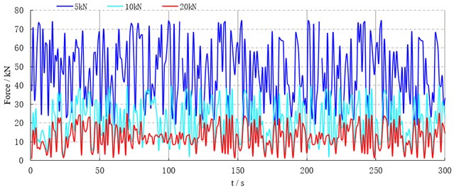
b) Experimental curve
Comparing a) and b) in Fig. 14, it can be seen that the simulation value is larger than the experimental value, and the error is about 38 %, This is caused by an error between the crack density used in the simulation and the crack density induced by the actual impact. In the impact rock breaking test, due to the existence of micro cracks and other defects inside the rock, under the action of impact load, the micro cracks and defects inside the rock expand and extend rapidly, resulting in the weakening of rock strength, so the experimental value is small. In the simulation test, the tiny cracks and defects inside the rock are not considered, resulting in large simulation results.
5. Conclusions
Aiming at solving the problems of serious tool wear and low boring efficiency when the tunnel boring machine is working in hard rock, this paper proposes a composite rock breaking method by impact cutting. The cutting force characteristics of the hob under different impact loads are analyzed, and the rock crushing characteristics under different impact disturbance loads are studied. The crushing characteristics of rock samples under different shock frequencies and shock loads are simulated and analyzed. The results show that under certain conditions, the crushed volume of rock samples increases with the increase of disturbance frequency and disturbance load.
A test bench for an impact test of cutting composite rock breaking was built, and the rock sample breaking characteristics and hob cutting force under different disturbance frequencies and disturbance loads were tested and verified. The results show that the crushed volume of the rock sample increases with the increase of the impact frequency and the impact load, and the increase of the impact frequency and the impact load is conducive to the generation of cracks in the rock sample, so that the rock sample is more easily broken. When the impact load remains unchanged, when the impact frequency is increased from 0 to 10 Hz, the rock breaking load is reduced by about 75 %, and the rock breaking volume is increased by about three times. When the impact frequency remains unchanged, when the impact load increases from 5 kN to 20 kN, the rock breaking load decreases by about 85 %.
The test results show that in order to improve the boring efficiency of hard rock tunnels, an impact hob should be added to the excavation cutter head. The impact frequency of the impact hob is 5-10 Hz, and the impact load is 10-20 kN. Limited by the test bench (The control valve used in this test is the DLHZO series servo proportional valve of Atos, whose maximum frequency is 25 Hz. Due to the large diameter of the servo cylinder, the designed frequency of the test system is 15 Hz. Considering the structural strength of the test bench and related safety requirements, the maximum frequency is set as 10 Hz during the test. This test bench is not suitable for vibration test above 15 Hz.), this paper only studies the impact frequency within 10 Hz, and further research is needed on the rock-breaking characteristics of higher impact frequencies. The test results of this paper provide a certain scientific basis for the efficient excavation of hard rock tunnels and the engineering design of hard rock tunnel boring machines.
References
-
Q. Geng, “Analytical research on the wear mechanism of TBM disc cutters based on an energy approach,” Journal of Mechanical Engineering, Vol. 54, No. 1, p. 36, 2018, https://doi.org/10.3901/jme.2018.01.036
-
Z. H. Xu, W. Y. Wang, P. Lin, L. C. Nie, J. Wu, and Z. M. Li, “Hard-rock TBM jamming subject to adverse geological conditions: Influencing factor, hazard mode and a case study of Gaoligongshan Tunnel,” Tunnelling and Underground Space Technology, Vol. 108, p. 103683, Feb. 2021, https://doi.org/10.1016/j.tust.2020.103683
-
S. Goodarzi, J. Hassanpour, S. Yagiz, and J. Rostami, “Predicting TBM performance in soft sedimentary rocks, case study of Zagros mountains water tunnel projects,” Tunnelling and Underground Space Technology, Vol. 109, p. 103705, Mar. 2021, https://doi.org/10.1016/j.tust.2020.103705
-
Y.-M. Xia, L.-K. Lin, D. Wu, L.-H. Jia, Z. Chen, and Z.-K. Bian, “Geological adaptability matching design of disc cutter using multicriteria decision making approaches,” Journal of Central South University, Vol. 25, No. 4, pp. 843–854, Apr. 2018, https://doi.org/10.1007/s11771-018-3788-6
-
M. Yang, Y.-M. Xia, L.-K. Lin, S. Qiao, and Z.-Y. Ji, “Optimal design for buckets layout based on muck removal analysis of TBM cutterhead,” Journal of Central South University, Vol. 27, No. 6, pp. 1729–1741, Jun. 2020, https://doi.org/10.1007/s11771-020-4403-1
-
E. Farrokh, “Uniformly distributed lace design for hard rock TBMs,” Tunnelling and Underground Space Technology, Vol. 110, p. 103829, Apr. 2021, https://doi.org/10.1016/j.tust.2021.103829
-
L. K. Lin, J. C. Guo, Y. M. Xia, and Y. Wu, “Layout optimization of TBM gauge disc cutters,” Modern Tunneling Technology, Vol. 53, No. 4, p. 90, 2016.
-
L. Lin, “Rock-breaking characteristics of TBM gage disc cutters and sensitivity analysis of their influencing factors,” Journal of Mechanical Engineering, Vol. 54, No. 1, p. 18, 2018, https://doi.org/10.3901/jme.2018.01.018
-
J. Q. Liu, X. B. Jia, W. Guo, and J. L. Qiao, “Research on TBM Cutter-Head Geological Matching and Failure Based on Crack Initiation,” Journal of Tianjin University (Science and Technology), Vol. 50, No. 11, pp. 1148–1153, 2017, https://doi.org/10.11784/tdxbz201701006
-
L. Lou, M.-J. Chen, W.-Y. Qin, W.-R. Wu, and H.-Y. Rui, “Research on the synchronization and shock characteristics of an air adjustment mechanism for cluster-type DTH hammers under partial loads,” Shock and Vibration, Vol. 2022, pp. 1–17, Mar. 2022, https://doi.org/10.1155/2022/9794391
-
L. H. Jia, Y. Shang, W. M. Long, Y. M. Xia, and G. J. Xue, “Effect of alloy composition of materials for TBM cutter rings on microstructure and wear resistance,” Journal of Central South University (Science and Technology), Vol. 51, No. 10, pp. 2730–2738, 2020, https://doi.org/10.11817/j.issn.1672-7207.2020.10.005
-
Y.-P. Shi, Y.-M. Xia, Q. Tan, Y.-C. Zhang, and S. Qiao, “Distribution of contact loads in crushed zone between tunnel boring machine disc cutter and rock,” Journal of Central South University, Vol. 26, No. 9, pp. 2393–2403, Sep. 2019, https://doi.org/10.1007/s11771-019-4182-8
-
Y. L. Cheng, J. Zhong, Y. B. Mei, and Y. M. Xia, “Rock fragmentation under different installation polar angles of TBM disc cutters,” Journal of Central South University, Vol. 24, pp. 2306–2313, 2017.
-
Y. L. Cheng, J. Zhong, Z. Y. Ji, and Y. B. Mei, “Geological adaptive design method and application of TBM cutterhead,” Journal of Mechanical Engineering, Vol. 54, No. 1, pp. 1–9, 2018.
-
P. Cao, Q. B. Lin, K. H. Li, and D. Y. Han, “Effects of joint angle and joint space on rock fragmentation efficiency by two TBM disc cutters,” Journal of Central South University (Science and Technology), Vol. 48, No. 5, pp. 1293–1299, 2017, https://doi.org/10.11817/j.issn.1672-7207.2017.05.023
-
Y.-M. Xia, T. Ouyang, X.-M. Zhang, and D.-Z. Luo, “Mechanical model of breaking rock and force characteristic of disc cutter,” Journal of Central South University, Vol. 19, No. 7, pp. 1846–1852, Jul. 2012, https://doi.org/10.1007/s11771-012-1218-8
-
L. J. Du, S. S. Ji, L. F. Zuo, H. X. Kong, J. L. Xu, and Y. L. Du, “Wear and consumption of large diameter disc cutters for hard rock TBM under giant porphyritic granite,” Journal of China Coal Society, Vol. 40, No. 12, pp. 2974–2978, 2015.
-
Q. M. Gong et al., “Influence of different cutter spacings on rock fragmentation efficiency of Beishan granite by TBM,” Chinese Journal of Geotechnical Engineering, Vol. 37, No. 1, pp. 54–60, 2015, https://doi.org/10.11779/cjge201501005
-
H. Ma, L. Yin, and H. Ji, “Numerical study of the effect of confining stress on rock fragmentation by TBM cutters,” International Journal of Rock Mechanics and Mining Sciences, Vol. 48, No. 6, pp. 1021–1033, Sep. 2011, https://doi.org/10.1016/j.ijrmms.2011.05.002
-
T. Moon and J. Oh, “A study of optimal rock-cutting conditions for hard rock TBM using the discrete element method,” Rock Mechanics and Rock Engineering, Vol. 45, No. 5, pp. 837–849, Sep. 2011, https://doi.org/10.1007/s00603-011-0180-3
-
H. Bejari and J. Khademi Hamidi, “Simultaneous effects of joint spacing and orientation on TBM cutting efficiency in jointed rock masses,” Rock Mechanics and Rock Engineering, Vol. 46, No. 4, pp. 897–907, Jul. 2013, https://doi.org/10.1007/s00603-012-0314-2
-
R. Hasanpour, J. Schmitt, Y. Ozcelik, and J. Rostami, “Examining the effect of adverse geological conditions on jamming of a single shielded TBM in Uluabat tunnel using numerical modeling,” Journal of Rock Mechanics and Geotechnical Engineering, Vol. 9, No. 6, pp. 1112–1122, Dec. 2017, https://doi.org/10.1016/j.jrmge.2017.05.010
-
A. Manouchehrian and M. Cai, “Analysis of rockburst in tunnels subjected to static and dynamic loads,” Journal of Rock Mechanics and Geotechnical Engineering, Vol. 9, No. 6, pp. 1031–1040, Dec. 2017, https://doi.org/10.1016/j.jrmge.2017.07.001
-
X. B. Li, J. R. Yao, and K. Du, “Preliminary study for induced fracture and non-explosive continuous mining in high-geo-stress hard rock mine – a case study of Kaiyang phosphate mine,” Chinese Journal of Rock Mechanics and Engineering, Vol. 32, No. 6, pp. 1101–1111, 2013.
-
C. Chen, X. B. Li, and F. Feng, “Numerical study on damage zones of the induced roadway surrounding rock,” Gold Science and Technology, Vol. 26, No. 6, pp. 771–779, 2018.
About this article

This research was supported by the National Nature Science Foundation of China (Grant No. 51774340), Natural Science Research Project of Jiangsu Province Colleges and Universities (20KJB560034) and Innovation (Qinglan) Project of Jiangsu Province.
The datasets generated during and/or analyzed during the current study are available from the corresponding author on reasonable request.
The authors declare that they have no conflict of interest.
