Abstract
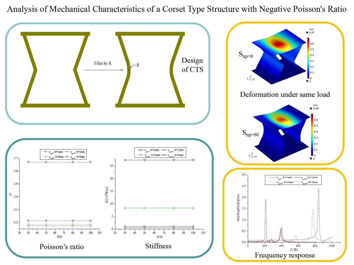
For mechanical metamaterials and their vibration isolation ability, a new corset type structure (CTS) is designed from the inward hexagonal steel structure by applying fillet at the inward corners. Ten CTS cells are born by using the different fillet radius. The fillet radius is 10 mm to 100 mm, but the cell mass remains constant when the plate has the same thickness. The static deformation, vibration modality and harmonic response of these NPR structures are analyzed in this paper. These CTS cells are modeled by using the finite element method (FEM) with a uniform grids. In static analysis, a surface load and a point load on the top plate are respectively considered to study the elastic deformation, the NPR and the stiffness of CTS cells with different fillet radii and thicknesses. These CTS cells have a greater NPR and a higher stiffness than the original inward hexagonal steel structure. In modal analysis, the natural frequency, the eigenmode and the fixed modality are numerically computed. These frequency values and displacement distributions of CTS cells show that these CTS cells have a higher vibration frequency than the origin inward hexagonal structure cell. In harmonic response analysis, the frequency domain is from 1 Hz to 1000 Hz, and the excitation force is on the top surface of the upper plate. All displacement responses of these CTS cells are analyzed. The harmonic response analysis result shows that the resonance magnitude can be significantly suppressed by these new CTS cells. The analysis result presents the characteristics of this new CTS, and it is beneficial for the vibration isolation in engineering application.
Highlights
- A new corset type structure (CTS) is designed from the inward hexagonal steel structure by applying fillet at the inward corners. The CTS can be easily obtained though CAD.
- CTS has larger Poisson's ratio and stiffness than the original structure. CTS is more suitable for engineering load-bearing structures.
- CTS has lower resonance response value, and is more conducive to isolation of large low-frequency vibrations.
- The characteristics of CTS varies with the fillet radius. With the increase of radius, the negative Poisson’s ratio and stiffness increase at the same time.
1. Introduction
Offshore structures often have to withstand relatively heavy loads when moving machinery or when exposed to wind and waves. Green smart ship research requires the lighting and functionality of ship structures to meet the needs of maneuverability and ecological navigation. Technological advances in metamaterial design can address these additional needs over conventional design solutions. By altering the internal cell structure, metamaterials structures have some extraordinary physical properties that natural materials structures do not possess any one, for example, negative stiffness [1], [2], negative Poisson's ratio (NPR) [3], [4] etc. NPR material is a type of stretching material. This materials shrinks laterally when it is subjected to longitudinal compression, and expands laterally when subjected to longitudinal tension [5], [6]. Due to its special tensile expansion effect and excellent vibration absorption ability, metamaterial structures have become a hot research topic in the field of vibration isolation, anti-shock and other engineering applications. In marine application, steel structures with negative Poisson’s ratio are metamaterials available for specific functionalization of support structures [7].
In recent years, honeycomb structures with NPR have been actively researched. The geometry of each cell in honeycomb structures can affect the whole mechanical performance. Specifically, when suffering an impact load, the dynamic characteristics of honeycomb structures with NPR depend not only on impact velocity and relative density, but also on the cell’s microstructure [8]. Additionally, the concave corner honeycomb structures have the excellent energy absorption properties [9]. Considering micro cells, in addition to conventional honeycomb structures, there are also butterfly-shaped honeycomb structures [10], [11], arrow-shaped honeycomb structures [12], chiral hexagonal honeycomb structures [13], [14]. Honeycomb structures are improved by integrating concave hexagonal honeycomb cells and Miura-origami cells together [15]. These structures with NPR can have the improved buffering performance. Carbon fiber-reinforced composite structures with NPR [16], have much better impact resistance at low speeds than at high speeds. Besides that, to meet the requirement of converting positive, negative, and zero Poisson's ratios to each other, a newly-designed structure enables the macro Poisson’s ratio to be changed by varying cell structure [17]. The honeycomb sandwich panel structure [18], which combines a normal 2D hexagonal honeycomb with positive Poisson’s ratio and a 2D concave hexagonal honeycomb with NPR, has softened structure with a lowered stiffness and a significant vibration absorption ability.
The study of metamaterial structures with NPR has opened up a new research field with practical application value. Applying arbitrary Poisson’s ratio metamaterial structures to ship vibration isolation, zero Poisson's ratio materials have broad application potential in cylindrical shells exposed to high pressure [19]. Compared to the conventional base, the mass of the hexagonal structure base is reduced by 46.11 % and the average acceleration vibration level is reduced by 7.37 dB. For star structure base, the mass is reduced by 59.36 %, and the average acceleration vibration level is reduced by 5.63 dB. So the base is designed to be lightweight and enhanced in vibration isolation by utilizing metamaterials with negative Poisson's ratio [20]. In response to the anti-collision and energy absorption requirements of the front longitudinal beams of automobiles, a box structure has been innovated with an equivalent elastic modulus and stress, and the energy absorption ability of this box structure can be enhanced under in-plane loading due to negative Poisson’s ratio behaviors of this structure [21]. The NPR structure is difficult to be solved through analytical formulas, though some solving theories are suitable for solving plate and beam [22], [23], the FEM provides convenient modeling and solving technique [24]. From these presented research results, the NPR structure has significant advantages in the engineering application, especially for the vibration isolation. Because the engineering structure needs an enough stiffness to support heavy-duty machinery, and an efficient isolation ability to resist vibration excitation in a wide frequency band, so further research and development of NPR metamaterial structures is necessary, and the characteristics of cell structure with NPR should also be widely developed [25].
The purpose of this study is to investigate the mechanical characteristics of NPR structures and explore their application ability. Therefore, this paper proposes a novel corset type structure (CTS) with NPR. Based on the concave hexagonal structure, this CTS is composed of top and the bottom end plates, as well as concave supports on either sides. The angle between the side support and the end plate is 60°. CTS cells are created by adjusting the middle radius of the concave support. The static load and modal analyzes of CTS cells are performed using the finite element method. In addition, a compression verification test is performed as part of the static stiffness analysis.
2. Geometry design of CTS cells
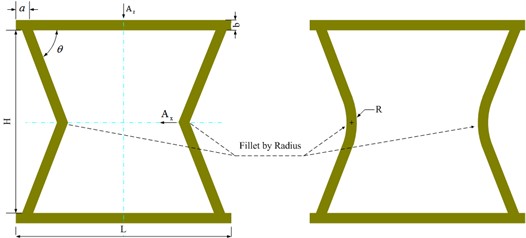
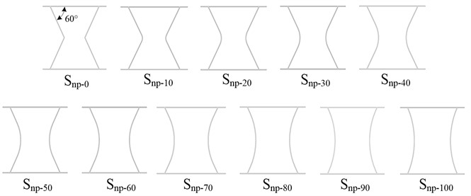
In structure mechanics, Poisson’s ratio is defined as the ratio of the absolute value of the transverse positive strain to the axial positive strain, when the structure is subjected to unidirectional tension or compression. As shown in Fig. 1, the CTS designed in this paper is a hollow steel frame. The thickness of each plate is uniformly b mm, the height between the upper and lower end plates is 100 mm, and the length of these end plates is 130 mm. The distance from supporting point to side edge is 15 mm. The normal depth of the structure cell is equal to mm. The contact angle between the side and the end plates is 60°. A typical feature of side plates is a fillet of radius in the center. When the value of is 0 mm, the corset type structure becomes an inward hexagonal structure. Ten types of CTS cells and their original inward hexagonal structure cell are shown in Fig. 2, and the CTS cell becomes thicker with the increase of radius . To simplify the description, Snp-i is used to describe the CTS cell rounded by a value of mm ( mm, 0 ~ 100), and during the design process, these values of are 10 mm, 20 mm, 30 mm, 40 mm, 50 mm, 60 mm, 70 mm, 80 mm, 90 mm, and 100 mm. Three types of plate thicknesses, 1 mm, 2 mm and 3 mm, are used in this analysis. When 1 mm, the mass of these structure cells is 397.74 g. When 2 mm, the mass of these structure cells is 771.36 g. When 3 mm, the mass of these structure cells is 1156.74 g. With constant thickness values, these structure cells have the same weight.
As shown in Fig. 1, a CTS cell can be created by rounding the inward hexagonal cell at the corners with a radius , and the mechanical properties of the CTS cell can be changed by the fillet.
Assuming the top plate is rigid, when the top plate is compressed, there is a uniform displacement of the top plate. The side inclined plates act with the lever movement in the inward hexagonal cell, but the side fillet plates in the CTS cell act with the movement of a buckling beam.
Fig. 1Generation of CTS cell
For the inward hexagonal cell:
where, is displacement in vertical direction, is displacement in horizontal direction. So, Poisson’s ratio can be expressed as:
Fig. 2Fillet change of CTS cells
In CTS cells, the static motion of a buckling beam under an axial load is expressed as [26]:
where, is the flexural rigidity, is the axial rigidity, is the length of the buckled beam, m is the mass per unit length, is the axial load. The transverse deformation can be caused by the axial force .
Under mechanical movement, NPR of CTS cell Snp-0 is calculated by using Eq. (2). With the interaction of transverse and axial motions, NPR of CTS cell Snp-I ( 0) is not easy to calculated by using Eq. (3). This problem can be solved by a numerical method. In this paper, the CTS cell is modeled by using the finite element method (FEM), and the numerical model is computed in the software COMSOL. Displacements and of the CTS cells are analyzed simultaneously.
3. Numerical preparation of CTS cells
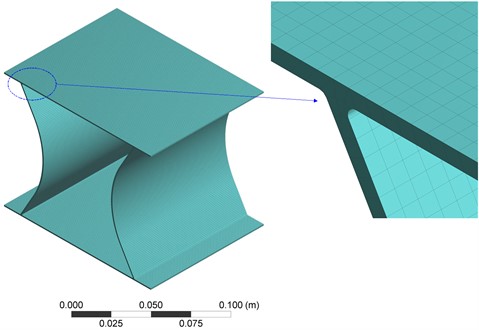
As foundation supports, CTS cells are expected to be capable of supporting specific loads, particularly surface and point loads. These material properties of steel include Young’s modulus 2.0×10¹¹ Pa, Poisson’s ratio 0.3, density 7850 kg/m3. To perform numerical analysis of CTS cells, they are modeled by using the finite element method. Grids distribution of Snp-60 is shown in Fig. 3, and there are 50700 elements and 350187 nodes under a mesh size of 1 mm. The uniformity of these grids allows for accurate modeling of CTS cells, and the connection corner can have a moderate shape. These grids are utilized for surface load analysis, point load analysis, modality analysis and frequency response analysis.
Fig. 3Grids of CTS Snp-60
In order to perform the static analysis of CTS cells, a uniform compression force is applied on the upper surface of the top plate. The force is varied at 30 N, 50 N, 80 N, and 100 N respectively. Similarly, for point load analysis, a force of 100 N is applied at the top center of the upper plate. The modal analysis of several CTS cells is conducted, including natural and fixed modalities. A harmonic response is also done to compare the difference between CTS cells.
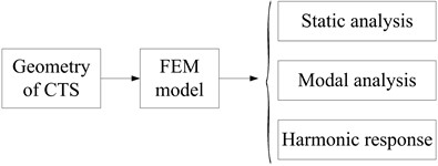
Fig. 4The flow chart of numerical analysis
4. Numerical results and discussions
According to the flow chart shown in Fig. 4, the geometry of CTS is drew in the solidworks software, and the geometry file with iges format is imported into the numerical workplace, after modeled by using the FEM, three analyses are conducted as follows.
4.1. Discussion of static mechanics
Based the values of and , the Poisson’s ratio and stiffness k of CTS cells are analyzed according to the numerical data. It shows the changes of the Poisson’s ratio of CTS cell Snp-0 and Snp-60 in Fig. 5, and it indicates that the Poisson’s ratio values of CTS cells remain constant with load. However, the CTS cell Snp-60 has a lower negative Poisson’s ratio compared to the original inward hexagonal structure cell Snp-0. Specifically, when 1 mm, the relative percentage of NPR is 28.65 %. As the plate thickness increases, the NPR of CTS cell Snp-60 increases by 0.40 % at 2 mm, and 1.42 % at 3 mm.
Table 1Mechanical parameters of CTS cells under compression at 100 N
(mm) | (10-2mm) | (10-2mm) | (106N/m) | ||
Snp-0 | 1 | 21.18 | 18.32 | –1.73 | 0.47 |
Snp-10 | 19.33 | 16.84 | –1.74 | 0.52 | |
Snp-20 | 17.24 | 15.32 | –1.78 | 0.58 | |
Snp-30 | 15.16 | 13.97 | –1.84 | 0.66 | |
Snp-40 | 13.13 | 12.72 | –1.94 | 0.76 | |
Snp-50 | 11.18 | 11.53 | –2.06 | 0.89 | |
Snp-60 | 9.34 | 10.39 | –2.23 | 1.07 | |
Snp-70 | 7.60 | 9.27 | –2.44 | 1.31 | |
Snp-80 | 6.06 | 8.22 | –2.71 | 1.65 | |
Snp-90 | 4.69 | 7.13 | –3.04 | 2.13 | |
Snp-100 | 3.52 | 6.02 | –3.42 | 2.84 | |
Snp-0 | 2 | 2.69 | 2.33 | –1.73 | 3.71 |
Snp-10 | 2.46 | 2.14 | –1.74 | 4.07 | |
Snp-20 | 2.20 | 1.95 | –1.78 | 4.55 | |
Snp-30 | 1.94 | 1.78 | –1.84 | 5.17 | |
Snp-40 | 1.68 | 1.62 | –1.93 | 5.95 | |
Snp-50 | 1.43 | 1.47 | –2.06 | 6.98 | |
Snp-60 | 1.20 | 1.46 | –2.43 | 8.34 | |
Snp-70 | 0.98 | 1.19 | –2.41 | 10.17 | |
Snp-80 | 0.79 | 1.05 | –2.68 | 12.72 | |
Snp-90 | 0.61 | 0.92 | –3.00 | 16.36 | |
Snp-100 | 0.46 | 0.78 | –3.36 | 21.62 | |
Snp-0 | 3 | 0.81 | 0.70 | –1.72 | 12.35 |
Snp-10 | 0.74 | 0.64 | –1.73 | 13.53 | |
Snp-20 | 0.66 | 0.58 | –1.77 | 15.11 | |
Snp-30 | 0.59 | 0.54 | –1.83 | 17.08 | |
Snp-40 | 0.51 | 0.49 | –1.91 | 19.64 | |
Snp-50 | 0.44 | 0.44 | –2.03 | 22.98 | |
Snp-60 | 0.37 | 0.40 | –2.19 | 27.36 | |
Snp-70 | 0.30 | 0.36 | –2.39 | 33.27 | |
Snp-80 | 0.24 | 0.32 | –2.63 | 41.41 | |
Snp-90 | 0.19 | 0.28 | –2.92 | 52.80 | |
Snp-100 | 0.14 | 0.24 | –3.26 | 69.11 |
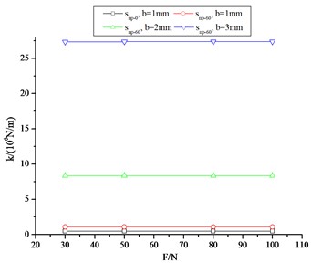
In Fig. 6, there are the changes in stiffness of CTS cell Snp-0 and Snp-60, and it is shown that the stiffness values of CTS cells also remain constant with load. It is worth noting that CTS cell Snp-60 has a higher stiffness than the original inward hexagonal structure cell Snp-0. At 1 mm, the relative percentage of stiffness ratio is 127.66 %. As the plate thickness increases, the stiffness of CTS cell Snp-60 is amplified significantly. When the plate thickness is 2 mm, the stiffness is increased by about 8 times. When 3 mm, the stiffness is amplified by 30 times.
For other types of CTS cells, the mechanical parameters are shown in Table 1. The compression force is 100 N, and the displacement and of CTS cells vary with the fillet radius. When the thickness of CTS cells has the same value, the NPR of CTS cells decreases with the increase of fillet radius, but the stiffness of CTS cells increases with the fillet radius. So all CTS cells Snp-i (0) exhibit a greater NPR and a higher stiffness than the original CTS Snp-0.
Fig. 5Poisson’s ratio of CTS cells
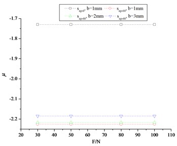
Fig. 6Stiffness of CTS cells
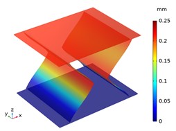
For further comparison of static analysis, the deformation distributions of CTS cell Snp-0 and Snp-60 under surface compression are shown in Fig. 7. It is observed that under the compression of 100 N, the Snp-0 cell shrinks in the -direction and the -direction, whereas the Snp-60 cell also shrinks in the same way, but with a smaller displacement value. Besides that, the Snp-60 cell has a larger -directional displacement compared to its -directional displacement. So the Snp-60 cell has a larger stiffness and a lower NPR than the Snp-0 cell.
Fig. 7The displacement distribution of CTS cells under compression 100 N
a) Snp-0, 1 mm
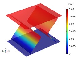
b) Snp-0, 2 mm
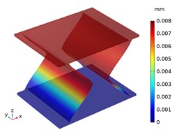
c) Snp-0, 3 mm
a) Snp-60, 1 mm
a) Snp-60, 2 mm
a) Snp-60, 3 mm
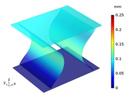
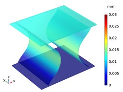
Beside with the compression deformation, the tension deformations of CTS cell Snp-0 and Snp-60 are shown in Fig. 8. With the bottom of zero displacement, CTS cell Snp-0 and Snp-60 have extension in the -direction and in the -direction. Significantly, the -directional deformation is greater than -directional deformation in each CTS cell, especially in the CTS cell Snp-60.
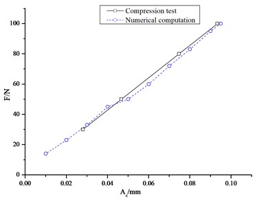
To verify numerical computation, a numerical compression analysis is conducted using the CMT6103 electronic universal testing machine. The CTS cell Snp-60 is clamped between two joints, as illustrated in Fig. 9, and the amplitude range of the compression force is set at 0-100 N. The load-displacement curves are shown in Fig. 10. The stiffness values show that the stiffness of CTS cell Snp-60 remains constant under compression. The difference ratio between the numerical calculation and test analysis is less than 4.67 %.
Fig. 8The displacement distribution of CTS cells under tension 100 N
a) Snp-0, 1 mm
b) Snp-0, 2 mm
c) Snp-0, 3 mm
d) Snp-60, 1 mm
e) Snp-60, 2 mm
f) Snp-60, 3 mm
Fig. 9Compression test of Snp-60
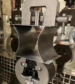
Fig. 10The load-displacement curves of Snp-60
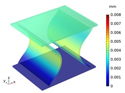
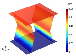
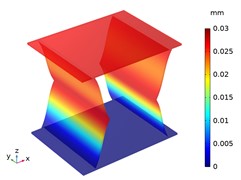
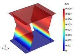
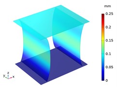
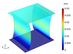
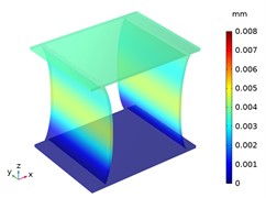
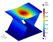
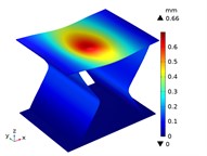
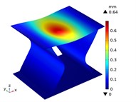
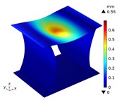
Under the centric point compression, the displacement distribution of CTS cells with 1 mm is shown in Fig. 11. The graphs indicate a concavity on the top of each CTS cell, with the maximum displacement value labeled. The largest displacement is 0.67 mm in Snp-0, and the smallest displacement is 0.55 mm in Snp-100. The displacement variation ratio is 17.91 %. The results indicate that the shrinking displacement under point force decreases significantly with an increase in fillet radius. This is due to the fact that the stiffness of CTS cell is heightened by the fillet. Fig. 12 shows the acentric point compression in CTS cell Snp-0,Snp-60 and Snp-100. The CTS cell Snp-0 has the greatest deformation with a value of 0.58 mm. The CTS cell Snp-60 has the smaller deformation with a value of 0.33 mm. The CTS cell Snp-100 has the smallest deformation with a value of 0.27 mm. The CTS cell has the greater resistance to deformation.
Fig. 11The displacement of CTS cells with b= 1 mm under centric point force 100 N
a) Snp=0
b) Snp=10
c) Snp=20
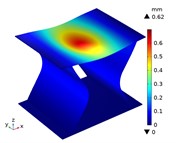
d) Snp=30

e) Snp=40
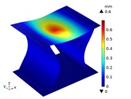
f) Snp=50
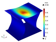
g) Snp=60
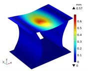
h) Snp=70

i) Snp=80

j) Snp=90
k) Snp=100
Fig. 12The displacement of CTS cells with b= 1 mm under acentric point force 100 N
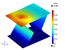
a) Snp=0
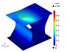
b) Snp=60
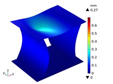
c) Snp=100
4.2. Discussion of modality
The modality of structure is its natural vibration characteristics. In this work, the natural frequency and the vibration mode of CTS cells are analyzed. Because the CTS cell is fixed on a base and connected to other solid structure at the top end in application, so the fixed modality is also studied.
In Fig. 13, it shows the first order vibration frequency of CTS cells under both free and fixed conditions. It is apparent that the frequency of each CTS cell increases as the fillet radius increases, assuming they have the same thickness and are in the same condition. When the CTS cell is fixed, its frequency can be lowered than the corresponding free one. Furthermore, the frequency of each CTS cell can be increased by increasing the plate thickness.
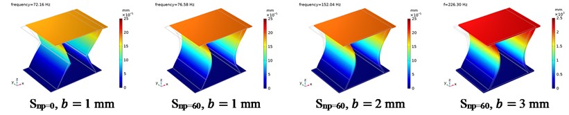
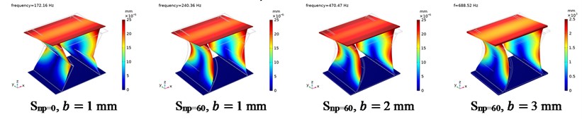
Besides, the vibration mode is crucial in determining the vibration characteristics of CTS cells. There provides examples of the free modes for Snp=0 and Snp=60 in Fig. 14. At the first order vibration mode, the side plates move inwards while the end plates curl at the middle in CTS Snp=0. Once the side plates are filleted, the round side plates and end plates move together, and the end plates curl at the middle in CTS Snp=60. Despite changes in plate thickness, the vibration modes of CTS Snp-60 remain constant. At the second order vibration mode, there are nearly identical vibration modes, with inward quasi-zero state and maximum deformation at the four corners. At the third order vibration mode, end plates have the same vibration mode with moving inwards, and side plates have the same vibration mode with moving outwards.
Fig. 13The 1st order modal frequency of CTS cells
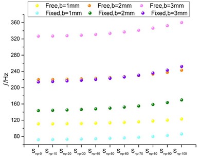
Fig. 14The free modal displacement distribution of CTS cells
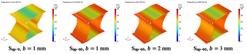
a) The 1st order
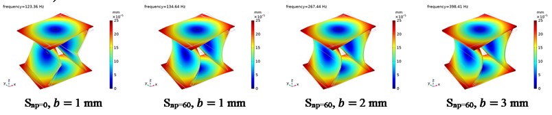
b) The 2nd order
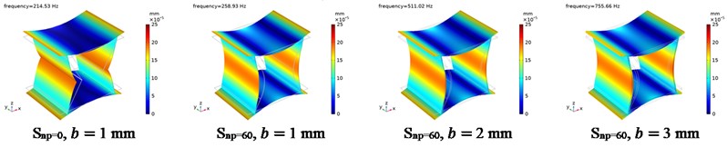
c) The 3rd order
The fixed modes of Snp=0 and Snp=60 are shown in Fig. 15, where the bottom end plate has the zero displacement, and the top end plate moves in together with side plates due to the fixed condition. At the first order vibration mode, the plates move in the -direction. At the second order vibration mode, the plates rotate along the -axis. Whereas, at the third order vibration mode, the plates rotate along the -axis.
4.3. Discussion of harmonic responses
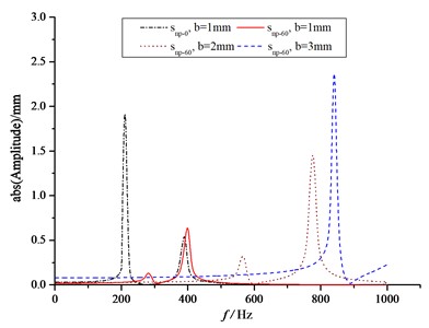
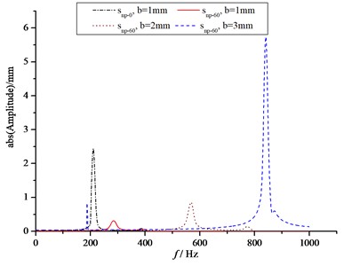
To analyze the vibration response of engineering structures under loads that vary sinusoidally over time, the harmonic response analysis is conducted for CTS cells Snp=0 and Snp=60. These CTS cells are excited at the top end plate with a surface force of 10 N. In conventional ship and vehicle environments, the frequency of concern is typically below 1000 Hz. Therefore, the responses of at center point of upper plate () and at center point of side plate () are calculated within the range of 1 Hz to 1000 Hz. So when the displacement of these CTS cells are obtained, the sustained dynamic characteristics of CTS cells, as well as the resonance effect, can be analyzed.
Fig. 15The fixed modal displacement distribution of CTS cells
a) The 1st order
b) The 2nd order

c) The 3rd order
Fig. 16The frequency response curves of CTS cells
a)
b)
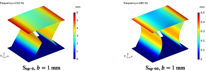
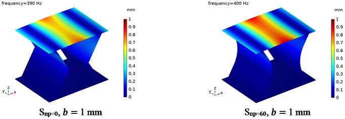
In Fig. 16, it shows the absolute value of harmonic responses of and . In Fig. 16(a), it is observed that for the CTS cell Snp=0 with 1 mm, the first resonance vibration occurs at approximately 210 Hz with a displacement value of 2.78 mm, while the second resonance vibration occurs at approximately 390 Hz with a displacement value of 0.67 mm. In the case of CTS cell Snp=60 with 1 mm, the first resonance vibration occurs at approximately 280 Hz with a displacement value of 0.15 mm, and the second resonance vibration occurs at approximately 400 Hz with a displacement value of 0.77 mm. The results indicate that the first resonance vibration frequency can be increased, and the first resonance magnitude can be significantly reduced by 94.60 %. The second resonance vibration frequency is slightly increased, but the second resonance magnitude is enlarged by 14.93 %. Moreover, both the resonance frequency and magnitude increase with plate thickness for CTS cell Snp-60. As shown in Fig. 16(b), the harmonic response is significantly affected by the inclined plate and fillet plate. In the case of CTS cell Snp=0 with 1 mm, the first resonance vibration is observed at approximately 210 Hz with a displacement value of 3.54 mm, while the second resonance vibration occurs at about 390 Hz with a displacement value of 0.10 mm. In the case of CTS cell Snp=60 with 1 mm, the first resonance vibration occurs at about 280 Hz with a displacement value of 0.33 mm, while the second resonance vibration occurs at approximately 400 Hz with a displacement value of 0.05 mm. It is evidently shown that the resonance vibration frequency has a similar trend with the response analysis. The first resonance magnitude can be significantly suppressed by 90.68 %, and the second resonance magnitude can also be suppressed by 50.00 %. In the case of CTS cell Snp=60 with 3 mm, the first resonance vibration frequency of the side fillet plate shifts to a lower value of 188 Hz with a magnitude of 1.22 mm.
Fig. 17 shows the displacement distributions for CTS cells Snp=0 and Snp=60 with 1 mm, as excited in resonance vibration. It is indicated that for the first resonance vibration, the vibration modes of CTS cells Snp=0 and Snp=60 are identical. The top end plate has a large displacement at both ends and a small displacement at the center, while both side plates move inwards with a moderate displacement. In the case of the second resonance vibration, the vibration mode of CTS cells remains consistent. The top end plate has a large displacement at the center and a small displacement at both ends, while the side plate exhibits almost zero displacement.
Fig. 17The resonance displacement distribution of CTS cells
a) The first resonance vibration
b) The second resonance vibration
5. Conclusions
For metamaterial structures, this paper presents a new type of CTS cells with NPR. The CTS cell is designed from an inward hexagonal structure by filleting the inclined side plates. The static behavior, vibration modality and harmonic response of CTS cells were numerically computed by using the FEM. The characteristic parameters were analyzed, and a compression test of CTS cell Snp-60 was conducted to verify the numerical static analysis. In general, some conclusions were get from this study.
The increase of fillet radius can promote an increase of the NPR and the stiffness of CTS cells. When compared to the original Snp-0 with an inclined plate, the CTS cell Snp-100 with a fillet radius of 100 mm has the NPR value of -3.42 with an increase of 97.69 %. This increase in NPR was achieved while maintaining the same mass. With the identical condition, the stiffness of CTS cell Snp-100 is 2.84×10⁶ N/m, which is 504.26 % higher than the original Snp0, as the stiffness of the original Snp-0 is only 0.47×10⁶ N/m.
The vibration frequency of CTS cells is also increased with the fillet radium, but the displacement distribution of every mode remains almost identical.
The resonance frequency and corresponding magnitude of the harmonic response indicate that CTS cell can suppress the first order vibration amplitude, and increase the first order vibration frequency. Compared with CTS cell Snp-60, the resonance amplitude of CTS cell Snp-0 is reduced by 90.68 %, and the first resonance frequency is increased by 33.33 %.
According to these characteristics of CTS cells, the CTS structures are very suitable for vibration isolation in different engineering applications.
References
-
C. Findeisen, J. Hohe, M. Kadic, and P. Gumbsch, “Characteristics of mechanical metamaterials based on buckling elements,” Journal of the Mechanics and Physics of Solids, Vol. 102, pp. 151–164, May 2017, https://doi.org/10.1016/j.jmps.2017.02.011
-
T. A. M. Hewage, K. L. Alderson, A. Alderson, and F. Scarpa, “Double‐negative mechanical metamaterials displaying simultaneous negative stiffness and negative Poisson’s ratio properties,” Advanced Materials, Vol. 28, No. 46, pp. 10116–10116, Dec. 2016, https://doi.org/10.1002/adma.201605935
-
J. Yu, “State-of-art of metamaterials with negative Poisson’s ratio,” (in Chinese), Journal of Mechanical Engineering, Vol. 54, No. 13, pp. 1–14, 2018, https://doi.org/10.3901/jme.2018.13.001
-
J.-W. Jiang, S. Y. Kim, and H. S. Park, “Auxetic nanomaterials: recent progress and future development,” Applied Physics Reviews, Vol. 3, No. 4, p. 04110, Dec. 2016, https://doi.org/10.1063/1.4964479
-
H. Chen and F. Li, “Design, simulation and experimental verification of novel 3D metamaterial structures with negative Poisson’s ratio,” Mechanics of Advanced Materials and Structures, Vol. 30, No. 1, pp. 17–28, Jan. 2023, https://doi.org/10.1080/15376494.2021.2006839
-
K. E. Evans, M. A. Nkansah, I. J. Hutchinson, and S. C. Rogers, “Molecular network design,” Nature, Vol. 353, No. 6340, pp. 124–124, Sep. 1991, https://doi.org/10.1038/353124a0
-
H. Qin and D. Yang, “Vibration reduction design method of metamaterials with negative Poisson’s ratio,” Journal of Materials Science, Vol. 54, No. 22, pp. 14038–14054, Nov. 2019, https://doi.org/10.1007/s10853-019-03903-z
-
H. L. Han, X. C. Zhang, and P. Wang, “Dynamic responses and energy absorption properties of honeycombs with negative Poisson’s ratio,” (in Chinese), Explosion and Shock Waves, Vol. 39, No. 1, pp. 47–57, 2019.
-
X. H. Hou and G. S. Yin, “Dynamic crushing performance analysis for auxetic honeycomb structure,” Journal of Mechanical Strength, Vol. 38, No. 5, pp. 905–910, 2016, https://doi.org/10.16579/j.issn.1001.9669.2016.05.001
-
H. T. Guan, R. L. Tian, and Z. W. Zhang, “Study of the vibrational characteristics of butterfly-shaped honeycomb sandwich panel,” (in Chinese), Journal of Harbin Engineering University, Vol. 43, No. 9, pp. 1383–1390, 2022.
-
P. Li, J. X. Yue, X. B. Li, and S. Peng, “Impact resistance of thickness-graded arrow-shaped honeycomb pedestals with negative Poisson’s ratio,” (in Chinese), Explosion and Shock Waves, Vol. 40, No. 7, pp. 27–37, 2020, https://doi.org/10.11883/bzycj-2019-0414
-
J. X. Qiao and C. Q. Chen, “Impact resistance of uniform and functionally graded auxetic double arrowhead honeycombs,” International Journal of Impact Engineering, Vol. 83, pp. 47–58, Sep. 2015, https://doi.org/10.1016/j.ijimpeng.2015.04.005
-
Q. Zhi, D. Li, H. Sun, and W. Zhu, “Adjustment of multi-directional elastic properties of chiral metamaterial via a 3D printing-based soft-hard bi-material strategy,” Composite Structures, Vol. 307, p. 116646, Mar. 2023, https://doi.org/10.1016/j.compstruct.2022.116646
-
X. C. Zhang, X. Y. Zhu, and N. Li, “A study of the dynamic response characteristics of hexagonal chiral honeycombs,” (in Chinese), Journal of Vibration and Shock, Vol. 35, No. 8, pp. 1–7, 2016, https://doi.org/10.13465/j.cnki.jvs.2016.08.001
-
R. J. Ma, Y. T. Wang, M. Li, J. Feng, and J. G. Cai, “Research on in-plane buffer performance of honeycomb material based on Miura pattern,” (in Chinese), Manned Spaceflight, Vol. 26, No. 1, pp. 48–55, 2020.
-
C. F. Zhao, H. W. Zhu, J. Ren, and J. L. Zhong, “Impact mechanics of composite materials with negative Poisson’s ration structure,” (in Chinese), Journal of Qingdao University of Science and Technology (Natural Science Edition), Vol. 42, No. 5, pp. 75–80, 2021.
-
S. Chen, B. Wang, and S. W. Zhu, “New strategy for interconversion of positive, negative, and zero Poisson’s ratios,” (in Chinese), Journal of Harbin Engineering University, Vol. 43, No. 9, pp. 1306–1313, 2022.
-
Y. Hou, R. Neville, F. Scarpa, C. Remillat, B. Gu, and M. Ruzzene, “Graded conventional-auxetic Kirigami sandwich structures: flatwise compression and edgewise loading,” Composites Part B: Engineering, Vol. 59, pp. 33–42, Mar. 2014, https://doi.org/10.1016/j.compositesb.2013.10.084
-
S. Zhong, H. X. Qin, and D. Q. Yang, “Metamaterial design with arbitrary Poisson’s ratio in the specified topological ground structure,” (in Chinese), Journal of Wuhan University of Technology, Vol. 40, No. 12, pp. 21–30, 2018.
-
B. H. Wu, X. W. Zhang, and D. Q. Yang, “Real ship application analysis of vibration isolation base made by auxetic metamaterials,” (in Chinese), Ship Engineering, Vol. 40, No. 2, pp. 56–62, 2018.
-
W. Zhang, W. B. Hou, and P. Hu, “Mechanical properties of new negative Poisson’s ratio crush box with cellular structure in plateau stage,” Acta Materiae Compositae Sinica, Vol. 32, No. 2, pp. 534–541, 2015, https://doi.org/10.13801/j.cnki.fhclxb.20140616.003
-
S. P. Parida and P. C. Jena, “Selective layer-by-layer fillering and its effect on the dynamic response of laminated composite plates using higher-order theory,” Journal of Vibration and Control, 2022.
-
P. C. Jena, D. R. Parhi, and G. Pohit, “Dynamic investigation of FRP cracked beam using neural network technique,” Journal of Vibration Engineering and Technologies, Vol. 7, No. 6, pp. 647–661, Dec. 2019, https://doi.org/10.1007/s42417-019-00158-5
-
S. P. Parida and P. C. Jena, “Design and finite element analysis of thick walled laminated composite pressure vessel,” International Journal of Innovative Technology and Exploring Engineering, Vol. 8, No. 10, pp. 4389–4394, Aug. 2019, https://doi.org/10.35940/ijitee.j9831.0881019
-
Y. K. Gao, “Auxetic metamaterials and structures,” Journal of Materials Engineering, Vol. 49, No. 5, pp. 38–47, 2021, https://doi.org/10.11868/j.issn.1001-4381.2019.000391
-
W. Lestari and S. Hanagud, “Nonlinear vibration of buckled beams: some exact solutions,” International Journal of Solids and Structures, Vol. 38, No. 26-27, pp. 4741–4757, Jun. 2001, https://doi.org/10.1016/s0020-7683(00)00300-0
About this article

This paper and some analysis are under the funding of General Projects of Liaoning Provincial Department of Education (L2015066), and the assistance of Dalian Maritime University Education Reform Project and Fujian Province Key Laboratory of Ship and Ocean Engineering.
The datasets generated during and/or analyzed during the current study are available from the corresponding author on reasonable request.
Yuchao Song: conceptualization, investigation, writing-review and editing. Yanxin Yang: data curation, investigation. Changkuan Chi: data curation. Guobin Li: visualization. Jiahui Zhang: software. Zhaowen Zhang: data curation.
The authors declare that they have no conflict of interest.
