Abstract
To analyze the mechanical performance of the arc end tooth connection structure, the optimization of electronic sensors based on the connection structure of double rotors with circular arc end teeth was studied. By designing and optimizing the structural dimensions of the arc end tooth, the relative position of the grinding wheel and the workpiece was determined, and the optimal electromagnetic actuator size, as well as the number and installation position of the optimized sensors, were obtained. The experimental results showed that the relative error of the rigid vibration mode of the arc end tooth double rotor connection structure was controlled within 10 %. At high speeds, the electromagnetic actuator had a significant control effect on the vibration of the centrifugal machine shaft. It diminished the vibration amplitudes in the and directions by 37.6 % and 30.2 %, respectively. By optimizing the double rotor connection structure with circular end teeth and electronic sensors, effective control of the relative error of rigid vibration modes has been achieved, leading to significant reduction of the centrifugal shaft's vibration at high speeds. In addition, the sensor layout was optimized to enable real-time equipment vibration monitoring, ensuring equipment safety and stability. These achievements not only enhance the mechanical performance of the rotor system, but also provide important guarantees for the stability of the mechanical system.
1. Introduction
The circular arc end tooth double rotor connection structure is a commonly used mechanical transmission structure, which has high transmission efficiency and load-bearing capacity [1]. In practical applications, there are still some problems with this structure, such as vibration and noise. Therefore, it is of great theoretical and practical significance to optimize the connection structure of circular arc end teeth double rotors in order to improve their operational performance and reliability [2]. Electromagnetic actuators, as an important actuator, are widely used in mechanical systems. It has the characteristics of small size, light weight, fast response speed, and can achieve precise position and force control [3]. However, electromagnetic actuators also face some challenges in practical applications, such as thermal effects, nonlinear characteristics, etc. In addition, the placement of sensors plays a crucial role in the monitoring and control of mechanical systems [4]. Reasonably arranging sensors can obtain real-time operational status and working parameters of mechanical systems, providing accurate feedback information for system control and adjustment [5]. Therefore, this study presents a methodology for optimizing the dual rotor connection structure with circular arc end teeth and electronic sensors to achieve reliable and effective operation. By reasonable layout and optimization of electronic sensors, real-time monitoring and control of the dual rotor connection structure can reduce the risk of faults and improve the operational efficiency of the equipment. Furthermore, a thorough investigation was carried out to assess the transmission efficiency of the dual rotor connection design featuring circular end teeth. Comparative experiments and simulation studies were conducted to validate the efficacy of the optimization approach. This study has achieved an efficient and stable operation of the connecting structure, thereby providing strong support for practical engineering applications. The research is divided into four parts. The first part is a summary of relevant research. The second part is based on the optimization design of the circular arc end tooth double rotor connection structure and electronic sensors. The third part is an experimental analysis based on the circular arc end tooth double rotor connection structure and electronic sensor optimization. The fourth part is a summary of the research. This study focuses on optimizing the design of the double rotor connection structure with circular end teeth and electronic sensors. The novelty of this study lies in determining the best size of the electromagnetic actuator and the optimized sensor number and installation position. This is achieved by optimizing the structural dimensions of the circular end teeth and the relative position of the double rotors. It effectively controls the relative error of the rigid vibration mode and significantly reduces the vibration of the centrifugal shaft at high speeds. Secondly, by properly arranging sensors, the real-time monitoring of equipment vibration has been achieved, thereby ensuring the safety and stability of the equipment.
2. Related works
Gear transmission is a common mechanical transmission method that transmits torque and motion through the engagement and rotation of gears. Tang et al. designed and analyzed the double arc tooth profile, and designed and processed four sets of harmonic transmission devices. The test results indicated that the control of double arc tooth profile parameters could effectively improve comprehensive performance. Moreover, different parameters are needed for different application scenarios. This conclusion is supported by previous research [6]. The Meng team proposed a kinematic geometric lubrication theory for linear conjugate gear transmission and studied the global lubrication characteristics of gear transmission. They detected the lubrication weak area of the entire meshing zone and worked out the optimal operating parameters. It was found that there was a lubrication weak point path on the tooth surface, which accounted for approximately 33 % of the entire meshing area [7]. The Liu team proposed an axial circular arc tooth profile cylindrical worm drive, whose worm was cut by a turning tool. They also developed a meshing theory for this type of worm drive. The results indicated that the meshing quality of the worm drive was good, and the number of worm threads should not exceed four [8]. Ma et al. established a three-dimensional model and studied its contact characteristics to reconstruct the tooth surface of circular arc tooth profile cylindrical gears. The results indicated that the design parameters had an impact on the contact ellipse, and the contact area of the ellipse gradually increased from the tooth root to the tooth top [9]. The Syzrantsev team established a mathematical model for the formation process of the arc tooth surface of a semi rolling cylindrical gear. They also created an algorithm and program for computing the coordinates of the arc tooth meshing active line. The results indicated that in the case of errors in the relative positions of gears and hubs, the geometric characteristics of arc tooth meshing could help calculate its load-bearing capacity and durability [10].
Electronic sensors are devices or devices that can convert physical quantities into electrical signals, enabling the detection and measurement of various physical quantities in the environment. The Hi research team proposed the design of a sleeve type torque sensor and established a relationship model between torque and voltage based on mechanical theory. The test results showed that a drill pipe torque sensor can be used to measure torque, thus addressing the issue of drill pipe sticking [11]. Wang et al. proposed a fault observer based on resource allocation network neural network prediction for mechanical system fault detection, which utilized a prediction function to predict the sampled values of sensors. Experiments have shown that the stability of the observer error system could reach 90 % [12]. Electromagnetic actuator is a device that utilizes the principle of electromagnetic force to generate mechanical motion. It typically comprises of electromagnetic coils, magnets, and mechanical components. Vashisht et al. utilized pattern search optimization technology to optimize the parameters of electromagnetic actuators. They conducted a comparison of this method with the optimal loop shaping robust controller and the optimal traditional proportional differential controller. The results showed that the electromagnetic actuator proposed by the research institute saved 168 % of control energy [13]. Wang et al. proposed a multi-objective optimization strategy based on genetic algorithm to optimize the static thrust of the actuator and conducted experimental analysis of its dynamic performance. The results showed that the average static thrust of the optimized actuator’s working stroke increased by 21.8 %. The cutoff frequencies of the thrust response increased by 129.1 %, 79.6 %, and 74.3 %, respectively [14].
In summary, many researchers have conducted research and design on gear transmission, sensors, and electromagnetic actuators. However, the applicability of these methods needs to be improved, and there is still a lack of strong evidence for analyzing the structure of circular end teeth. Therefore, the study aims to optimize the design of the double rotor connection structure with circular end teeth and electronic sensors, with the aim of improving the mechanical performance of the circular end tooth double rotor connection structure.
3. Optimization design of electronic sensors based on the connection structure of double rotors with Arc end teeth
This chapter concentrates on optimizing the design of the circular arc end-tooth double rotor connection structure. It optimizes the structural parameters of the electromagnetic actuator and the sensor installation on the test bench. This optimization provides trustworthy fundamental data for subsequent experiments.
3.1. Design of connection structure between Arc end teeth and double rotors
The circular arc end tooth structure is a common mechanical connection structure, characterized by the use of circular arc shaped gear roots and grooves to connect the contact surface, rather than traditional straight tooth roots and grooves. This structure can provide a larger contact area and a more uniform stress distribution, thereby improving the strength and reliability of the connection. The circular end tooth structure is widely used in various mechanical systems, such as transmission devices, connecting devices, robotic arms, etc. [15]. The purpose of the design of the circular end tooth double rotor connection structure is to adapt to the installation position of the test bench and the installation space limitations of the circular end tooth rotor, and to prepare for the study of the connection damping and stiffness of the circular end tooth connected rotor under complex loads of tension compression torsion bending. By designing appropriate connection structures, the stability and reliability of the rotor connection under complex loads can be ensured, providing reliable basic data for subsequent research. The structure of the circular end teeth is shown in Fig. 1.
Fig. 1Structure of Arc end teeth
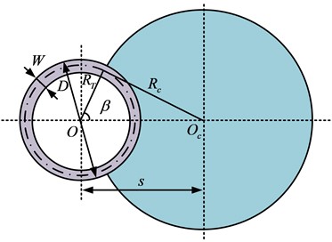
a) Layout
b) Tooth shape
The contact surface between concave and convex teeth is the key to completing the torque transmission of circular arc end teeth. The torque is determined based on the actual situation, and the relationship between the outer diameter of the end teeth and the torque is shown in Eq. (1):
where, the transmitted torque is and the outer diameter of the arc end tooth is . The inner diameter should be greater than or equal to 75 % of the outer diameter. The calculation of tooth width is shown in Eq. (2):
where, the width of the end teeth is . After determining the basic parameters of the end teeth, the modulus can be determined, and the modulus calculation is shown in Eq. (3):
where, the diameter pitch is , the modulus is , and the number of teeth is . The calculation of other tooth shape parameters is shown in Eq. (4):
where, the tooth tip clearance is , and its height is . The tooth top height is , the tooth root height is , the full tooth height is , the end tooth pitch diameter is , and the corresponding working condition calculation parameters are , , and . The calculation of the transition arc radius is shown in Eq. (5):
where, the radius of the transition arc is , and the pressure angle of the end teeth is . The expression for calculating the cross tooth angle is shown in Eq. (6):
where, the cross tooth angle is , the number of grinding wheel spans is . The calculation for the radius of the grinding wheel and the distance between the grinding wheel centerline and the center line axis of the circular end tooth blank is shown in Eq. (7):
where, the radius of the grinding wheel is , and the spacing between the center lines and axes of the circular end tooth blank is . The parameter design of the formed grinding wheel needs to consider the main parameters, geometric shape design, working grinding surface design, and nonworking surface design of the grinding wheel to ensure the required arc end tooth shape is processed. When designing grinding wheels, it is necessary to reasonably select the top width to ensure that the required tooth groove shape can be machined. The calculation of the top width of the grinding wheel is shown in Eq. (8):
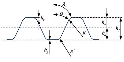
where, the top width of the grinding wheel is and the grinding width of the grinding wheel pitch plane is . The corresponding width sum on both sides is . The three-dimensional diagram of the end tooth model is shown in Fig. 2.
Fig. 23D View of end tooth model
a) 1/30
b) Whole
The tooth groove widths of both convex and concave teeth are equal, and the width at the top of the grinding wheel used to machine these teeth is also identical [16]. The mechanical model for the centering of circular end teeth used in the study belongs to a model based on the principle of elastic averaging. The principle of this model is that under the pre-tightening force of the central pull rod, the positioning features of the concave and convex teeth begin to cooperate with each other. With an increase in pre-tightening force, the elastic deformation of the connection surface occurs, reducing the relative error difference between the positioning features. This results in a higher positioning accuracy of the connection surface. This model can be used to describe the centering performance of arc end teeth, that is, under the action of preload, the positioning features of arc end teeth can match each other and maintain high-precision positioning.
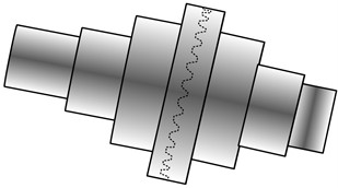
Fig. 3Double rotor structure diagram
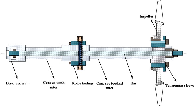
The double rotor structure is a mechanical structure composed of concave tooth rotors, convex tooth rotors, pull rods, impellers, and other auxiliary components [17]. The concave tooth rotor and convex tooth rotor are the core components of the double rotor structure, which transmit power through gears that mesh with each other. The pull rod serves to connect the concave tooth rotor and the convex tooth rotor, allowing them to rotate simultaneously. The impeller is an important component of a double rotor structure, which generates airflow or liquid flow through rotation, used to transfer energy or achieve fluid transportation. The auxiliary components mainly provide axial positioning function for the rotor to ensure stable operation of the rotor. These auxiliary components can include bearings, shaft sleeves, seals, etc. [18]. The design and assembly of a double rotor structure can achieve efficient energy transfer and fluid transportation, and is widely used in various mechanical equipment and industrial fields. The double rotor structure diagram is shown in Fig. 3.
3.2. Optimization design of electromagnetic actuators
The circular arc end tooth and double rotor connection structure is a commonly used connection method for electromagnetic actuators [19]. The electromagnetic actuator is connected to the double rotor through arc end teeth, allowing for the connection and transmission between the electromagnetic actuator and the mechanical system [20]. The study focuses on the design and optimization of a 12 pole E-type electromagnetic actuator. The objective of optimizing electronic actuators is to maximize the electromagnetic force in the actuator and achieve the optimal solution. To achieve this goal, it is necessary to optimize the design parameters of electromagnetic bearings. The magnitude of electromagnetic force is positively correlated with the increase of magnetic pole area and slot area. However, the fixed size of the electromagnetic actuator causes an increase in the magnetic pole area to result in a decrease in the slot area. Therefore, it is necessary to find the optimal relationship between the two in order to maximize electromagnetic force. The first optimization objective is to consider selecting an appropriate cross-sectional area and slot area ratio when determining the electromagnetic force, to achieve the minimum volume of the stator silicon steel sheet. The first objective optimization function is shown in Eq. (9):
where, the magnetic pole area is , the slot area is , and the volume of the stator silicon steel sheet is . The first constraint is shown in Eq. (10):
where, the determined value of electromagnetic force is . The magnetic field strength is . The gap between the stator and rotor is . The relative permeability of air is . The slot filling rate is . The coil current density is . The second optimization condition is to determine the volume of the silicon steel sheet of the stator and adjust the proportion of the area to maximize the electromagnetic force of the electromagnetic actuator. The second optimization objective function is shown in Eq. (11):
where, the maximum electromagnetic force is . The constraint conditions for the second optimization objective are shown in Eq. (12):
where, the volume of the stator silicon steel sheet is . The two optimization methods can be summarized as obtaining the maximum electromagnetic force when the volume of the stator silicon steel sheet is the smallest. When the diameter of the stator is known, parameters such as magnetic pole height can be calculated. The calculation of the stator diameter is shown in Eq. (13):
where, the diameter of the stator is , which refers to the sum of the inner diameter of the stator and the thickness of the stator yoke. The magnetic pole height is , and the outer diameter of the stator is calculated as shown in Eq. (14):
where, the outer diameter of the stator is , which refers to the sum of the stator diameter and the stator thickness. The calculation for the outer diameter of the rotor is shown in Eq. (15):
where, the outer diameter of the rotor is , which refers to the sum of the inner diameter of the rotor and the thickness of the rotor shaft diameter. The calculation of the inner diameter of the rotor is shown in Eq. (16):
where, the inner diameter of the rotor is . Through the above steps, the size parameters of the stator and rotor of the motor can be determined for the design and manufacturing of the motor. The calculation for other parameters is similar when the outer diameter of the stator and other related parameters are known. The design and processing steps of the electromagnetic actuator are shown in Fig. 4.
Fig. 4Design and processing steps of electromagnetic actuators
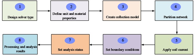
Based on the given rotor system and bearing capacity requirements, the diameter of the electromagnetic actuator shaft and the thickness of the stator can be determined. Then, these parameters are substituted into the optimization equation to obtain the initial size of the electromagnetic actuator. After the design is completed, ANSYS can be used for simulation. In ANSYS, it first establishes a parameterized geometric model and imports the basic structural parameters of the electromagnetic actuator. Through simulation, the maximum electromagnetic force of the electromagnetic actuator can be obtained and the error between it and the actual value can be calculated. Next, the structural dimensions of the electromagnetic actuator is optimized. The goal of optimization is to maximize the electromagnetic force per unit volume. During the optimization process, the outer diameter of the stator is set as a fixed value to study the influence trend of other electromagnetic actuator structural parameters on electromagnetic force. This approach allows for the design and simulation of an electromagnetic actuator that complies with specifications, and optimization to enhance electromagnetic force performance.
3.3. Arc end tooth test bench based on electronic sensor optimization
The design purpose of the arc end tooth test bench system is to study the dynamic characteristics of the arc end tooth connection interface in complex working conditions of the rotor system, and establish a multi axis complex load rotor vibration excitation testing identification test method. The end tooth connected rotor test bench enables exploration of the rotor dynamics of the rotor system under multiple axis loads. It also provides theoretical, methodological, and technical support for predicting and designing rotor stability with connection interfaces. In addition, the test bench can also consider interface mechanical parameters such as contact stiffness and damping of the engine rotor connection structure, providing support for rotor stability prediction technology [21]. The design of the end tooth connected rotor test bench is shown in Fig. 5.
Fig. 5Design of an end tooth connected rotor test bench
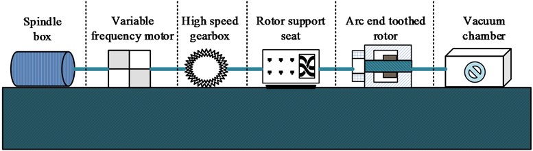
The structure of the arc end tooth test bench includes a driving source, a double output variable frequency motor, a maximum speed of 15000 r/min, and a power of 200 KW. Power transmission transfers the power from the driving source to the arc end tooth connected rotor through a gearbox. The gearbox has a speed ratio of 1:7, which can increase the working speed to over 70000 r/min. The arc end tooth connected rotor is connected to a slender shaft through a diaphragm coupling and a high-speed gearbox to achieve power transmission. An auxiliary system is designed to meet the normal operation of the test bench. Among them, the support structure of the high-speed gearbox adopts sliding bearings, with a required oil pressure of 0.2 MPa and a fuel supply flow rate of 60 L/min, and the working environment is atmospheric. The supporting structure of the double rotor system test bench adopts rolling bearings, with a required oil pressure of 0.45 MPa, a range of oil supply flow of 0-20 L/min, and a working environment of vacuum. Due to the different oil pressure, oil supply flow rate, and working environment required for sliding bearings and rolling bearings in high-speed gearboxes and test benches, it is necessary to use two ways of oil supply. Due to limited laboratory space, a single oil station is used for oil supply. A self-regulating valve is installed in a location with low oil supply pressure in the high-speed gearbox to solve the problem. Flow, pressure, and temperature transmitters are installed in the oil supply circuit to monitor the operating status of the test bench in real-time. To achieve a vacuum working environment below 200 Pa, it is necessary to start the vacuum pump before starting the equipment to vacuum.
The test bench coupling adopts a flexible connection method of flexible slender shaft, an intermediate sleeve, and diaphragm disk, which can reduce the impact on the double rotor system. During operation, the flexibility of the membrane disk can absorb the relative displacement between the rotors, making the coupling have small vibration displacement, high operating speed, and can absorb large displacement. To achieve accurate measurement of temperature displacement and other related variables in a double rotor system, the research is conducted to optimize the number and installation position of sensors. During the rotation process, it is necessary to measure the radial displacement at the position of the shaft sleeve and the radial displacement at the connection interface of the arc end teeth. Therefore, two eddy current sensors are installed at the corresponding positions to measure radial displacement in the vertical and horizontal directions. A total of six sensors are installed at the three positions. To measure the stress of the squirrel cage bearing cage bars, four eddy current sensors are installed to measure the horizontal and vertical stress of the cage bars in the squirrel cage. To measure the operating temperature of the bearings, three sensors are installed to measure the bearing temperature at each location point.
4. Experimental analysis based on the connection structure of Arc end teeth double rotors and optimization of electronic sensors
This chapter conducts experimental analysis on the double rotor connection structure with circular end teeth. Through the production and analysis of circular end teeth, as well as data testing of electromagnetic actuators and test benches, the reliability of the research method is analyzed.
4.1. Analysis of the connection structure of double rotors with Arc end teeth
S31603 was used as the material for the circular end teeth, with an ambient temperature of room temperature. The material properties and state parameters of the circular end teeth are shown in Table 1.
Table 1Material properties and Arc end tooth state parameters
Content | Parameter | Numerical value | Unit |
Property | Ambient temperature | 25 | °C |
Poisson’s ratio | 0.3 | / | |
Tensile strength | 480 | MPa | |
Density | 7.97 | G/cm3 | |
Elastic modulus | 205 | GPa | |
Arc end tooth status parameters | Torque | 75 | N.m |
Axial preload | 40000 | N | |
Speed | 20000 | r/min | |
Temperature | 25 | °C |
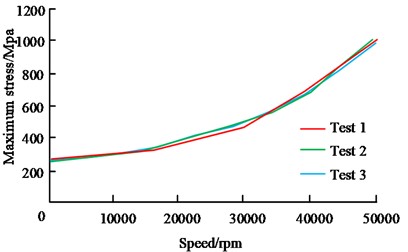
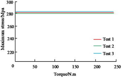
Table 1 provides the working environment temperature, Poisson's ratio, tensile strength, density, and elastic modulus of the material. The rotational parameters of the circular end teeth included torque, axial preload, rotational speed, and temperature, which would be used for the design and analysis of the circular end teeth. After the design was completed, based on finite element analysis, the relationship between the stress of the arc end teeth and relevant parameters could be obtained, as expressed in Fig. 6.
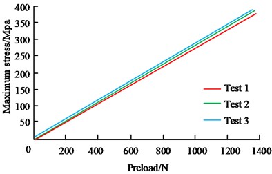
Fig. 6(a) shows the relationship between the maximum stress on the contact surface of the circular arc end teeth and the preload force. The consistent results of the three analyses show a linear relationship between the preload force and the maximum stress on the circular arc end teeth. Fig. 6(b) shows the relationship between maximum stress and rotational speed, indicating that the maximum stress value is approximately 280 MPa at zero rotational speed. When the speed is below 35000 r/min, the impact on the maximum stress is relatively small. However, beyond this speed, the maximum stress increases rapidly. Therefore, the working speed should be controlled within 35000 r/min. Fig. 6(c) shows the relationship between the maximum stress and torque in the rotor. The maximum stress is approximately 280 MPa when the torque is applied to 0, and remains at approximately 280 MPa when the torque is 250 N. m, with no significant changes within the allowable torque range. The results show that there is a linear relationship between the preload force and the maximum stress exerted on the circular end teeth, which could be linked to the impact of preload force on the contact area. At zero rotational speed, the value of maximum stress is about 280 MPa, which is because there is no effect of centrifugal force caused by rotational speed at this time. And when the rotational speed exceeds 35000 r/min, the centrifugal force makes the maximum stress increase rapidly. As for the relationship between the maximum stress and torque in the rotor, the maximum stress is about 280 MPa when the torque is applied to zero, and it is maintained at about 280 MPa when the torque is 250 N.m. It appears that the maximum stress is not considerably impacted by the torque within the allowable range of torque. The stiffness analysis results of the arc end tooth connection are shown in Fig. 7.
Fig. 6Relationship between stress of Arc end teeth and related parameters
a) Preload
b) Speed
c) Torque
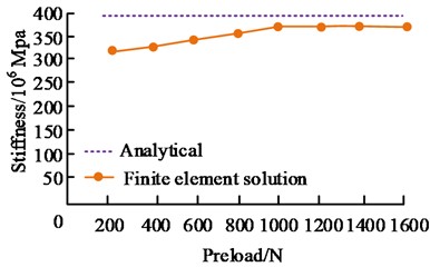
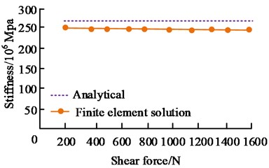
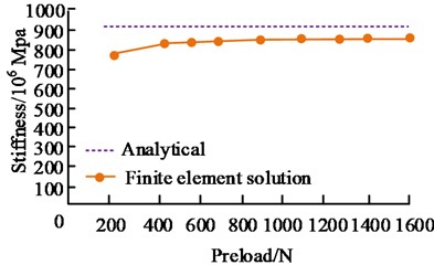
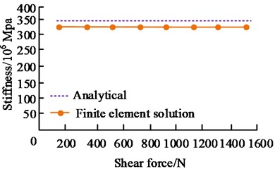
Fig. 7Analysis results of the stiffness of Arc end tooth connection
a) Axial compression stiffness
b) Shear stiffness
c) Torsional stiffness
d) Bending stiffness
In Fig. 7, in the analytical and finite element analysis solutions, the four stiffness errors of the rotor were all within 10 %. Within the allowable range of errors, the overall stiffness was obtained by multiplying the single tooth stiffness by 30. The modal test results of the end tooth double rotor connection showed that the relative error of the rigid vibration mode was controlled within 10 %, within the allowable range of error. The errors in the four stiffnesses of the rotor in both the analytical solution and the FEA solution are within 10 %, affirming the precision of both methods’ outcomes. The reason that the analytical solution is larger than the FEA solution may be due to the fact that the analytical solution is simplified and idealized during the calculation, making the results more easily comprehensible and processed. However, in some cases it may fail to fully consider all the factors, ultimately leading to overestimation.
4.2. Verification of optimization effect of electromagnetic actuators
By establishing an ANSYS parameterized geometric model and introducing the basic structural parameters of the electromagnetic actuator, the maximum electromagnetic force of the electromagnetic actuator could be obtained with an error of 0.5 %, and the structural dimensions of the electromagnetic actuator could be optimized. The optimization goal was to maximize the electromagnetic force per unit volume. The optimized size parameters of the battery actuator are shown in Table 2.
Table 2Optimized size parameters of battery actuators
Name | Numerical value | Unit |
Outer diameter of stator | 156 | mm |
Median diameter of stator | 141 | mm |
Inner diameter of stator | 76 | mm |
Outer diameter of rotor | 75 | mm |
Inner diameter of rotor | 55 | mm |
Air gap | 0.5 | mm |
Thickness of main magnetic pole | 15.5 | mm |
Thickness of secondary magnetic pole | 7.75 | mm |
Thickness of stator yoke | 7.5 | mm |
Thickness of rotor yoke | 10 | mm |
Number of turns of small pole coils | 30 | circle |
Large pole coil turns | 60 | circle |
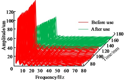
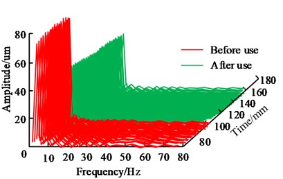
After optimizing the electromagnetic actuator, the electromagnetic force could reach 800 N, an increase of 14.4 % compared to before optimization. In a centrifuge, the stator was installed on the lower support of the centrifuge. The rotor component was fixed on the centrifugal machine shaft through a tensioning sleeve. When the electromagnetic actuator operated, the magnetic field generated by the stator interacted with the rotor, causing displacement of the rotor. To measure the deflection displacement of the shaft, eddy current sensors at 90° were usually used. This type of sensor could indirectly measure shaft displacement by measuring changes in eddy currents. By measuring the displacement of the shaft, the effectiveness of electromagnetic actuators in suppressing shaft vibration could be evaluated. The vibration control effect of the electromagnetic actuator is shown in Fig. 8.
As shown in Fig. 8, at a low speed of 400 r/min, the application of an electromagnetic actuator had a significant effect on the vibration control of the centrifugal shaft. Before applying the electromagnetic actuator, the amplitude of the -axis was 115 um, and the amplitude of the -axis was 80 um. After applying the electromagnetic actuator, the amplitude of the -axis decreased to 61 um, and the peak vibration decreased by 47 %. Similarly, the amplitude of the -axis decreased to 49 um, and the vibration value decreased by 38.7 %. At a high speed of 1800 r/min, the vibration control effects in the and directions were 37.6 % and 30.2 %, respectively. The results showed that the vibration effect of the centrifugal machine shaft was significantly improved after applying an electromagnetic actuator. The results show that the optimized electromagnetic actuator displays efficient vibration control in the centrifuge. At lower rotational speeds, utilization of the electromagnetic actuator can substantially decrease shaft amplitude, resulting in vibration control rates of 47 % and 38.7 % in the and directions. At high speeds, although the vibration control effect is slightly reduced, there is still an improvement of 37.6 % and 30.2 %. This is mainly due to the optimized dimensional parameters of the electromagnetic actuator as well as the improvement of the electromagnetic force, which makes the magnetic field interaction between the static and rotor parts more effective. This results in effective reduction of shaft vibration.
Fig. 8Vibration control effect of electromagnetic actuator
a)-direction
b)-direction
4.3. Arc end tooth test bench test based on electronic sensor optimization
The software data collection method was mainly implemented through self-developed programs in the laboratory, including collection configuration and signal graph display. In the collection configuration, it was necessary to set the collection tasks in the configuration file, including channel names and hardware settings. Then it needed to open the main program and enter the monitoring main interface. It would click on the shortcut icon or menu bar to configure the collection. The collection configuration interface allows for the adjustment of sampling frequency, selection of collection tasks, specification of data saving paths, and determination of whether data should be saved. After setting up the collection task, it clicked the collection button to start data collection and displayed it in the signal graph. If it need to stop the collection task, it can click the collection task stop button. The rotation detection display is shown in Fig. 9.
Fig. 9Rotation detection display
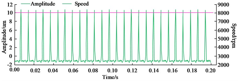
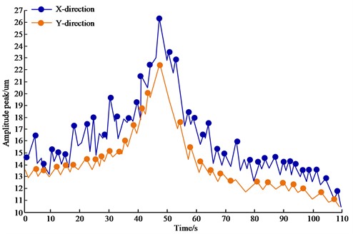
As shown in Fig. 9, the vibration amplitude showed periodic changes, with a maximum value of 11 um. The actual speed monitoring value remained stable at 8000 rpm. During the frequency sweep process, the monitoring results of vibration peak values are shown in Fig. 10.
In Fig. 10, by detecting the peak value of vibration, the vibration situation of the equipment could be monitored in real-time and the data could be transmitted to the voltage output program. When the vibration value exceeded the preset threshold, the voltage output program could take corresponding control measures, such as interrupting the coil current, to prevent friction and collision between the shaft and the inner ring of the electromagnetic bearing.
Fig. 10Monitoring results of vibration peaks and peaks
5. Conclusions
This study optimized the design and experimental analysis on the double rotor connection structure with circular end teeth and electronic sensors. Firstly, by optimizing the structure of the arc end tooth connection, the strength and reliability of the connection have been improved, providing reliable basic data for subsequent research on the connection damping and stiffness of the arc end tooth connected rotor under complex loads. The experimental results showed that a direct correlation between the preload force and the maximum stress on the circular end teeth. At zero speed, the maximum stress value was approximately 280 MPa. The optimized electromagnetic actuator showed good vibration control effect in the centrifuge, reducing vibration peaks by 47 % at low speeds and significantly improving vibration control at high speeds. In addition, the study utilized self-developed programs for software data collection and optimized the installation of sensors on the test bench to provide dependable basic data for future experiments. The experimental results showed that the vibration amplitude exhibits periodic changes, reaching a maximum value of 11 um. The actual speed monitoring value was maintained at 8000 rpm, demonstrating high stability. By detecting the peak value of vibration, the vibration situation of the equipment could be monitored in real time and the data can be transmitted to the voltage output program. When the vibration value exceeded the preset threshold, the voltage output program could take corresponding control measures, such as interrupting the coil current, to prevent friction and collision between the shaft and the inner ring of the electromagnetic bearing. In summary, this study conducted optimized design and experimental analysis of the circular arc end tooth dual rotor connection structure and electronic sensors. This provides strong support for improving the vibration control effect of electromagnetic actuators under complex working conditions and predicting the dynamic characteristics of rotor systems. These research results to some extent contribute to promoting technological progress in electromagnetic actuators, arc end tooth connection structures, and related fields, providing useful references for practical engineering applications. The limitation of this study is that only one circular arc end tooth double rotor connection structure has been designed. In future research, different types of circular arc end tooth connection interface rotors can be designed, and through comparative analysis, better performance connection structures can be obtained to further improve the performance of the rotor.
References
-
L. Wen, Z. Chen, and A. Fuentes-Aznar, “Computerized design, simulation of meshing and stress analysis of non-generated double circular-arc helical gear drives with different combinations of transverse pressure angle,” Mechanism and Machine Theory, Vol. 170, No. 1, p. 104683, Apr. 2022, https://doi.org/10.1016/j.mechmachtheory.2021.104683
-
D. Changbin, L. Yongping, and W. Yongqiao, “Dynamic meshing characteristics of elliptic cylinder gear based on tooth contact analysis,” International Journal of Engineering, Vol. 33, No. 4, pp. 676–685, Apr. 2020, https://doi.org/10.5829/ije.2020.33.04a.19
-
R. Gołębski and P. Boral, “Study of machining of gears with regular and modified outline using CNC machine tools,” Materials, Vol. 14, No. 11, p. 2913, May 2021, https://doi.org/10.3390/ma14112913
-
P. Bari, M. Law, and P. Wahi, “Geometric models of non-standard serrated end mills,” The International Journal of Advanced Manufacturing Technology, Vol. 111, No. 11-12, pp. 3319–3342, Nov. 2020, https://doi.org/10.1007/s00170-020-06093-0
-
C. Lin, Y. Wang, Y. Hu, and Y. Yu, “Compound transmission principle analysis of eccentric curve-face gear pair with curvilinear-shaped teeth based on tooth contact analysis,” Proceedings of the Institution of Mechanical Engineers, Part C: Journal of Mechanical Engineering Science, Vol. 236, No. 8, pp. 4026–4037, 2022, https://doi.org/10.1177/0954406221104707
-
T. Tang, J. Li, J. Wang, K. Xiao, and Y. Han, “Double-circular-arc tooth profile design and parametric analysis on the comprehensive performance of the harmonic drive,” Proceedings of the Institution of Mechanical Engineers, Part J: Journal of Engineering Tribology, Vol. 236, No. 3, pp. 480–498, 2022, https://doi.org/10.1177/1350650121101963
-
Q. Meng, Y. Zhao, J. Cui, S. Mu, and G. Li, “Kinematic-geometric lubrication theory and its application to arc-toothed cylindrical worm drive,” Journal of Tribology, Vol. 144, No. 11, p. 11160, Nov. 2022, https://doi.org/10.1115/1.4054541
-
Y. Liu, Y. Zhao, X. Chen, and G. Li, “Meshing theory of axial arc tooth profile cylindrical worm drive,” Advances in Mechanical Engineering, Vol. 13, No. 4, pp. 1–12, 2021, https://doi.org/10.1177/16878140211012
-
D. Ma, Y. Liu, Z. Ye, Y. Wei, and J. Liu, “Analysis of the tooth surface contact area of a circular-arc-tooth-Trace cylindrical gear under load,” Transactions of FAMENA, Vol. 45, No. 1, pp. 79–94, May 2021, https://doi.org/10.21278/tof.451018220
-
V. Syzrantsev and K. Syzrantseva, “Study of geometric characteristics of the arc teeth semi-rolled cylindrical gear meshing,” FME Transactions, Vol. 49, No. 2, pp. 367–373, Jan. 2021, https://doi.org/10.5937/fme2102367s
-
D. Li, Y. Zhao, S. Zhu, H. Luan, and Q. Ma, “Sleeve-type torque sensor based on effect of strain induction applied to wide-blade drill rod,” Sensors and Materials, Vol. 32, No. 4, p. 1235, Apr. 2020, https://doi.org/10.18494/sam.2020.2533
-
Q. Wang and X. Wang, “A fault detection diagnosis predict observer based on resource allocation network, 96-101.,” Mechatronic Systems and Control, Vol. 50, No. 2, pp. 96–101, Jan. 2022, https://doi.org/10.2316/j.2022.201-0277
-
R. K. Vashisht and Q. Peng, “Fractional calculus-based energy efficient active chatter control of milling process using small size electromagnetic actuators,” Journal of Vibration and Acoustics, Vol. 143, No. 1, pp. 1–33, Feb. 2021, https://doi.org/10.1115/1.4047703
-
S. Wang, Z. Weng, and B. Jin, “A performance improvement strategy for solenoid electromagnetic actuator in servo proportional valve,” Applied Sciences, Vol. 10, No. 12, p. 4352, Jun. 2020, https://doi.org/10.3390/app10124352
-
A. R. Singh, T. Bashford-Rogers, D. Marnerides, K. Debattista, and S. Hazra, “HDR image-based deep learning approach for automatic detection of split defects on sheet metal stamping parts,” The International Journal of Advanced Manufacturing Technology, Vol. 125, No. 5-6, pp. 2393–2408, Jan. 2023, https://doi.org/10.1007/s00170-022-10763-6
-
J. Wang, G. Xu, C. Li, G. Gao, and Q. Wu, “SDDet: An enhanced encoder-decoder network with hierarchical supervision for surface defect detection,” IEEE Sensors Journal, Vol. 23, No. 3, pp. 2651–2662, Feb. 2023, https://doi.org/10.1109/jsen.2022.3229031
-
R. Suk and G. Altintaș, “Behavior of multidirectional friction dampers,” Journal of Vibration and Control, Vol. 26, pp. 1969–1979, 2020, https://doi.org/10.1177/107754632090997
-
Y. Li, L. Liu, S. Yang, Z. Ren, and Y. Ma, “A multi-objective topology optimization methodology and its application to electromagnetic actuator designs,” IEEE Transactions on Magnetics, Vol. 56, No. 2, pp. 1–4, Feb. 2020, https://doi.org/10.1109/tmag.2019.2952834
-
D. Aikhuele, “Development of a statistical reliability-based model for the estimation and optimization of a spur gear system,” Journal of Computational and Cognitive Engineering, Vol. 2, No. 2, pp. 168–174, Mar. 2022, https://doi.org/10.47852/bonviewjcce2202153
-
T. A. Waziri and A. Ibrahim, “Discrete fix up limit model of a device unit,” Journal of Computational and Cognitive Engineering, Vol. 2, No. 2, pp. 163–167, May 2022, https://doi.org/10.47852/bonviewjcce2202166
-
Y. Fang, B. Luo, T. Zhao, D. He, B. Jiang, and Q. Liu, “ST‐SIGMA: spatio‐temporal semantics and interaction graph aggregation for multi‐agent perception and trajectory forecasting,” CAAI Transactions on Intelligence Technology, Vol. 7, No. 4, pp. 744–757, Nov. 2022, https://doi.org/10.1049/cit2.12145
About this article

The authors have not disclosed any funding.
The datasets generated during and/or analyzed during the current study are available from the corresponding author on reasonable request.
The authors declare that they have no conflict of interest.
