Abstract
In order to investigate the effects of load and system parameters on the planetary gear system, this paper develops a nonlinear time-varying dynamic model of a 12-degree-of-freedom planetary gear system. The model is employed to analyze the influence of load and system parameter variations on the meshing force, kinetic energy, strain energy, and load-sharing coefficient. The results demonstrate that the unbalance exacerbates tooth collision and increase the peak meshing force. Increasing the load will reduce the tooth collision and enhances the load sharing coefficient of the system. Decreasing the tooth side clearance, the unilateral tooth collision will be transformed into bilateral collision and mitigates the fluctuation of the meshing force. Additionally, increasing the transmission error amplifies the magnitude and fluctuation of the strain energy but reduces the system’s load-sharing coefficient.
Highlights
- Unbalance exacerbates gear tooth collisions, increasing peak meshing forces and generating side-band frequencies via multi-axis excitation modulation.
- Increasing load reduces tooth collisions and enhances load-sharing, while reducing tooth side clearance shifts unilateral to bilateral collisions, amplifying meshing force fluctuations.
- Kinetic energy decreases with larger tooth clearance, while strain energy and its fluctuations escalate with higher transmission errors and loads, impacting system longevity.
- Higher loads significantly improve load-sharing coefficient, whereas transmission errors degrade it.
1. Introduction
With the development of mechanical equipment towards large-scale, high-reliability, high-accuracy and long-life, the requirements for the dynamics of planetary gear systems are also increasing. Accurately predicting the dynamic performance of these systems has become increasingly important. However, the variation of system parameters such as unbalance, tooth side clearance, variations in system parameters, such as unbalance, tooth side clearance, and transmission error, significantly increase the complexity of studying gear system dynamics. Meshing characteristics are a critical performance metric in planetary gearing systems, as they directly affect the stability, noise and lifespan of the transmission system. Since load and system parameters are key factors influencing the meshing characteristics of planetary gears, it is essential to study their effects on these characteristics.
In recent years, many scholars have carried out various researches on planetary gearing systems. Huachao Xu [1] et al. established a dynamic model of a planetary gear system with rolling bearings, analyzed the dynamic behavior of the system and the dynamic contact load of the rolling elements, and revealed the dynamic influence mechanism between the planetary gears and the rolling bearings. Tan Jianju [2] et al. used the concentrated mass method to establish a rigid-flexible coupled dynamics model of a planetary gear set, analyzed the dynamics response of the system based on the model, and summarized the effects of input torque changes on the system vibration. Siyu Wang [3] et al. developed a nonlinear dynamics model of a planetary gearbox system taking into account several nonlinear factors, and utilized the numerical integration method via Lunger-Kutta to analyze the dynamics response when the input speed is varied. Zhang [4] et al. developed a free vibration dynamics model considering time-varying meshing stiffness to study the modal characteristics of planetary gear system, and investigated the effect of time-varying meshing stiffness on its intrinsic characteristics. Wang S. [5] et al. built a GTF gearbox systems dynamics model, the effects of the double rotor bearings on the dynamic performance of the GTF transmission system are analyzed, especially the effects of the bearing positions on the load sharing performance of the GTF gearbox star gear transmission system. Cheng Wang [6] analyzed the effect of planetary gears and star gears on the transmission efficiency by taking the closed differential double helical gear train as the object of study. Zhu L. S. [7] et al. based on the finite element method A pair of generalized axial-oscillating multi-degree-of-freedom coupled helical gears meshing dynamics model was established, and the effects of meshing stiffness and meshing damping on the intrinsic characteristics and transient response of the system were analyzed. Jie Yang [8] et al. established a coupled dynamics model of a herringbone gear rotor system supported by axial bearings, and the effect of bearing ripple degree on the system is analyzed by comparing the two system dynamics accordingly at health and failure. Zou HaoRan [9] et al. developed a coupled dynamics model of GTF planetary gearing system considering time-varying meshing stiffness and transmission error, based on which the effects of different topological modification schemes on the dynamic characteristics of the system were investigated. Ali Tatar [10] et al. assumed the gears to be rigid and the bearings to be flexible, established a finite element dynamics model of a planetary gearbox, analyzed the intrinsic properties of the system, and found that the gyroscopic effect is more significant on the planetary gearbox. Hao Dong [11] et al. established a static load sharing calculation model in order to analyze the load equalization characteristics of an aero-engine reducer, and analyzed the effects of manufacturing and installation errors on the load sharing factor. Siyu Wang [12] et al. proposed an improved nonlinear dynamics model for GTF gearboxes that includes nonlinear factors in order to make the study closer to the reality. By analyzing the dynamic characteristics, it was found that the nonlinear dynamics behavior of the system would change with the change of tooth collision state. Shuai Mo [13] et al. developed a refined new dynamic model for the vibration and intrinsic characteristic analysis of a double-helix star gear transmission system. Taking a certain type of aero-engine gear transmission system as the research object, the validity of the dynamics model is verified through calculation. Fang Guo [14] et al. developed a dynamic model of a generalized planetary gearing system containing time-varying meshing stiffness and load balance, and analyzed the effects of eccentricity error and operating frequency variation on the bifurcation characteristics of the system. Haoran Zou [15] et al. establish an improved dynamics model considering the elastic deformation of the toothed ring, and use it to compare with that without considering the elastic deformation of the toothed ring. Wei Liu [16] et al deduced the translation-torsion equations of motion of the new elastic discretization model considering the sliding friction, and investigated the effect of the sliding friction on the time-varying lattice stiffness. Dong Li [17] analyzed the distribution of loads in the planetary gear system as well as the effect of mounting errors on power distribution based on the efficiency calculation model. Lokaditya Ryali [18] et al. developed a three-dimensional dynamic model of a planetary gear system considering the effects of internal and external excitations, and analyzed the dynamic response of the system and the distribution of gear stresses under different operating conditions. Hongyuan Zhang [19] et al. established a nonlinear dynamic model of a planetary gear system with multiple degrees of freedom, and numerically solved it by the Lunger-Kutta method. The effects of nonlinear factors on the dynamic response of the system and the effects of internal and external excitations on the main frequencies of the system are analyzed. Lanlan Hou [20] et al. developed an analytical model of a nonlinear GTF planetary gear system and analyzed the nonlinear properties of the system by means of bifurcation diagrams and Poincaré diagrams, and also demonstrated that the chaotic path of the intermittent. Jungang Wang [21] et al. conducted an in-depth investigation into the evolution of load-sharing characteristics in planetary gear systems under the coupled effects of rotational speed variations and internal excitations. Yifan Huangfu [22] et al. proposed a wear prediction model for planetary gear systems. The model’s prediction accuracy and reliability were systematically validated through a combined approach of finite element simulation and experimental testing. Gao Dingqiang and Gao Zhiyu [23] jointly established a nonlinear dynamic model of a multi-degree-of-freedom two-stage helical gear planetary system and systematically investigated the influence mechanisms of nonlinear factors on the system’s dynamic characteristics. Li Shenlong [24] et al. constructed a multi-gear planetary gear train model by considering the positional relationships between the planetary gears and the planetary shafts, and conducted an in-depth analysis of the influence of positional errors on the system’s vibration characteristics.
In summary, scholars have conducted a lot of research on planetary gear dynamics modeling and the effect of nonlinear factors on the overall vibration of the gearbox. However, studies on the influence of load and system parameters on the meshing characteristics of the planetary gear system are relatively rare. Meshing characteristics in planetary gear transmission systems significantly impact the operational stability, noise level, and lifespan of the system. Therefore. This paper establishes a nonlinear time-varying dynamics model of planetary gear system. considering coupling factors of unbalance, time-varying mesh stiffness, tooth side clearance and transmission error, and studies the effects of unbalance, load, tooth side clearance and transmission error on the meshing characteristics of the planetary gear system are investigated.
2. Planetary gear system dynamics modeling
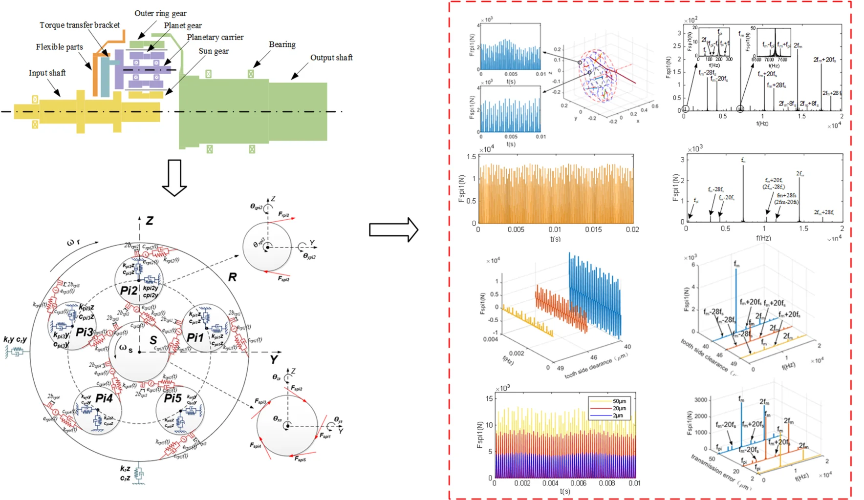
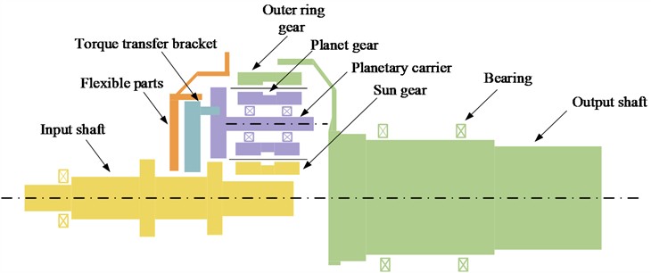
The structure of the planetary gear rotor system is shown in Fig. 1. It primarily consists of consists of the input shaft, the sun gear (), five identical planetary gears (), ring (), the planetary carrier, the torsion bracket, and the flexible parts connected with the torsion bracket. The sun gear is a floating part, while the ring is a semi-floating part. The planetary carrier is connected to the torsion bracket and the flexible parts, forming a cantilever beam-like structure. The sun gear, the five planetary gears and the ring are all herringbone gears. The sun gear is centrally located, and the five planetary gears are positioned at 18°, 90°, 162°, 234°, and 306° around the sun gear, respectively. After the gravity and torque generated by the meshing of the entire gearbox are transmitted to the flexible parts through the torsion bracket, the flexible parts further transfer them to the casing. The power transmission path of the system is as follows: the input shaft delivers the power to the sun gear via the spline, the sun gear then transfers the force to the planetary gears through gear meshing; the planetary gears subsequently transmit the power to the ring gear through gear meshing; finally, the ring gear, which is bolted to the output shaft, serves as the output.
Fig. 1Sketch of the structure of the planetary gear system
Considering the actual structure and operation effect, in order to make the analysis results more focused on the gear radial vibration, axial vibration and small swing on the overall vibration of the impact as well as to improve the efficiency and stability of the calculation, this paper uses the following assumptions in the system modeling:
(1) The bearing housing and other parts and foundation are rigid.
(2) The meshing force of the gear pair always lies in the meshing plane.
(3) Changes in gear support stiffness are ignored [25-26].
Based on the traditional numerical simulation modeling approach, the shaft segments of the rotor system are modeled using Timoshenko beam units. The left and right nodes of the beam unit are defined as Node and Node , respectively. Each shaft segment element has a total of 12 degrees of freedom, defined as follows:
The equation of motion of the shaft segment unit can be expressed as:
where , , , are the mass matrix, damping matrix, gyroscopic force matrix, and stiffness matrix of the axial segment unit, respectively, is the rotational speed of the axial segment unit, and is the external load of the axial segment unit.
The gears are modeled using the beam unit equivalent method. Under the premise of ensuring similarity in geometrical parameters and dynamic characteristics between the actual model and the theoretical model, the sun gear, planetary gears, and ring are simplified. The simplification method involves dividing the nodes of the beam unit at locations such as bearing support, gear meshing, and mutation of the shaft segment, and so on.
The planetary gear shaft are mounted on a fixed planetary carrier, which is connected to a flexible part, each planetary gear is supported by two angular contact ball bearings, For the convenience of numerical simulation, the planetary carrier, the flexible component, and the bearings are collectively represented as two sets of support stiffnesses [27]. The input shaft solely transmits torque to the whole system and does not provide any additional support; therefore, it is omitted in the modeling process.
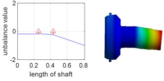
Since dynamic simulation analysis of multi-gear systems is generally challenging and prone to convergence difficulties, and considering that the dynamic characteristics of the system are determined by the modal properties of each subsystem, single-axis modal analysis was adopted to validate the accuracy of the model. Single-axis modal and natural frequency analyses were performed for the planetary gear shafts and the ring shaft respectively, and the results were compared and verified using Ansys Workbench. During the analysis with Ansys Workbench, the deformation effect caused by the disc structure of the two shafts is ignored, Table 1 and Table 2 present the first two orders of natural frequencies of the two shafts obtained by the two different methods, it can be observed that the results from both methods show minimal differences. The results of the planetary gear shaft and the ring shaft are illustrated in Fig. 2 and Fig. 3, respectively. From the figures, it is evident that the first two orders natural frequencies of the planetary gear shaft and the ring shaft obtained from the numerical model are in close agreement with those obtained from Ansys Workbench. This indicates that the numerical model is highly accurate. Consequently, empirical formulas were used to calculate the gear meshing stiffness, which was then integrated with the constructed single-axis numerical model, based on this, a multi-axis finite element numerical model is further established.
Table 1The first two orders of natural frequency of planetary gear shaft
Order | Precession direction | Anays results (Hz) | Numerical results (Hz) | Error (%) |
First | Forward precession | 805.2 | 764.0 | 5.09 |
Backward precession | 759.5 | 720.6 | 5.12 | |
Second | Forward precession | 1317.7 | 1260.5 | 4.34 |
Backward precession | 1230.3 | 1177.2 | 4.31 |
Table 2The first two orders of natural frequency of ring axis
Order | Precession direction | Anays results (Hz) | Numerical results (Hz) | Error (%) |
First | Forward precession | 211.6 | 211.7 | 0.05 |
Backward precession | 175.0 | 175.5 | 0.27 | |
Second | Forward precession | 710.9 | 629.2 | 11.5 |
Backward precession | 674.2 | 608.8 | 9.6 |
Fig. 2First two orders of vibration patterns of planetary gear shafts
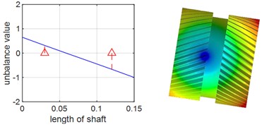
a) First-order forward precession
b) First-order backward precession
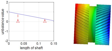
c) Second-order forward precession
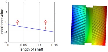
d) Second-order backward precession
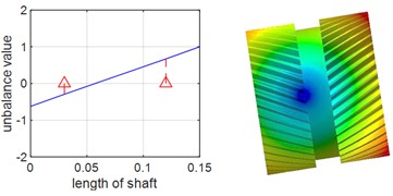
Fig. 3First two orders of vibration patterns of ring shaft
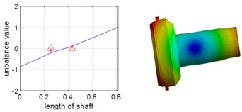
a) First-order forward precession
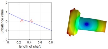
b) First-order backward precession
c) Second-order forward precession
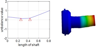
d) Second-order backward precession
The dynamics model of the star gear system is shown in Fig. 4, where , , , , represent five planetary gears. denotes the sun gear. represents outer gear ring, , (1, 2, 3, 4, 5) are the meshing stiffness and meshing damping between the planetary gear and the sun gear respectively. and (1, 2, 3, 4, 5)represent the meshing stiffness and meshing damping between the sun gear and the planetary gears respectively, while and (1, 2, 3, 4, 5) represent the meshing stiffness and meshing damping between the ring gear and the planetary gears, respectively. , , and (1, 2, 3, 4, 5) are the support stiffness and support damping of the ring gear and planetary gears in the horizontal and vertical directions, respectively. and (1, 2, 3, 4, 5) represent the transmission error between the planetary gears and the sun gear and the transmission error between the planetary gears and the ring gear. and (1, 2, 3, 4, 5) denote the unilateral tooth side clearance between the planetary gears and the sun gear and between the planetary gears and the ring gear, respectively. and (1, 2, 3, 4, 5) represent the external meshing force between the planetary gear and the sun gear and the internal meshing force between the planetary gear and the ring gear, respectively. The superscripts and in Fig. 4(b) indicate the left-side gear and the right-side gear, respectively.
Fig. 4Dynamic model planetary gear transmission system
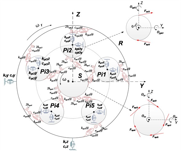
a) Schematic of the left end face of the dynamic model of the planetary gear transmission system
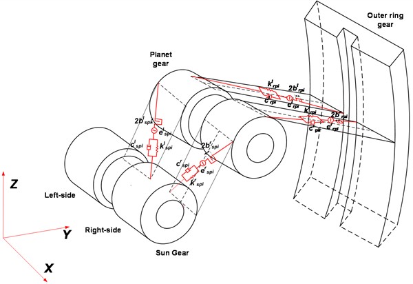
b) 3D schematic diagram of the dynamics model of the planetary gear transmission system
During gear meshing, the engagement of gear teeth alternates, causing the number of teeth simultaneously in contact to vary periodically over time. Additionally, the alternation between single and double tooth meshing leads to periodic changes in the overall meshing stiffness of helical gears, thereby inducing dynamic stiffness fluctuations. Consequently, the stiffness characteristics of the mesh exhibit distinct cyclic patterns during transmission, which can be effectively represented using a Fourier series [28], expressed as:
where is the average meshing stiffness , , are the Fourier series, is the phase angle, is the meshing frequency, and is expressed as:
where, is the gear speed and is the number of gear teeth.
Since the system is more sensitive to the dynamic characteristics in the low frequency range, the effect of higher order terms is usually smaller, and to improve the computational efficiency, the Fourier series of the second order and above is ignored, it can be written as:
where is the stiffness fluctuation amplitude.
Gear transmission error primarily arises from inaccuracies in design, manufacturing, and assembly, leading to positional deviations during gear meshing that result in tooth impacts. This error exhibits periodicity and can be accurately modeled using a Fourier series formulation [29], as following:
where is the average transmission error , is the Fourier series.
Similarly, if the Fourier series of second order and higher are neglected and the mean error , it can be written as:
where, is the amplitude of transmission error fluctuations
Due to the need for lubrication, as well as gear manufacturing and installation errors, mutual meshing between the teeth of the wheel there is a tooth side clearance. A tooth side clearance exists between the meshing gear teeth. The presence of tooth side clearance alters the contact state between the gear teeth, leading to continuous impacts that significantly affect the dynamic characteristics of the gear system, The gear deflection function can be expressed as [30]:
where is the unilateral tooth side clearance, is the relative meshing line length.
3. Planetary gear system dynamics modeling
All gears in the system are herringbone gears, with their geometric parameters listed in Table 3 and operational parameters detailed in Table 4. The meshing of herringbone gears can be likened to two helical gears engaging simultaneously but rotating in opposite directions [31]. As a result, the dynamic equations for one side can be derived from those of the other. Due to space constraints, this paper focuses solely on deriving the dynamic equations for the left-side gears of the planetary gear system. Based on Fig. 4(a), the dynamic equations for the planetary gear and the sun gear are obtained as follows:
Planetary gear :
Sun gear:
The dynamic equations for the other gears are similar, and thus can be expressed as:
Planetary gear :
Planetary gear :
Planetary gear :
Planetary gear :
Ring:
where , , , , () are the stiffness of the gear in the , , direction and around the , axis, respectively, and , , , , () are the damping of the gear in the , , direction and around the , axis, respectively, , (, ) are the meshing stiffness and meshing damping of gears and gears , respectively, is the helix angle ( if the gears are rotated right, then; if the gears are rotated left, then), and are the input torque moment and system load, is the gap function, which is denoted by:
where is the unilateral tooth clearance between gear and gear .
is the directional angle from the positive direction of the -axis to the meshing surface, which is related to the direction of rotation of the driving gear, let denote the pressure angle and is the direction angle of the gear. Thus, can be expressed as.
When the gear pair is an external meshing pair:
When the gear pair is an internal mesh pair, is expressed as:
Each gear has three translational degrees of freedom , , and three rotational degrees of freedom , , , Thus the planetary gear system has 42 degrees of freedom, can be represented as follows:
Therefore, Eqs. (9-15) can be written as:
where is the mass matrix of the gear system, is the support damping matrix of the gear system, is the support stiffness matrix of the gear system, is the meshing damping matrix of the gear system, is the meshing stiffness matrix of the gears, is the backlash function with respect to , is the external load.
Table 3Gear geometric parameters
Sun gear | Planetary gear | Ring | |
Number of teeth | 48 | 37 | 122 |
Modulus (mm) | 3.5 | ||
Pressure angle () | 22.5 | ||
Helix angle () | 20 | ||
Table 4Operating parameters of the planetary gear system
Working speed (r/min) | Rated load (N⋅m) |
9000 | 9840 |
4. Mesh characterization of star gear system
In the actual processing and manufacturing process, it is challenging to completely eliminate unbalance within the planetary gear system. Additionally, due to the complex and unique nonlinear meshing characteristics of the planetary gear system, the meshing force exhibit highly complex nonlinear behavior. The unbalanced vibration of the rotor system significantly affects these characteristics.
The formula for the permissible unbalance amount of the shaft segment is:
where is the unbalance amount, m is the mass of the shaft segment, is the permissible unbalance rate, which can be calculated using the following formula:
where, represents the rotor balance quality, typically G6.3 for GTF rotors, and is the maximum operating angular velocity of the rotor.
To investigate the impact of unbalance on the meshing force, it is assumed that the unbalance is increased to 10 times the permissible unbalance and exists only on the five planetary gears and the ring gear. Using unbalance loading case 1 in Table 5 (where ‘○’ indicates inclusion and ‘×’ indicates exclusion) as an example, the external meshing force between the planetary gears and the sun gear, as well as the internal meshing force between the planetary gears and the ring gear, are analyzed. Under the light load condition of operating speed and 1 % rated load, the nonlinear time-varying model of the planetary gear system proposed in this paper is utilized to obtain the time-domain signals and frequency-domain signals of and respectively, The results are shown in Fig. 5.
Table 5Degree of unbalance loading method
Pi1 | Pi2 | Pi3 | Pi4 | Pi5 | R | |
Degree of unbalance (g.mm) | 750 | 750 | 750 | 750 | 750 | 5011 |
Initial phase (deg) | 0 | 0 | 0 | 0 | 0 | 0 |
Case 1 | ○ | ○ | ○ | ○ | ○ | ○ |
Case 2 | ○ | × | × | × | × | × |
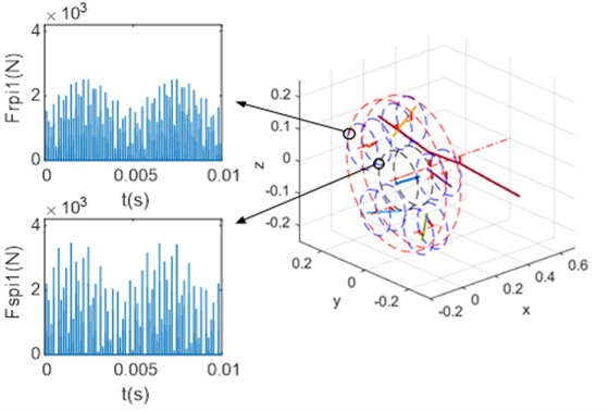
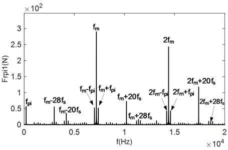
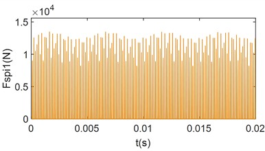
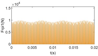
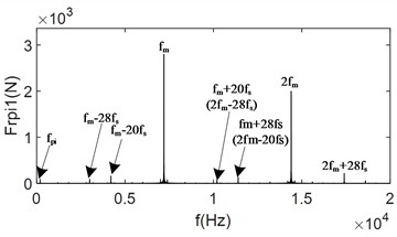
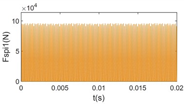
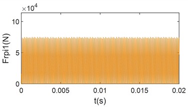
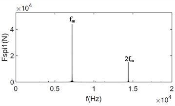
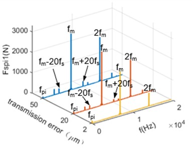
Fig. 5Time and frequency domain plots of meshing force for degree of unbalance loading case 1

a) Time-domain signals for the meshing force and
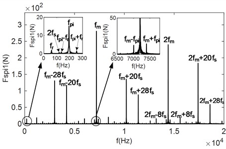
b) Frequency-domain signal of the meshing force
c) Frequency-domain signal of the meshing force
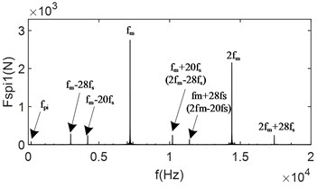
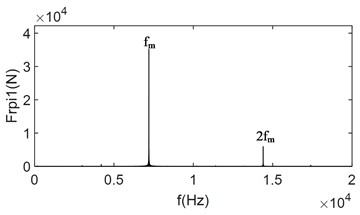
Fig. 5(a) shows the time-domain plots of the meshing forces and . It can be observed that under the influence of multiple unbalanced excitations, the meshing forces and exhibit significant collisions with a certain periodicity. Fig. 5(b) shows the frequency-domain plots of the meshing force . From the figure, it is evident that the frequency-domain signal of the meshing force mainly consists of the unbalanced excitation (194.6 Hz), (59.1 Hz) and its multiplicative frequency, the meshing frequency (7200 Hz) and its multiplicative frequency, as well as some side-band frequencies, for example, near , there are frequencies that differ from it by integer multiples of the sun gear rotational frequency (150 Hz). Additionally, in the low-frequency region, frequencies that differ from by integer multiples of are observed. Fig. 5(c) shows the frequency-domain plot of the meshing force , whose frequency-domain signal is similar to that of the meshing force . The same unbalanced excitations and appear in the low-frequency region. In the high-frequency region, besides the meshing frequency and the side-band frequencies centered around the meshing frequency with intervals of integer multiples of and , side-band frequencies centered around the meshing frequency with intervals of also present. By analyzing the side-band frequency intervals of the frequency-domain signals in Figs. 5(b) and 5(c), the modulation mechanism of the meshing side-band frequency in the planetary gear system under multi-axis unbalance can be deduced. Specifically, the meshing force is first modulated by the rotational frequency of the sun gear, then by the unbalanced excitation of the planetary gears, and finally by the unbalanced excitation of the ring gear. Therefore, the side-band frequency , which results from three frequency modulations centered on the meshing frequency and its octave, can be expressed as:
where , , are non-negative integers.
To investigate the impact of uniaxial imbalance on both internal and external meshing forces, this paper employed unbalance loading mode 2 from Table 3. Specifically, the examined the external meshing force between the planetary gear and the sun gear, as well as the internal meshing force within the ring gear, were examined. Using the nonlinear time-varying model of the planetary gear system developed in this study, time-domain and frequency-domain signals of the system were obtained at operational speed and under a light load of 1 % of the rated capacity. These results are depicted in Fig. 6.
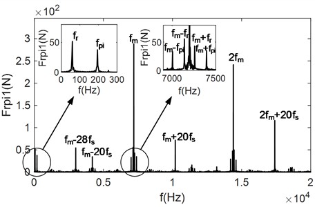
Fig. 6 shows the time and frequency domain plots of the meshing force under the unbalance loading mode 2, where only the planetary gear exhibits unbalance. Specifically, when the loading mode 2 is adopted, the collision between the gear teeth of the external meshing force is more intense compared to that for internal meshing force . However, overall, the meshing forces exhibit a more uniform variation compared to the case of multi-axis unbalance. The frequency-signal primarily consists of the excitation frequency due to the unbalance of the planetary gear , the mesh frequency and its multiplicative frequency, as well as some sideband frequencies.
Comparing Fig. 5(a) and Fig. 6(a), it can be found that the amplitude of increases due to the absence of the unbalance excitation from the other axes, while the collision between the planetary gear and the sun gear becomes more intense. This indicates that the unbalance vibration of each axis not only exacerbates the collision between the teeth of the gears on that axis, increasing the peak meshing load, but also affects the other axes. Due to the absence of unbalance, the amplitude of is slightly decreases, the collision between the gear teeth is reduced, and the meshing force becomes more uniform. From Figs. 6(b) and (c), it can be seen that when the planetary gear exhibit unbalance, the frequency-domain signals of the internal and external meshing forces do not significantly. Compared with Figs. 5(b) and (c), the unbalance excitation of the ring gear disappears in the low-frequency region, the high-frequency region, the sideband frequencies centered around the meshing frequency are integer multiples of the meshing frequency. Specifically, the sideband frequency with an integer multiple of disappears, while the amplitude of the side-band frequency with integer multiples of and centered on the meshing frequency increases significantly. Therefore, it can evident that the magnitude of the side-band frequency is also closely related to the collision between the gear teeth. Similarly, analyzing the intervals between the side-band frequencies, the modulation mechanism of the meshing side-band frequencies in the planetary gear system under single-axis unbalance can be deduced. The meshing force is firstly modulated by the rotational frequency of the sun gear and then by the excitation frequency of the unbalance. The first modulated frequencies centered on the n-fold frequency of can be expressed as:
where is a natural number.
The frequency of the second modulation centered on can be expressed as:
where is a natural number, is either or .
Fig. 6Time and frequency domain plots of the meshing force for degree of unbalance loading case 2
a) Time-domain signals for the meshing force and
b) Frequency-domain signal of the meshing force
c) Frequency-domain signal of the meshing force
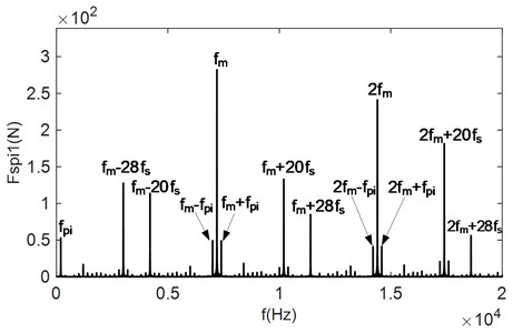
To more clearly compare the change of gear meshing force under the influence of load, only for the unbalance loading mode 2 shown in Table 3 is analyzed. The load torque is adjusted to 10 % of the rated load and 2 times the rated load, respectively, to obtain the time-domain and frequency-domain signals of the meshing forces and , as shown in Fig. 7.
In Fig. 7, when the load is increased from 1 % of the rated load to 10 % of the rated load, The average meshing forces increase significantly, and the collisions still occur. However, compared to Fig. 6, the collision phenomenon is reduced, and the variation of the meshing force within the meshing period is more uniform. From Fig. 7(c) and Fig. 7(d), it can be observed that the frequency-domain signals are still dominated by the meshing frequency and its octave. Additionally, the frequencies resulting from the first and second modulations of the meshing frequency are present. However, compared with Fig. 6(b) and Fig. 6(c), the amplitude of the side-band frequencies is significantly reduced, and their magnitudes are much smaller than the center frequency. This indicates that the load has a certain inhibitory effect on the side-band frequencies. This is because the increase load prolongs continuous meshing time between the gear teeth, and as the load increases, collisions between the meshing tooth surfaces disappear. From Fig. 7(e) and Fig. 7(f), it can be seen that when the system load increases to 2 times the rated load, collisions between the gears disappears, and the gears enter into a continuous meshing state. The gear meshing force is further increases, and the meshing uniformity improves. The modulated side-band frequency disappears, and the unbalance excitation becomes much smaller than the mesh frequency and is negligible. This demonstrates that the collision between the gears are one of the main reasons for the generation of the side-band frequencies in the frequency-domain signals.
For the unbalance loading mode 1, the output load is set to be 1 % of the rated load, and the tooth side clearance of the gear pair is changed to 49 μm, 46 μm and 20 μm, respectively, and The results are shown in Fig. 8.
Fig. 7Time-domain and frequency-domain plots for changing load torque meshing force
a) Time-domain plot of at 10 % rated load
b) Time-domain plot of at 10 % rated load
c) Frequency-domain plot of at 10 % rated load
d) Frequency-domain plot of at 10 % rated load
e) Time-domain plot of at 2 times rated load
f) Time-domain plot of at 2 times rated load
g) Frequency-domain plot of at 2 time rated load
h) Frequency-domain plot of at 2 times rated load
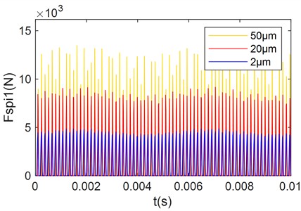
When the tooth side clearance is 200 μm, the meshing gears only have contact on one side of the tooth surface during the meshing process, while the other side remains free. Under reverse torque and vibration, the gears disengage, resulting in unilateral collision. Consequently, the meshing gears are in a unilateral reciprocating collision state of contact-meshing-bouncing. Within a certain range, the tooth side clearance does not significantly affect the meshing characteristics. However, when the tooth side clearance is reduced to 49 μm, as shown in Fig. 8, the displacement amplitude of the meshing teeth between the planetary gear and the sun gear under dynamic load may exceed the remaining clearance due to the reduced tooth side clearance. This causing the other side of the tooth surface to come into contact. As both sides of the tooth surface are alternately loaded, the collision transitions from unilateral to bilateral, leading to an increase in the peak meshing force and more pronounced periodicity. In the frequency-domain signal, the peak at the meshing frequency increases, while the peaks at other side-band frequencies show little change. When the tooth side clearance is further reduced to 46 μm, the meshing gear pair completely transitions from unilateral to bilateral collision. In the frequency-domain signal, the peak at the meshing frequency increases, while the peaks at other side-band frequencies remain largely unchanged. When the tooth side clearance is reduced to 40 μm, severe collisions occur between the meshing teeth, causing a sharp increase in the peak meshing force. In the frequency- domain signal, the frequency components are dominated by the meshing frequency itself, and the sideband frequencies almost disappear.
Fig. 8Effect of changing the tooth side clearance on meshing force
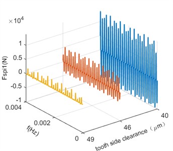
a) Time-domain signal of the meshing force
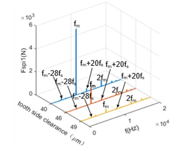
b) Frequency-domain signals of meshing force
In practical applications, gear manufacturing precision and assembly errors inevitably introduce transmission errors. Additionally, factors such as processing variations and tooth wear contribute to increased gear transmission errors. To investigate the influence of transmission errors on gear meshing forces, this paper utilize unbalance loading mode 2 as an example. The load is set to 10 % of the rated capacity, and the amplitudes of gear pair transmission errors are varied to 2 μm, 20 μm, and 50 μm. The results are shown in Fig. 9.
Fig. 9Effect of transmission error on gear meshing force
a) Time-domain signal of the meshing force
b) Frequency-domain signals of the meshing force
Fig. 9 demonstrates that transmission error significantly influences gear meshing characteristics. Smaller fluctuations in transmission error result in reduced gear tooth excitation, thereby minimizing variations in gear meshing force. Conversely, an increasing in the amplitude of transmission error fluctuations correlates with heightened fluctuations in gear meshing force. When the transmission error excitation on gear teeth reaches a critical level during meshing, it can cause teeth impacts. As transmission error further increases, the amplitude of gear meshing force amplitude gradually rises. In cases without tooth collisions, the frequency-domain signal of meshing force primarily consists of the meshing frequency and its harmonics. Conversely, tooth collisions introduce modulated side-band frequencies, with their amplitudes increasing in tandem with the transmission error fluctuations.
5. Analysis of kinetic and strain energy and load equalization factor for planetary gear system
The strain energy and kinetic energy of a planetary gear system are important forms of energy in describing its operation and design, while the strain energy affects the stability and life of the system. The strain energy of a planetary gear system is primarily caused by the elastic deformation of the rotor, with the most significant contribution comes from the bending strain energy, expressed as:
where is the bending adaptive energy, , are the bending stiffness matrix and bending displacement matrix of the rotor, respectively.
The kinetic energy of the planetary gear system affects the dynamic response and energy conversion efficiency of the system, the kinetic energy of the star gear system mainly comes from its rotating parts, which is expressed as:
where is the kinetic energy, , are the mass matrix and velocity matrix of the rotor system.
To investigate the impact of load and system parameters on the kinetic and strain energy of the planetary gear system, two operating conditions were examined: ideal and actual states. In the ideal state, the system operates at the specified speed and load without transmission errors and with minimal tooth side clearance. In the actual state, the system operates under the rated load with transmission errors and a large tooth side clearance. according to Eq. (26), the kinetic energy of each gear shaft over one cycle was calculated for both the ideal and actual states. To facilitate identification, the gear shafts are defined by the names of their respective gears. The results are shown in Fig. 10, from which it can be observed that in the ideal state, the kinetic energy of the individual gear shafts increases, particularly for the ring gear and the sun gear, where the kinetic energy is relatively non-uniform.
To thoroughly investigate the influence of each system parameter on the kinetic energy, the kinetic energy of the sun gear is taken as an example, and the effects of different factors in the actual state is analyzed, and the results are shown in Fig. 11.
Fig. 11(a) shows the variation of kinetic energy of the shaft of the sun gear over one cycle by changing the tooth side clearance to 20 μm, 30 μm and 40 μm, respectively. From the figure, it can be observed that the kinetic energy of the sun gear decreases as decreases as the tooth side clearance increases, and the fluctuation of the kinetic energy decreases with the increase of the tooth side clearance.
Fig. 11(b) shows the variation of kinetic energy of the sun gear shaft over one cycle by changing the transmission error amplitude to 2 μm, 20 μm and 50 μm respectively. From the figure, it can be observed that the kinetic energy fluctuation will increase with the transmission error amplitude as the transmission error amplitude increases, but the degree of influence is smaller compared with that in Fig. 11(a).
Fig. 11(c) shows the variation of the kinetic energy of the sun gear shaft over one cycle by changing the load torque amplitude to 50 % of the rated load, 100 % of the rated load, and 200 % of the rated load, respectively. It can be observed that both the amplitude and fluctuation of the kinetic energy of the sun gear increase with the load.
Fig. 10Kinetic energy distribution of each gear shaft in two states
a) Ideal kinetic energy distribution of individual gear shafts
b) Kinetic energy distribution of individual gear shafts in the actual state
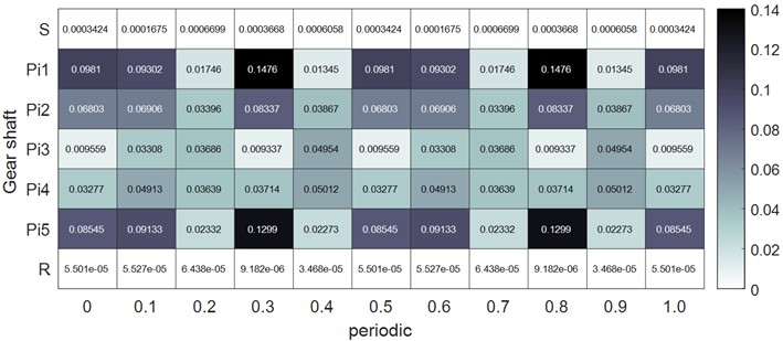
Strain energy is an important factor in the process of optimizing the design of gears and related components. Analyzing the distribution of strain energy in a planetary gear system and the effect of nonlinear factors on it is essential for understanding of the system performance. In this paper, the strain energy analysis of the planetary gear system supports is carried out. According to Eq. (27), the strain energy of each support over one cycle under two working conditions is calculated, and the results are shown in Fig. 12. Since most of the strain energy of the ring gear is stored within itself, the strain energy of the support of the ring gear is smaller compared to that of the planetary gear shaft supports. Additionally, the stiffness of the right bearing of the planetary gear shaft is smaller than that of the left bearing, resulting in higher potential energy in the right bearing compared to the left. Comparing Fig. 12(a) and Fig. 12(b), it can be observed that the fluctuation of the strain energy in the actual state is larger than that in the ideal state. To better understand the influence of the system parameters on the strain energy, the strain energy of the right bearing () of the sun gear shaft is analyzed as an example, and the results are shown in Fig. 13.
Fig. 11Effect of each system parameter on the kinetic energy of the sun gear axis
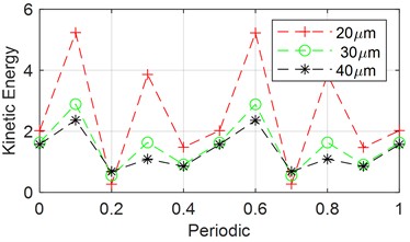
a) Changing the tooth side clearance
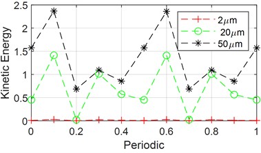
b) Changing the transmission error amplitude
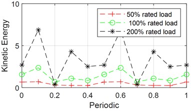
c) Change of load amplitude
Fig. 12Distribution of strain energy for each support in both states
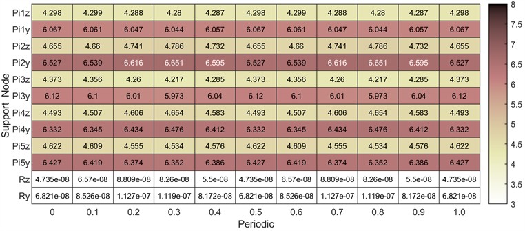
a) Distribution of strain energy at each supporting node under ideal conditions
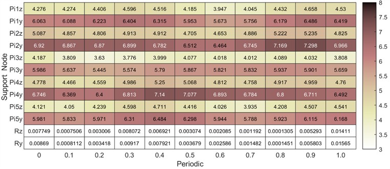
b) Distribution of strain energy at each supporting node in the actual state
Fig. 13(a) shows the variation of strain energy over one cycle by hanging the tooth side clearance to 20 μm, 30 μm and 40 μm. From the figure, it can be observed that the fluctuation of strain energy decreases as the tooth side clearance increases, while the amplitude of strain energy remains relatively unchanged.
Figure 13(b) shows the variation of strain energy over one cycle by changing the transmission error amplitude to 2 μm, 20 μm and 50 μm. From the figure, it can be observed that as the transmission error amplitude increases, the fluctuation of potential energy increases, and the amplitude of potential energy also rises to some extent. Compared with Fig. 12(a), the degree of influence is more significant.
Fig. 13(c) shows the variation of strain energy over one cycle by varying the load torque amplitude to 50 % of rated load, 100 % of rated load, and 200 % of rated load torque, respectively, and the amplitude of adaptive energy increases dramatically as the load increases and fluctuation increases.
Fig. 13Effect of system parameters on strain energy of planetary gear right support
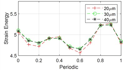
a) Changing the tooth side clearance
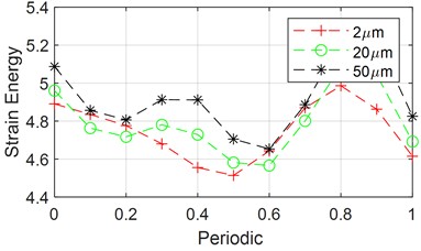
b) Changing the transmission error amplitude
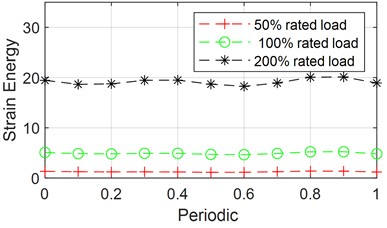
c) Change of load amplitude
In a planetary gear system, the load applied between each pair of meshing gear teeth exhibits non-uniform distribution. To quantify this, we introduce the load distribution coefficient, also known as the load sharing factor. The load sharing coefficient for the planetary gear system is defined as the moment of the meshing force divided by the average meshing force ratio. Ideally, uniform load distribution across the entire system results in a load sharing factor of 1, indicating optimal load equalization. Deviations from this ideal lead to varying degrees of load imbalance. The left and right external meshing and internal meshing equalization coefficients for each gear pair are defined as , , , where 1, 2, 3, 4, 5, and are expressed as:
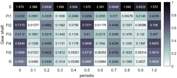
Fig. 14 illustrates the variation in load sharing coefficients for the left and right sides, as well as internal and external meshes of the planetary gear system, under two operating conditions: operating speed and rated load. As shown in Fig. 14(a), under ideal condition, the load sharing coefficients for the left and right sides, as well as internal and external meshing, exhibit cyclic variations. Although peak fluctuations remain relatively stable, differences in amplitudes are observed due to varying meshing phases. Conversely, in the actual operating state (see Fig. 14(b)), all load sharing coefficients increase significantly, accompanied by larger peak fluctuations. Overall, the load sharing coefficients for internal and external meshing on the left side are higher than those on the right side. This discrepancy is primarily attributed to the greater support stiffness of the left gear, which results in less effective load balancing.
Fig. 14Variation of load sharing coefficient with period for both cases
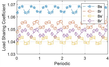
a) Ideal equalization factor
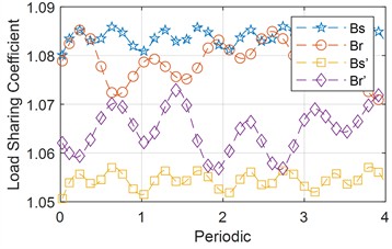
b) Load equalization factor in real terms
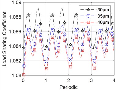
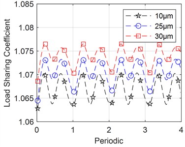
Fig. 15Effect of individual system parameters on load sharing coefficient
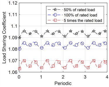
a) Change of load amplitude
b) Changing tooth side clearance
c) Changing the transmission error amplitude
To thoroughly examine the impact of each system parameter on load balancing properties, adjustments were made to tooth side clearance, load, and transmission error using the method of controlling variables. As an illustration, analyzed the external mesh load sharing coefficient was analyzed, and the outcomes are presented in Fig. 15.
In Fig. 15(a), the graph depicts the variation of the external mesh equalization coefficient over time for different loads. As the load increases, load sharing coefficient gradually converges to 1, indicating that higher loads improve load balancing properties.
In Fig. 15(b), the graph shows how the external mesh load sharing coefficient changes with cycle time for varying degrees of tooth side clearance. As the tooth side clearance increases, the equalization coefficient decreases gradually. However, the impact of the tooth side clearance is less significant compared to the influence of load.
Fig. 15(c) illustrates how transmission error affects load sharing coefficient. As the amplitude of transmission error increases, the fluctuation in the load sharing coefficient decreases, but overall equalization properties worsen, suggesting that smaller transmission errors improve system equalization properties.
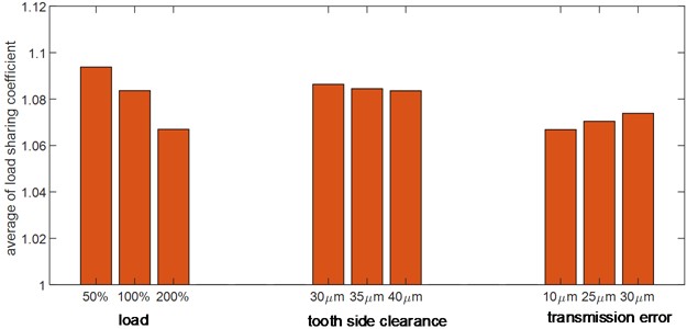
Fig. 16 presents load sharing coefficient under the influence of each system parameter. It is evident that load has the greatest impact on load sharing coefficient: higher loads correlate with smaller coefficients, indicative of better equalization effects. Tooth side clearance minimally impacts on load sharing coefficient, whereas transmission error significantly impacts: an increase in transmission error amplifies the load sharing coefficient, worsening the load equalization effects.
Fig. 16Average values of load sharing coefficient under the influence of each system parameter
6. Conclusions
This study develops a nonlinear time-varying model using the finite element nodal method, and provides a comprehensive analysis of the impact of load and system parameters on meshing force, system kinetic energy, strain energy, and the load sharing coefficient of the planetary gear system, The study draws the following key conclusions:
1) Unbalanced vibration in the planetary gear system exacerbates the collision between gear teeth and increases the amplitude of the gear meshing force. By analyzing the side-band frequency intervals, the mechanism of the unbalance-induced meshing side-band modulation is revealed. The appearance and amplitude of the sideband frequency are related to the gear collision. As the gear collision intensifies, the amplitude of the sideband frequency increases.
2) When the sum of the internal and external excitations on a pair of meshing gears exceeds the tooth pressure required to maintain meshing, the gears may disengage, resulting in impacts between the teeth during the meshing process. Increasing the load or reducing the transmission error can mitigate these impacts. In the case of unilateral impacts during gear meshing, when the tooth side clearance is reduced below a certain threshold, the unilateral collision between the gear teeth will be transformed into a bilateral collision, leading to a significant increase in the peak value of the sideband frequency.
3) The distribution of kinetic energy is significantly influenced by tooth side clearance. transmission error, and load torque. Increasing the tooth side clearance can reduce kinetic energy fluctuations and improve system stability. In contrast, transmission error has a relatively minor impact on kinetic energy. Although changes in tooth side clearance a limited effect on strain energy, increased transmission error and load torque significantly elevate both the amplitude and fluctuation of strain energy, thereby affecting system longevity and stability.
4) The influence of tooth side clearance on the load sharing coefficient is relatively minor. Although an increase in tooth side clearance may slightly reduce load sharing coefficient, this effect is not substantial. In conversely, transmission error has a pronounced impact on load equalization, with higher transmission errors exacerbating fluctuations in the load sharing coefficient. Load torque has the most significant effect on load sharing coefficient; increasing load torque can significantly improve the load sharing coefficient of the system.
References
-
H. Xu, H. Ren, and D. Qin, “Dynamic characteristics of the planetary gear system with rolling bearing,” Multibody System Dynamics, Vol. 59, No. 2, pp. 171–191, Apr. 2023, https://doi.org/10.1007/s11044-023-09905-9
-
T. Jianjun et al., “Dynamic modeling and analysis of planetary gear train system considering structural flexibility and dynamic multi-teeth mesh process,” Mechanism and Machine Theory, Vol. 186, p. 105348, Aug. 2023, https://doi.org/10.1016/j.mechmachtheory.2023.105348
-
S. Wang and R. Zhu, “Nonlinear dynamic analysis of GTF gearbox,” Vibroengineering Procedia, Vol. 32, pp. 111–116, Jun. 2020, https://doi.org/10.21595/vp.2020.21475
-
K. Zhang, T. Zhou, Y. Shao, and G. Wang, “The influence of time-varying mesh stiffness on natural characteristics of planetary gear system,” in Journal of Physics: Conference Series, Vol. 1948, No. 1, p. 012079, Jun. 2021, https://doi.org/10.1088/1742-6596/1948/1/012079
-
S. Wang and R. Zhu, “Theoretical investigation of the improved nonlinear dynamic model for star gearing system in GTF gearbox based on dynamic meshing parameters,” Mechanism and Machine Theory, Vol. 156, p. 104108, Feb. 2021, https://doi.org/10.1016/j.mechmachtheory.2020.104108
-
C. Wang, “The effect of planetary gear/star gear on the transmission efficiency of closed differential double helical gear train,” Proceedings of the Institution of Mechanical Engineers, Part C: Journal of Mechanical Engineering Science, Vol. 234, No. 21, pp. 4215–4223, May 2020, https://doi.org/10.1177/0954406220921205
-
L. Zhu, R. Zhang, and C. Zou, “Research on vibration characteristics of gear-coupled multi-shaft rotor-bearing systems under the excitation of unbalance,” Journal of Vibroengineering, Vol. 19, No. 6, pp. 4070–4082, Sep. 2017, https://doi.org/10.21595/jve.2017.18141
-
J. Yang, R. Zhu, Y. Yue, G. Dai, and X. Yin, “Nonlinear analysis of herringbone gear rotor system based on the surface waviness excitation of journal bearing,” Journal of the Brazilian Society of Mechanical Sciences and Engineering, Vol. 44, No. 2, Jan. 2022, https://doi.org/10.1007/s40430-021-03352-3
-
Z. Haoran, W. Sanmin, C. Peng, L. Bo, R. Hongfei, and L. Linlin, “Influence of gear modification on dynamic characteristics of star gearing system in geared turbofan (GTF) gearbox based on a closed-loop dynamic analysis method,” Proceedings of the Institution of Mechanical Engineers, Part E: Journal of Process Mechanical Engineering, Apr. 2024, https://doi.org/10.1177/09544089241239589
-
A. Tatar, C. W. Schwingshackl, and M. I. Friswell, “Dynamic behaviour of three-dimensional planetary geared rotor systems,” Mechanism and Machine Theory, Vol. 134, pp. 39–56, Apr. 2019, https://doi.org/10.1016/j.mechmachtheory.2018.12.023
-
H. Dong, Z.-Y. Liu, X.-L. Zhao, and Y.-H. Hu, “Research on static load sharing characteristics of power split two-stage five-branching star gearing drive system,” Journal of Vibroengineering, Vol. 21, No. 1, pp. 11–27, Feb. 2019, https://doi.org/10.21595/jve.2018.19450
-
S. Wang and R. Zhu, “Nonlinear dynamic analysis of GTF gearbox under friction excitation with vibration characteristics recognition and control in frequency domain,” Mechanical Systems and Signal Processing, Vol. 151, p. 107373, Apr. 2021, https://doi.org/10.1016/j.ymssp.2020.107373
-
S. Mo, Y. Zhang, Q. Wu, H. Houjoh, and S. Matsumura, “Research on natural characteristics of double-helical star gearing system for GTF aero-engine,” Mechanism and Machine Theory, Vol. 106, pp. 166–189, Dec. 2016, https://doi.org/10.1016/j.mechmachtheory.2016.09.001
-
F. Guo, Z. Fang, X. Zhang, and Y. Cui, “Influence of the eccentric error of star gear on the bifurcation properties of herringbone star gear transmission with floating sun gear,” Shock and Vibration, Vol. 2018, No. 1, p. 60145, Jan. 2018, https://doi.org/10.1155/2018/6014570
-
H. Zou, S. Wang, P. Chen, J. Ge, and L. Liu, “Global dynamic characteristics analysis of GTF star gear transmission system considering ring gear elastic deformation,” Thin-Walled Structures, Vol. 198, p. 111712, May 2024, https://doi.org/10.1016/j.tws.2024.111712
-
W. Liu, Z. Shuai, Y. Guo, and D. Wang, “Modal properties of a two-stage planetary gear system with sliding friction and elastic continuum ring gear,” Mechanism and Machine Theory, Vol. 135, pp. 251–270, May 2019, https://doi.org/10.1016/j.mechmachtheory.2019.01.026
-
D. Li, S. Wang, D. Li, and Y. Yang, “Efficiency analysis of herringbone star gear train transmission with different load-sharing conditions,” Applied Sciences, Vol. 12, No. 12, p. 5970, Jun. 2022, https://doi.org/10.3390/app12125970
-
L. Ryali and D. Talbot, “Dynamic load distribution of planetary gear sets subject to both internal and external excitations,” Forschung im Ingenieurwesen, Vol. 86, No. 3, pp. 283–294, Jul. 2021, https://doi.org/10.1007/s10010-021-00506-6
-
H. Zhang, S. Li, and X. Zhang, “Dynamics model and vibrational response analysis of helical gear-rotor-bearing transmission system,” Journal of Vibroengineering, Vol. 26, No. 2, pp. 240–263, Mar. 2024, https://doi.org/10.21595/jve.2023.23371
-
L. Hou and S. Cao, “Nonlinear dynamic analysis on planetary gears-rotor system in geared turbofan engines,” International Journal of Bifurcation and Chaos, Vol. 29, No. 6, p. 1950076, Jun. 2019, https://doi.org/10.1142/s0218127419500767
-
J. Wang, S. Yang, Y. Liu, and R. Mo, “Analysis of load-sharing behavior of the multistage planetary gear train used in wind generators: effects of random wind load,” Applied Sciences, Vol. 9, No. 24, p. 5501, Dec. 2019, https://doi.org/10.3390/app9245501
-
Y. Huangfu, X. Dong, Y. Cao, Z. Li, Z. Peng, and Y. Sun, “A life-cycle dynamic wear degradation model of planetary gear systems,” Wear, Vol. 542-543, p. 205281, Apr. 2024, https://doi.org/10.1016/j.wear.2024.205281
-
D. Gao and Z. Gao, “Nonlinear dynamic characterization of sliding bearing-planetary gear system,” Journal of the Brazilian Society of Mechanical Sciences and Engineering, Vol. 47, No. 1, Dec. 2024, https://doi.org/10.1007/s40430-024-05295-x
-
S. Li, R. Pang, and J. Liu, “Influence of the position error of planetary gear on the vibrations of a planetary gear system,” International Journal of Powertrains, Vol. 12, No. 2, pp. 149–163, Jan. 2023, https://doi.org/10.1504/ijpt.2023.131558
-
C. Dong, L. Li, Y. Liu, and Y. Wei, “Translation torsion coupling dynamic modeling and nonlinearities investigation of non-circular planetary gear systems,” Nonlinear Dynamics, Vol. 112, No. 21, pp. 18931–18948, Jul. 2024, https://doi.org/10.1007/s11071-024-10004-3
-
S. Zhou, G. Song, Z. Ren, and B. Wen, “Nonlinear dynamic analysis of coupled gear-rotor-bearing system with the effect of internal and external excitations,” Chinese Journal of Mechanical Engineering, Vol. 29, No. 2, pp. 281–292, Dec. 2015, https://doi.org/10.3901/cjme.2015.1019.124
-
E. Brassitos and N. Jalili, “Dynamics of integrated planetary geared bearings,” Journal of Vibration and Control, Vol. 26, No. 7-8, pp. 565–580, Jan. 2020, https://doi.org/10.1177/1077546319889848
-
J. Liu, H. Zhang, J. Zhai, and Q. Han, “Research on nonlinear dynamic performance of the central bevel gear transmission system in aero-engine with complex excitation,” Mechanics Based Design of Structures and Machines, Vol. 51, No. 12, pp. 6680–6703, Dec. 2023, https://doi.org/10.1080/15397734.2022.2054821
-
L. Xiang, Z. Deng, and A. Hu, “Dynamical analysis of planetary gear transmission system under support stiffness effects,” International Journal of Bifurcation and Chaos, Vol. 30, No. 6, p. 2050080, Jun. 2020, https://doi.org/10.1142/s0218127420500807
-
Z. Liu, F. Li, and B. Jing, “Coupled vibration analysis of a bevel geared rotor-bearing system,” Smart Innovation, Systems and Technologies, Vol. 166, pp. 233–249, Aug. 2020, https://doi.org/10.1007/978-3-030-57745-2_20
-
H. Tian, H. Wang, X. Zhao, and H. Ma, “Dynamic modeling of GTF star gear-rotor coupling system considering structural flexibility,” Journal of Sound and Vibration, Vol. 560, p. 117813, Sep. 2023, https://doi.org/10.1016/j.jsv.2023.117813
About this article

This research project is supported by the Aeronautical Science Foundation of China (No. 2022Z042063001), the 2024 Fundamental Research Project of the Educational Department of Liaoning Province (No. LJ212410154038) and Natural Science Foundation of Liaoning Province (2023-MS-301).
The datasets generated during and/or analyzed during the current study are available from the corresponding author on reasonable request.
Hao Zhang: conceptualization. Peng Zhao: methodology. Jingyu Zhai: supervision. Qingkai Han: project administration.
The authors declare that they have no conflict of interest.
