Abstract
There is a growing interest in the area of human – robot interactions as the human – robot interactions plays an important role in the control design for the robot. The paper proposes a feedback torque control for a three degree of freedom model of an arm exoskeleton used for assisting user movement. Base on controlling the interaction torques in three joints of the robot to track the desired interaction torques, the feedback torque control is carried out to shape the impedance of the device. The optimal feedback torque control is carried out to minimize the total root mean square of human – robot interaction torques at three joints by using the Balancing Composite Motion Optimization.
Highlights
- The optimal control is carried out to minimize the interaction torque by BCMO.
- The dimension of the optimal problem is six including the proportional gains and the virtual coefficients.
- The so-called feedback torque controller can track the desired torques generated by the virtual coefficients.
- The fluctuations from outside environment are included in the control model besides the interaction torques.
- The interaction torque model includes rotational spring and translational spring.
1. Introduction
The arm exoskeleton is an arm-like robot consisting of links and joints that can be worn on the user’s arm. The arm exoskeleton is powered by electric motors mounted at the joints of the exoskeleton. The exoskeleton research centers in the world today are more interested in controlling the interaction force between the human and exoskeletons. When designing the control of the exoskeleton, they always describe the interaction force between the user and the exoskeleton as the key for the control design. The force control methods which use one force sensor at least to measure the interaction force include:
a) Feedback velocity control, which includes a force sensor (loadcell), in addition to using a velocity sensor, and a position sensor to control an arm exoskeleton to move at the desired velocity and to desired position based on the measured interaction forces. The purpose of the feedback velocity control is to create a desired impedance and/or admittance for the device, helping to reduce the interaction force between the user and the arm exoskeleton when moving (M. Parnichkun et al. [1]).
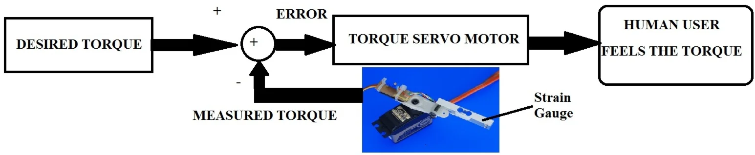
b) The feedback force control, which can initially generate desired interaction force and then guides the interaction force to track the desired one. It is called the feedback force control and can be applied to control the desired impedance and/or admittance of the device (J. Tang et al. [2], T.C. Nguyen et. al [3]-[5], L. T. H. Gam et al. [6], Kim S. et al. [7]).
The advantage of the feedback force and feedback velocity control is that they use force sensors to measure the interaction force. However, they are very sensitive to all interaction forces including human-machine interaction forces and fluctuations from the external environment. Therefore, scientists have developed controls that do not use any force sensors. Instead, they can use EMG sensors to measure bioelectric signal (BES) in the human arm, or encoders to measure angular velocities. The force control methods which do not use any force sensor to measure the interaction force include:
a) Disturbance observer control that does not use loadcell force sensors but only uses velocity sensors to estimate the interaction force and the user's movement intention as in the BLEEX project [8], to control appropriate impedance for the arm exoskeleton as in M. Parnichkun et al. [9] or in HAL of Cebernetics [10].
b) Fictitious gain control is a force control type that does not use loadcell force sensors, but only uses sensors attached to the skin where the electrical signals on the human body can be measured. Every time the human operator exerts force; EMG type sensors can measure BES [11].
The designs of the arm exoskeleton can be applied to support users with arm paralysis after a stroke to help restore arm function early [11], [12]. Applications of exoskeletons are applied in the fields of industry, defense, and aerospace [13], [14].
The interaction forces are considered as external disturbances affecting the control system and the quality of feedback force control. However, if we still want to apply feedback force control, we can use the adaptive feedback force control algorithms which can be able to adapt well to changes in the fluctuating working environment, increase sustainability and thus increase the quality of control. Or we can optimize the controller to ensure the quality against the commonly encountered noise signals of velocity or force by using the H-infinity sustainable control algorithm to limit the sensitivity of the controller [1]. The interaction force between the user and the arm exoskeleton is modeled by the spring model and is controlled by the direct force control based on adaptive fuzzy PID control [2]. The feedback force controller applies adaptive PID control based on the Model Reference Adaptive Control (MRAC) in Vu Minh Hung et al. [15].
The paper proposes the optimal feedback torque control by minimizing the interaction torque between the human user and the exoskeleton which includes the external fluctuations. The cost function of the control is defined as a total mean square of the interaction torques in three joints of the exoskeleton. To minimize the cost function, a balancing and harmonic meta heuristic optimization called Balancing Composite Motion Optimization (BCMO) is an appropriate tool to use. The BCMO brings the harmony and balance to solve the optimal values of high dimension optimizations by using the composition of high dimension movements [16]. The optimal feedback torque control is carried out to minimize the total root mean square of human – robot interaction torques at three joints by using the BCMO.
2. Arm exoskeleton design
An arm exoskeleton is modelled in Fig. 1. The arm exoskeleton has three joints including a joint at the shoulder, a joint at the elbow , and a joint at the wrist . The arm exoskeleton has three links: a shoulder link, an elbow link, and a wrist link. The vector of angles of rotation of three links 1, 2, 3 is represented by . The lengths of three links 1, 2, 3 are represented by , , , respectively. The masses of three links 1, 2, 3 are represented by , , , respectively. The feedback forces between user and the exoskeleton are , , and . The distance between the vector on the link and the center of joint is .
The Denavite-Hartenberge (D-H) table is provided in Table 1.
From the D-H table, the individual homogeneous transformation matrices are obtained by Eq. (1), [17]:
The homogeneous transformation matrix of the end effector is calculated as follows:
Fig. 1A model of a 3-DOF arm exoskeleton
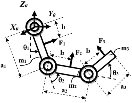
Table 1The D-H table
Link | ||||
1-1 | 0 | 0 | ||
1-2 | 0 | 0 | ||
2 | 0 | 0 | ||
3-1 | 0 | |||
3-2 | 0 | 0 | 0 |
2.1. Feedback torque control design
The dynamic equation of the arm exoskeleton is controlled by Eq. (3):
where, (rad); (rad/s); (rad/s2); (Nm) is the vector of torques exerted by the gear motors; (Nm) is the vector of torques exerted by the user, is the vector of fluctuations of outside environment or the external excitation. The details of matrices in Eq. (3) are provided in the Appendix.
The joint damping of joint is expressed as follows [18], [19]:
where, are coefficients of damping of joint .
The feedback torque control in Eq. (3) contains two phases:
Phase 1: The user actively exerts forces to guide the arm exoskeleton to follow his desired movement.
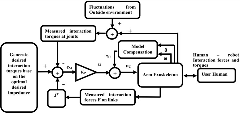
Phase 2: The arm exoskeleton is actuated to assist the user motion. In the Fig. 2, the controller controls the interaction torques at the joints to track the desired interaction torques. The controller generates the desired interaction torques at joints based on the desired impedance and control the interaction torques at joints to track their desired values to assist the user motion. Moreover, the model compensation is used to compensate and de-couple the nonlinear system.
Fig. 2Control diagram of the feedback torque control
In simulation, we model the interaction forces and torques proportionally to the misalignments between the human arm and the arm exoskeleton. The more misalignments between positions and orientations of the human arm and the arm exoskeleton occur, the more interaction forces and torques are displayed.
In phase 1, the user’s forces and torques to move the arm exoskeleton are formulated in Eq. (5) and (6), respectively. The forces and torques exerted by human are formulated more realistically by a translational and rotational spring model:
where, (N/m) is translational stiffness of spring model (1, 2, 3); (m) is the position of the user arm; (m) is the position of the exoskeleton; (N) is the user force ; is the Jacobian matrix; (Nm/rad) is rotational stiffness of spring model; ; ; ; ; , , are the desired rotations of human user joints. The details of matrices in Eq. (6) are provided in the Appendix.
In phase 2, the desired interaction torques are generated by desired impedance as follows [7]:
where, , , are virtual coefficients; (Nm) is the gravitational torque at the joint (1, 2, 3).
The errors between desired torques and measured torques are defined as follows:
where, is the measured feedback torque at the joint (1, 2, 3).
In numerical method, the measured interaction torque at the joint is modeled by fluctuations from the outside environment and human torques as follows:
where, is the measured external excitation from outside environment; is the measured torques exerted by human user at joint ; , are the coefficients of (Nm); (Nm); (1, 2, 3), respectively.
The feedback torque control is proposed as follows:
where, is the diagonal gain matrix:
Computed torque control technique is applied in feedback torque control to compensate and de-couple the non linear system [1], as expressed in Eq. (11). The voltage of direct current (DC) gear motor , , (1, 2, 3), are controlled following Eq. (12):
where, ; (V); ; (Nm); is the ratio of the gearbox.
The relationship between the , the output torque generated by DC gear motor , and the applied voltage (1, 2, 3), is derived as follows [20], [21]:
where, (Ω); (V/(rad/s)); ; (H); (A); (Nm/A) are shown in Table 2.
2.2. Optimal feedback torque control
The parameters of the arm exoskeleton are shown in the Table 2.
In BCMO, the cost function is defined as the total root mean square of the interaction torques at three joints by Eq. (15):
Table 2Parameters of the 3-DOF arm exoskeleton
Symbols | Descriptions | Values |
, , (m) | Link length | 0.3, 0.4, 0.2 (m) |
, , (kg) | Link mass | 0.35, 0.25, 0.15 (kg) |
, , (m) | Distance | 0.2 (m) |
, , (Nms/rad) | Viscosity damping coefficient | 0.3 (Nms/rad) |
(kg.m2) | Inertia moments of links | (kg.m2) |
(kg.m2) | Inertia moments of gear motors | (kg.m2) |
(V) | Supplied Voltage | 12 (V) (1, 2, 3) |
(N/m) | Translational stiffness | (N/m) (1, 2, 3) |
(Nm/rad) | Rotational stiffness | (Nm/rad) (1, 2, 3) |
(Nm/A) | Torque constant parameter | (Nm/A) (1, 2, 3) |
(Vs/rad) | Back electro motive force (Voltage) constant parameter | (Vs/rad) (1, 2, 3) |
(Ω) | Resistor parameter | (Ω) (1, 2, 3) |
(H) | Inductance of the armature | (H) (1, 2, 3) |
Ratio gearbox parameter | = 250 (1, 2, 3) | |
Gain matrix | is optimized by BCMO | |
, , | Virtual coefficient | (Nms/rad), (Nm/rad), are optimized by BCMO |
(Nm) | Maximum allowed torque | 12.5 (Nm) = 1250 (Ncm) (1, 2, 3) |
(Nm) | The fluctuation from outside environment | (Nm) |
, | The coefficients of the disturbance and the user’s torque | –1, –1 |
(s) | Simulation time | 20 (s) |
, , | The desired angles of the human user joints | (rad) |
, , | The desired speeds of the human user joints | (rad/s); (1, 2, 3) 0.5 (rad/s) |
The initial positions of the joints | (rad) | |
The initial speed of the joints | (rad/s) | |
(m/s2) | Gravitational acceleration | 9.81 (m/s2) |
In BCMO, the input parameters are defined as follows: 6; 50; MaxGen = 50; LB = 0; UB = 50, where, is dimension of optimization problem including the virtual coefficients , , and the gain matrix ; NP = population size; MaxGen = maximum generation; LB, UB = solution space; = cost function.
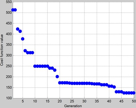
The goal of the optimal feedback torque control is minimizing the total root mean square of the human – robot interaction torques at three joints. The goal of the control can be achieved by BCMO. After 50 generations, the evolution of the cost function of BCMO is shown in Fig. 3. The virtual coefficients are obtained as ; , .
The gain matrix is obtained as
The best Cost Function = 123.75 (Ncm).
Fig. 3The evolutional progress of cost function of BCMO. Best function value: 123.7315
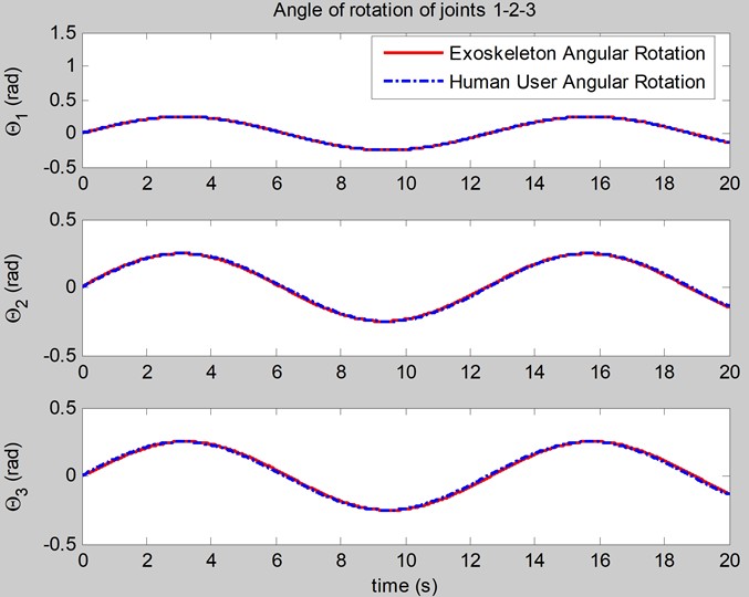
According to the BCMO results, the best cost of the feedback control system is achieved. The simulations of the rotations, angular velocities of joints of the arm exoskeleton are shown in Figs. 4, 5. The simulation of the interaction torques is shown in Fig. 6.
Fig. 4The simulation of the rotations of joints
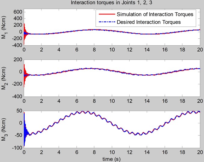
In Fig. 6, the interactions torques at joints can track the desired interaction torques, and the dynamic of the interaction torques includes the fluctuations from the outside environment. The optimal feedback torque control has been successfully carried out with the optimal impedance and/or admittance of the arm exoskeleton to support human movement; it only includes some small fluctuations in its dynamic shape.
Fig. 5The simulation of the angular velocities of joints
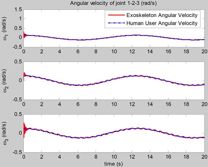
Fig. 6The simulation of the interaction torques at joints
3. Conclusions
The demand for arm exoskeletons for rehabilitation devices, haptic devices, tele-operation devices, and assisting devices is growing today. By minimizing the human – robot interaction forces as the key for the proposed control design, the optimal feedback torque control is carried out to minimize the human – robot interaction torques at joints of the three degree of freedom arm exoskeleton. The numerical simulations in the paper show that when optimal control is achieved, the total mean square of the interaction torques of the arm exoskeleton at joints is minimized; the feedback torque control can create optimal impedance for the arm exoskeleton to assist the human user movement and reducing the effect of the external excitation.
References
-
C. Silawatchananai and M. Parnichkun, “Haptics control of an arm exoskeleton for virtual reality using PSO-based fixed structure H∞ control,” International Journal of Advanced Robotic Systems, Vol. 16, No. 3, May 2019, https://doi.org/10.1177/1729881419849198
-
J. Tang, J. Zheng, and Y. Wang, “Direct force control of upper-limb exoskeleton based on fuzzy adaptive algorithm,” Journal of Vibroengineering, Vol. 20, No. 1, pp. 636–650, Feb. 2018, https://doi.org/10.21595/jve.2017.18610
-
T. C. Nguyen, M. Parnichkun, M. T. T. Phan, A. D. Nguyen, C. N. Pham, and H. N. Nguyen, “Force control of upper limb exoskeleton to support user movement,” Journal of Mechanical Engineering, Automation and Control Systems, Vol. 1, No. 2, pp. 89–101, Dec. 2020, https://doi.org/10.21595/jmeacs.2020.21689
-
T. C. Nguyen, A. D. Nguyen, M. Parnichkun, and M. T. T. Phan, “Feedback hybrid force and position control of an upper limb exoskeleton to support human movement,” Robotic Systems and Applications, Vol. 3, No. 2, pp. 84–97, Dec. 2023, https://doi.org/10.21595/rsa.2023.23623
-
T. C. Nguyen and T. N. Nguyen, “Feedback force and velocity control of an arm exoskeleton to assist user motion,” Mathematical Models in Engineering, Vol. 10, No. 1, pp. 35–48, Mar. 2024, https://doi.org/10.21595/mme.2024.23915
-
L. T. H. Gam, D. H. Quan, P. B. Ngoc, B. H. Quan, and B. T. Thanh, “Position-Force Control of a Lower-Limb Rehabilitation Robot Using a Force Feed-Forward and Compensative Gravity Proportional Derivative Method,” Electronics, Vol. 13, No. 22, p. 4494, Nov. 2024, https://doi.org/10.3390/electronics13224494
-
H. J. Lee, K.-S. Kim, and S. Kim, “Generalized Control Framework for Exoskeleton Robots by Interaction Force Feedback Control,” International Journal of Control, Automation and Systems, Vol. 19, No. 10, pp. 3419–3427, Jul. 2021, https://doi.org/10.1007/s12555-020-0097-2
-
A. Zoss, H. Kazerooni, and A. Chu, “On the mechanical design of the Berkeley Lower Extremity Exoskeleton (BLEEX),” in 2005 IEEE/RSJ International Conference on Intelligent Robots and Systems, pp. 3465–3472, Jan. 2005, https://doi.org/10.1109/iros.2005.1545453
-
C. Silawatchananai and M. Parnichkun, “Force control of an upper limb exoskeleton for virtual reality using impedance control,” in 2011 IEEE International Conference on Robotics and Biomimetics (ROBIO), pp. 2342–2347, Dec. 2011, https://doi.org/10.1109/robio.2011.6181648
-
S. Lee and Y. Sankai, “Power Assist Control For Leg With Hal-3 Based on Virtual Torque and Impedance Adjustment,” in SMC2002: IEEE International Conference on Systems, Man and Cybernetics, Vol. 4, May 2025, https://doi.org/10.1109/icsmc.2002.1173329
-
E. Guizzo and H. Goldstein, “The rise of the body bots [robotic exoskeletons],” IEEE Spectrum, Vol. 42, No. 10, pp. 50–56, Oct. 2005, https://doi.org/10.1109/mspec.2005.1515961
-
B. Dellon and Y. Matsuoka, “Prosthetics, Exoskeletons, and Rehabilitation [Grand Challenges of Robotics],” IEEE Robotics and Automation Magazine, Vol. 14, No. 1, pp. 30–34, Mar. 2007, https://doi.org/10.1109/mra.2007.339622
-
J. B. Makinson, D. P. Bodine, and B. R. Fick, “Machine augmentation of human strength and endurance Hardiman I prototype project (No. S-69-1116),” General Electric Co, Schenectady NY Specialty Materials Handling Products Operation, 1969.
-
J. Jansen, B. Richardson, F. Pin, R. Lind, and J. Birdwell, Exoskeleton for Soldier Enhancement Systems Feasibility Study. Oak Ridge, Tennessee 37831: Office of Scientific and Technical Information (OSTI), 2000, https://doi.org/10.2172/885757
-
H. M. Vu and T. Q. Trinh, “Model reference adaptive control of a haptic feedback device for improving force performance,” Science and Technology Development Journal, Vol. 17, No. 1, pp. 102–114, Mar. 2014, https://doi.org/10.32508/stdj.v17i1.1275
-
T. Le-Duc, Q.-H. Nguyen, and H. Nguyen-Xuan, “Balancing Composite Motion Optimization,” Information Sciences, Vol. 520, pp. 250–270, May 2020, https://doi.org/10.1016/j.ins.2020.02.013
-
M. W. Spong, S. Hutchinson, and M. Vidyasagar, Robot dynamics and control. Wiley, 2004.
-
T. Tjahjowidodo, F. Al-Bender, and H. van Brussel, “Friction identification and compensation in a dc motor,” in IFAC Proceedings Volumes, Vol. 38, No. 1, pp. 554–559, Jan. 2005, https://doi.org/10.3182/20050703-6-cz-1902.00093
-
H. Liu, Y.-C. Liu, M. Jin, K. Sun, and J. B. Huang, “An experimental study on Cartesian impedance control for a joint torque-based manipulator,” Advanced Robotics, Vol. 22, No. 11, pp. 1155–1180, Apr. 2012, https://doi.org/10.1163/156855308x338410
-
Sabri Centinkunt, Mechatronics. John Wiley & Sons Inc., 2007.
-
D. G. Alciatore and M. B. Histand, Introduction to mechatronics and measurement systems. New York: McGraw Hill, 2007.
About this article

The authors have not disclosed any funding.
The datasets generated during and/or analyzed during the current study are available from the corresponding author on reasonable request.
Cao Thang Nguyen: write manuscript, control design. Tuan Ngoc Nguyen: simulation.
The authors declare that they have no conflict of interest.
