Abstract
Aiming at the classical flutter problem of wind turbine blades, a wind turbine blade aeroelastic model is constructed based on the typical leaf cross-section model of spring-mass-damper and the classical flutter aerodynamic model. The stability analysis of the wind turbine aeroelastic model is carried out using the Liapunov indirect method, and the effects of different parameters on stability are compared. Combining the aeroelastic model with the second-order model of pitch exciter, the pitch aeroelastic equation of the system is given, and the system controllability is analyzed. The optimal PID pitch control is designed, and the Simulink simulation is performed to explore the optimal combination under different combinations by selecting the torsion angle and waving displacement as the error signals, and different combinations of the torsion angle, waving displacement, and pitch angle as the optimal control objectives, respectively. The simulation results show that when the torsional angle is used as the error feedback signal and the torsional angle is set as the optimal control objective, it is the only scenario without overshoot. The overshoot in other cases ranges from 30 % to 500 %. In terms of adjustment time, this scenario also demonstrates good performance. Although it is not the fastest, the gap from the fastest is no more than 20 %. Therefore, using the torsional angle as the error feedback signal and the torsional angle as the optimal control objective is the best choice.
Highlights
- Based on the spring-mass-damper cross-sectional model and classical flutter aerodynamic model, an aeroelastic model for wind turbine blades is built. The Lyapunov indirect method analyzes the influence of different parameters on stability, providing reference data for blade optimal design.
- The pitch aeroelastic model of blade torsion and flapwise motion is presented in the form of a simulation structure diagram, enabling intuitive analysis of the control relationship between pitch angle and torsion/flapwise motions.
- In the optimal PID control strategy, taking the torsional angle as the error feedback signal and the optimal control objective is the only case without overshoot, and the deviation of its adjustment time from the optimal scheme is less than 20%.
1. Introduction
During the operation of wind turbines, the blades, as critical components directly interacting with airflow to convert energy, are subjected to extremely complex loads. Strong coupling effects among aerodynamic forces, elastic forces, and inertial forces often lead to aeroelastic issues [1], [2]. Among these, flutter – a typical aeroelastic instability phenomenon – poses a severe threat to the structural integrity and stable operation of blades [3]. During flutter, self-excited oscillations are induced in the blades under airflow excitation. These oscillations exhibit large amplitudes and divergent characteristics, significantly increasing the risk of blade fracture or damage [4]. In large horizontal-axis wind turbines, flutter becomes more prominent due to the high aspect ratio and lightweight structure of the blades [5], [6]. Classical flutter, a major form of flutter, typically occurs under low angles of attack with attached airflow and no significant flow separation. Under such conditions, the flapping and torsional degrees of freedom of the blade become coupled, triggering self-excited oscillations that severely compromise the stability and safety of wind turbines [7], [8].
In aeroelastic modeling, Stäblein et al. investigated the impact of flapping-torsion coupling on the modal characteristics and stability limits of two-dimensional blade sections in attached flow using the Theodorsen model [9]. Boutet et al. proposed a modified B-L model to predict aerodynamic load responses of airfoils under low Reynolds and Mach numbers [10]. Gao Qiang et al. studied key parameters affecting classical flutter speed in wind turbine blades using the NREL-5MW turbine, establishing an aeroelastic flutter model that couples aerodynamic and structural dynamic models [11]. Liu Tingrui applied an improved model based on fitted aeroelastic coefficients to composite blade structures using simplified offset theory, analyzing stall-induced aeroelastic behavior [12]. Li Nailu et al. Introduced a B-L unsteady aerodynamic model into a scalarized flapping-torsion vibration framework to investigate classical flutter stability in rotating blades under dynamic time-varying conditions [13].
In vibration control, Yuan et al. developed a multivariable robust independent pitch control framework with explicit modeling of blade coupling to provide frequency-domain response characteristics, employing a structured singular value μ-synthesis strategy to reduce periodic loads [14]. Chen Linjun et al. Designed a real-time feedback pitch control system based on instantaneous flow velocity around the blade, evaluating its effectiveness in enhancing blade performance through aerodynamic analysis of pitch angle relationships [15]. Zhou Feihang explored individual pitch control schemes, including blade damping control, LQG control, H∞ control, and improved LQG control with optimal disturbance observers, detailing controller design processes and validating the algorithms via simulations [16].
This study investigates the aeroelastic coupling mechanisms and flutter initiation conditions in wind turbine blades, aiming to explore effective flutter suppression methods and optimal PID control strategy. The findings provide theoretical support for optimizing blade design, ensuring stable turbine operation, and enhancing the economic and social benefits of wind farms.
2. Structural model and aeroelastic equations
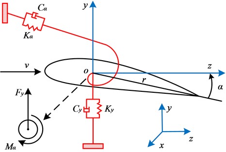
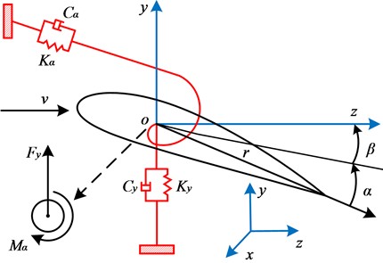
This paper investigates the stability and time-domain response characteristics of a typical blade cross-sectional model with a notably high aspect ratio. During flapping bending, and elastic torsion, this cross-sectional model (with a rotational radius denoted as ) exhibits distinct dynamic behaviors. As illustrated in Fig. 1, during the model construction, the cross-sectional mass is co-suspended by springs and dampers in both the (-axis) and (-axis) directions, where the direction corresponds to the flapping motion, and parameter denotes the torsional angle, where represents the inflow wind speed. The aerodynamic lift and corresponding moment are defined to describe the aerodynamic forces and moments acting on the blade.
Fig. 1Coordinate system and aerodynamic forces
When the pitch angle is 0, the momentum equilibrium equation is established about the elastic axis, while the force equilibrium equation is formulated considering the aerodynamic lift effects. By aggregating the mass, damping, and stiffness terms and equating them to the total force and moment generated by aerodynamic lift, the following pair of second-order ordinary differential equations is derived through the application of Lagrange’s equations of motion [17]:
where, represents the flapwise displacement, represents the flapwise velocity, and represents the flapwise acceleration; represents the torsional angle, represents the torsional velocity, and represents the torsional acceleration; and are the stiffness coefficients in the flapwise and torsional directions, respectively; and are the damping coefficients in the flapwise and torsional directions, respectively; is the static moment of the elastic axis, is the mass moment of inertia in the torsional direction, and is the total linear mass of the section. and represent the normalized natural frequencies in the flapwise and torsional directions, respectively; and represent their corresponding damping ratios; and is the angular velocity.Since the classical flutter of the blade occurs in the linear flow region where airflow does not separate from the airfoil surface, it can be analyzed under the action of steady aerodynamic forces. The aerodynamic lift and moment of the blade are described using a linear aerodynamic model, expressed as:
where represents the air density, represents the chord length, represents the slope of the lift coefficient with respect to the torsion angle, considered constant with a value equal to , and represents the chord fraction, with a value of -0.15.
In the present study, the aeroelastic stability analysis actually solves a completely linear flutter problem, as described in reference [17]. Under the same normalization scheme in this simplified classic flutter problem, the aerodynamic lift and moment belong to a proportional relationship of constant coefficient, as implied by Eq. (2), which can be expressed as: . Therefore, the static moment of the elastic axis exhibits the same coefficient in both flapwise and torsional directions. By combining Eq. (1) with (2), the aeroelastic equation of the blade's flapwise-torsional motion can be expressed as:
where, represents the reduction factor, and represents the ratio of air density to sectional linear density.
3. Aerodynamic elastic stability analysis of blades
This section establishes a state-space model (Eq. (6)) based on the second-order ordinary differential equations (Eq. (3)), analyzes system stability using Lyapunov’s indirect method, and reveals the influence mechanisms of reduced wind speed, mass ratio, damping ratio, and natural frequency on flutter characteristics through parametric studies.
Let , , , . Then, the Eq. (3) can be rewritten as:
Translate the above equations into the general form of state-space representation:
where:
According to Lyapunov’s indirect method, internal stability reveals the stability of the internal state’s free motion when the system has zero input. For the linear time-invariant system described by Eq. (6), the necessary and sufficient condition for asymptotic stability is that all eigenvalues of matrix have negative real parts, i.e.:
To further investigate the factors influencing the aeroelastic stability of the blade, a study based on the classical flutter analysis of the NACA0015 airfoil from reference [17] is conducted using dimensionless parameters. The natural frequency in the flapping direction is set to 4 with a damping ratio of 0.02, while the natural frequency in the torsional direction is set to 7 with a damping ratio of 0.01. The effects of the reduced frequency and the ratio of air density to linear density on the blade’s aeroelastic stability are explored, as shown in Fig. 2.
The reduced frequency reflects changes in wind speed, while the ratio directly influences the blade’s unit mass. By systematically adjusting these two parameters, a comprehensive understanding of their impact on the blade’s aeroelastic stability can be achieved.
Fig. 2Maximum eigenvalue variation for different k and Rf
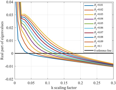
The results indicate that the aeroelastic stability of the blade exhibits significant variations under different values of and . Specifically, as increases (indicating a decrease in wind speed), the flutter phenomenon is effectively suppressed. Changes in also have a notable impact on the blade's aeroelastic stability. When is relatively small, the blade’s unit mass is larger, resulting in greater relative stability. However, as increases, the blade’s unit mass decreases (lighter blades), leading to a corresponding increase in the risk of flutter.
Further investigation was conducted to explore the influence of damping ratios in the torsional direction () and flapping direction () on the aeroelastic stability of the blade. The reduced frequency was set to 0.13, and the ratio of air density to linear density was set to 0.08. During the simulation, and were held constant, while the values of and were adjusted separately. The eigenvalues of the blade under different damping ratios were calculated, as shown in Fig. 3.
Fig. 3Variation of maximum eigenvalue for different ξα and ξy
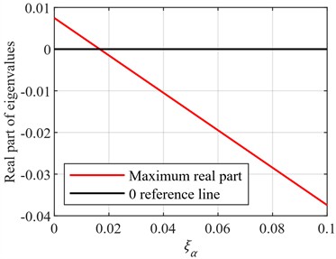
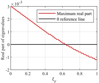
During the simulation, the damping ratios in both the torsional () and flapwise () directions were increased, and their effects on stability were observed. The results demonstrate that increasing the damping ratios effectively suppresses blade vibrations, thereby enhancing its aeroelastic stability. Notably, increasing the damping ratio in the torsional direction generally yields better results compared to the flapping direction. This is because torsional vibrations tend to have a more direct and significant impact on the blade’s stability. By increasing the torsional damping ratio, the amplitude of vibrations induced by aerodynamic moments can be more effectively reduced, allowing the blade to return to equilibrium more quickly. Therefore, in the design and optimization of blades, it is essential to consider the damping ratios in both directions comprehensively and make appropriate adjustments based on practical conditions.
Fig. 4Variation of maximum eigenvalue for different ωα and ωy
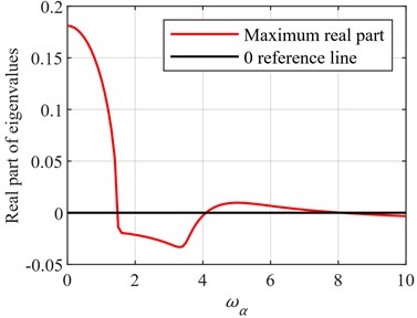
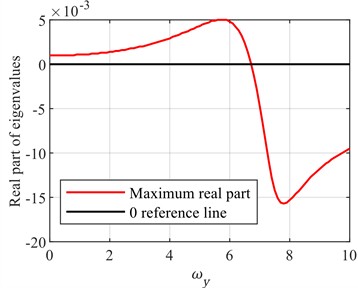
In the process of investigating the aeroelastic stability of the blade, the effects of the natural frequencies in the flapping direction () and torsional direction () on stability were analyzed. The natural frequencies are critical indicators of the blade's structural characteristics, determining its vibrational behavior under external excitation. During the calculations, other parameters were held constant, while the values of and were adjusted independently. The eigenvalues of the blade under different natural frequencies were observed, as shown in Fig. 4. The results indicate that altering the blade's natural frequencies can influence its vibrational stability, but this relationship is not simply linear.
Specifically, when the natural frequency increases to a certain level, the vibration stability of the blade may improve. This is because a higher natural frequency implies that the blade generates smaller vibration amplitudes under the same excitation and can return to the equilibrium state more quickly. However, when the natural frequency continues to increase, it may trigger other forms of vibration instability, such as resonance phenomena, which can instead reduce the overall stability of the blade.
Therefore, in the process of blade design and optimization, it is not sufficient to simply increase or decrease the natural frequency to improve stability. It is necessary to comprehensively consider the effects of various parameters and conduct systematic analysis and optimization. This is of great significance for ensuring the safe and stable operation of the blade in various complex environments.
4. Blade pitch aerodynamic model and controllability analysis
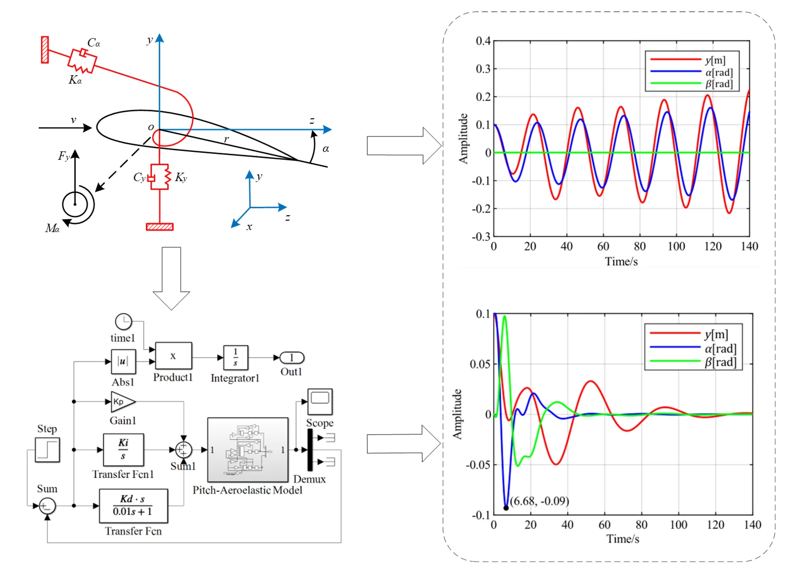
In previous studies on pitch control, the primary focus of pitch adjustment has been to alter the angle of attack of the airflow on the blade, maximizing the wind-facing area to enhance power generation efficiency [18]-[20]. In this study, however, the wind turbine blade system utilizes pitch motion to avoid the maximum wind-facing area, serving as a protective measure for the blade. Under no-pitch conditions, the angle of attack equals the torsional angle . When pitch motion is introduced, the angle of attack becomes the sum of the torsional angle and the pitch angle , as illustrated in Fig. 5.
Fig. 5Blade cross-section model incorporating pitch angle
To validate the impact of the pitch angle on the aeroelastic stability of the blade, a second-order pitch actuator model is designed in this study as described in reference [21]:
where, represents the controller's requested pitch angle, which is the input of the pitch angle in the control system. The values are set as 0.2, 1.1, 1, and in the dimensionless form 5 and 0.02. By combining Eq. (3) with Eq. (8), the aeroelastic motion equation of the blade’s flapwise-torsional-pitch motion can be expressed as:
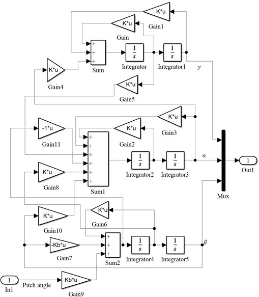
This model can simulate the dynamic response of the blade during the pitching process, thereby revealing the mechanism of pitch angle variation on blade stability. By transforming the above aeroelastic equation into a simulation structure diagram, as shown in Fig. 6, it can be observed that the flapwise displacement can be altered by inputting the pitch angle , indicating that the state variable is controllable. Similarly, the torsional angle can also be modified by changing the pitch angle, meaning the state variable is controllable as well. Therefore, all states of this system are controllable, i.e., the system is fully controllable. Consequently, blade flutter suppression can be achieved by adjusting the pitch angle .
Fig. 6Pitch air bomb model simulation structure
5. Research on optimal PID pitch control
Optimal PID control is based on traditional PID control, where an objective function is constructed to maximize or minimize the response of the controlled object. Specifically, when designing the objective function, the ITAE criterion is adopted, and the objective function is selected as , where is the error signal. The control objective is to minimize the value of the objective function, indicating better control performance [22]. In optimal PID control, by incorporating the objective function into the error signal, the best control results are achieved under global optimal search conditions. This approach can provide more stable and precise control effects in various complex environments and operating conditions, which is of great significance for improving the performance and reliability of wind power generation systems. In practical applications, optimal PID control usually requires design and optimization based on specific control objects and environmental conditions to ensure the best control performance.
Fig. 7Block diagram of optimal PID pitch control system
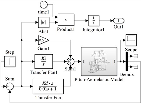
In the vibration control of wind turbines, selecting appropriate error signals and optimal control objective functions is crucial for achieving effective vibration suppression and improving system performance. Since the input parameter is the pitch angle, and the output states include the torsional angle and flapwise displacement, it is necessary to study the roles of these states in the control system. By considering different combinations of torsional angle, flapwise displacement, and pitch angle as optimal control objectives, the control effects under various combinations can be explored through Simulink simulations. The Simulink block diagram of the optimal PID pitch control system is shown in Fig. 7, where the torsional angle serves as the feedback error By selecting suitable error signals and optimal control objective functions, as well as conducting Simulink simulation analysis, the optimal control strategies under different combinations can be effectively investigated, providing strong support for the vibration control of wind turbines. This will contribute to enhancing the stability, reliability, and economic efficiency of wind power systems.
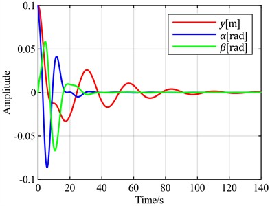
Fig. 8v = 20 m/s and v = 5 m/s blade vibration time domain response
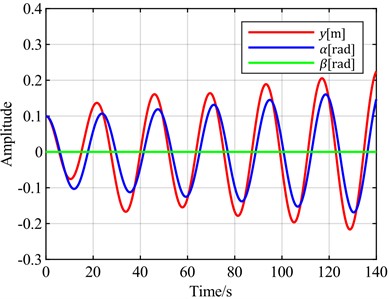
a) = 20 m/s
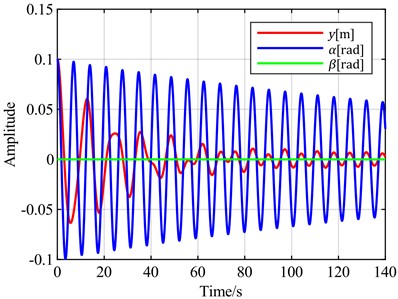
b) = 5 m/s
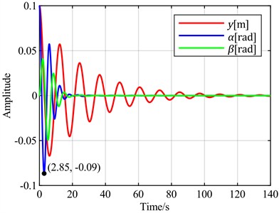
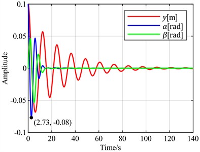
First, the initial state is given with a flapwise displacement of 0.1 m, a torsional angle of 0.1 rad, and a pitch angle of . A wind speed of 20 m/s is selected for flutter analysis. According to the stability analysis results, the blade is in a divergent flutter state at this time. The time-domain response curve without pitch control is shown in Fig. 8(a). The torsional angle is set as the feedback error signal. The time-domain response curves for different combinations of torsional angle, flapwise displacement, and pitch angle as optimal control objectives are shown in Fig. 9.
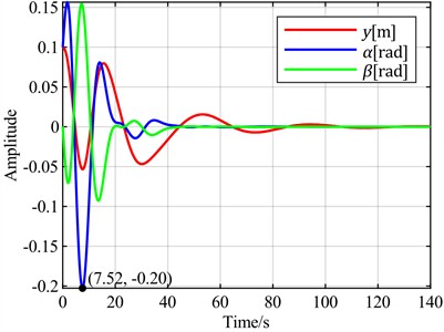
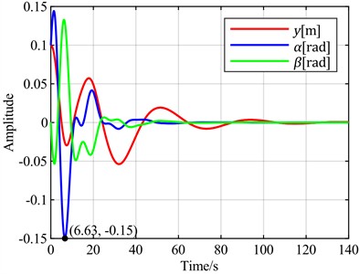
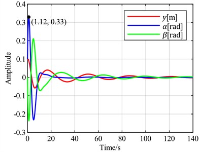
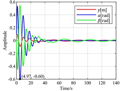
Fig. 9Time-domain responses of pitch control with different optimal objectives under feedback error α at v = 20 m/s
a)is the optimal objective
b)is the optimal objective
c) is the optimal objective
d) is the optimal objective
e) is the optimal objective
f) is the optimal objective
It can be observed that when the torsion angle is used as the control objective, there is no overshoot, resulting in the best control performance regarding signal overshoot. In contrast, all other cases exhibit overshoots ranging from 30 % to 100 %. In terms of adjustment time, when the torsion angle is the control objective, it takes 44 seconds for the torsion to converge to a steady state. The fastest torsion convergence occurs at 37 seconds, achieved when the control objective is minimizing the sum of the torsion angle and pitch angle. The slowest convergence, requiring 70 seconds, is observed when the flap displacement is used as the control objective. When the torsion angle is the control objective, the flap displacement takes 120 seconds to converge to a steady state, which is the slowest among all scenarios, while other cases range between 100 and 102 seconds.
Fig. 10Time-domain responses of pitch control with different optimal objectives under feedback error y at v = 20 m/s
a) is the optimal objective
b) is the optimal objective
c) is the optimal objective
d) is the optimal objective
e) is the optimal objective
f) is the optimal objective
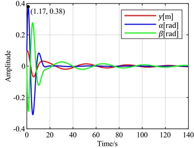
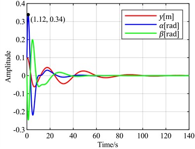
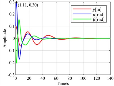
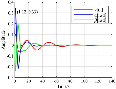
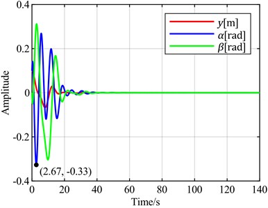
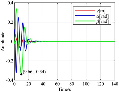
Next, the flapwise displacement is set as the feedback error signal. The time-domain response curves for different combinations of torsional angle, flapwise displacement, and pitch angle as optimal control objectives are observed through simulation, as shown in Fig. 10.
Fig. 11Time-domain responses of pitch control with different optimal objectives under feedback error α at v = 5 m/s
a) is the optimal objective
b) is the optimal objective
c) is the optimal objective
d) is the optimal objective
e) is the optimal objective
f) is the optimal objective
It can be observed that using the flapwise displacement as the feedback error, under different optimal objectives, the adjustment times for torsion and flapwise show little difference from the case where the torsion angle is used. However, the torsion angles all exhibit overshoots ranging from 200 % to 500 %. Notably, the overshoot is minimized when the optimal objective is set as the sum of the flapwise displacement and pitch angle. Therefore, when the flapwise displacement is employed as the feedback error, a distinct characteristic emerges: a significant overshoot magnitude.
Fig. 12Time-domain responses of pitch control with different optimal objectives under feedback error y at v = 5 m/s

a)is the optimal objective
b)is the optimal objective
c)is the optimal objective
d)is the optimal objective
e) is the optimal objective
f) is the optimal objective
To verify the universality of the above conclusions, a wind speed of 5 m/s is selected for vibration analysis. According to the stability analysis results, the blade is in a convergent state at this time. The time-domain response curve without pitch control is shown in Fig. 8(b). When the torsional angle is set as the feedback error signal, the time-domain response curves for different combinations of torsional angle, flapwise displacement, and pitch angle as optimal control objectives are shown in Fig. 11. When the flapwise displacement is set as the feedback error signal, the time-domain response curves for different combinations of torsional angle, flapwise displacement, and pitch angle as optimal control objectives are observed through simulation, as shown in Fig. 12.
It can be observed that the overall trend is consistent with the case at = 20 m/s. Notably, when the sum of the torsional angle and pitch angle is selected as the optimal control objective, it exhibits almost the same convergence speed for both torsional and flapwise motions as when only the torsional angle is used as the optimal objective. However, the convergence of the pitch angle is improved in this case.
Fig. 13v = 13 m/s and v = 8 m/s blade vibration time domain response
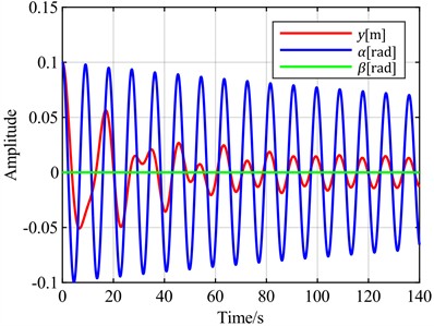
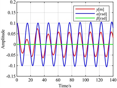
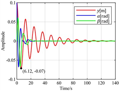
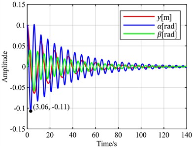
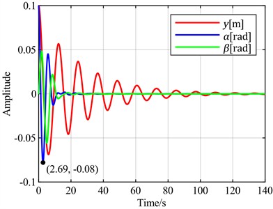
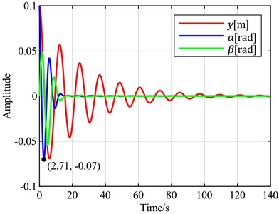
Fig. 14Time-domain responses of pitch control with different optimal objectives under feedback error α at v = 13 m/s and v = 8 m/s
a) is the optimal objective at = 13 m/s
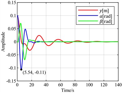
b) is the optimal objective at = 13 m/s
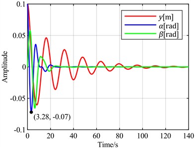
c) is the optimal objective at = 8 m/s
d) is the optimal objective at = 8 m/s
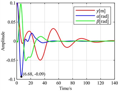
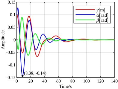
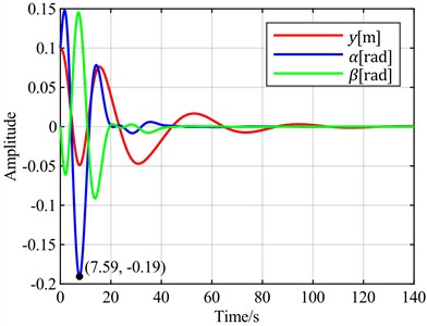
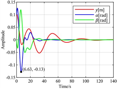
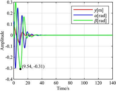
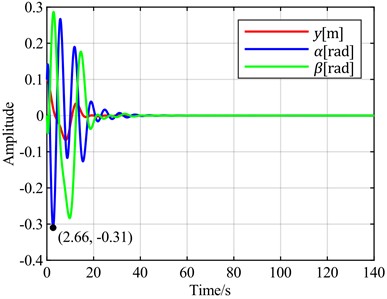
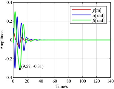
To further verify the characteristics of using the sum of the torsional angle and pitch angle as the optimal control objective compared to using only the torsional angle, the following simulation experiments were conducted. Wind speeds of 13 m/s and 8 m/s were selected for flutter analysis. At 13 m/s, the blade is in a divergent state, but the divergence speed is slow, as shown in Fig. 13(a). At 8 m/s, the blade is in a convergent state, but the convergence speed is slow, as shown in Fig. 13(b). With the torsional angle set as the feedback error signal, simulations were performed using both the torsional angle and the sum of the torsional angle and pitch angle as optimal control objectives. The simulation results are shown in Fig. 14.
Comprehensive analysis of the above simulation results shows that as wind speed increases, the increment in overshoot is significantly greater when the sum of the torsional angle and pitch angle is used as the optimal control objective compared to using only the torsional angle as the optimal control objective. When the blade is stable, neither case exhibits overshoot. However, when blade flutter occurs, overshoot appears when the sum of the torsional angle and pitch angle is used as the optimal control objective.
In addition, experimental methods related to engineering applications are also a topic that must be explored. Whether for aircraft airfoils or wind turbine blade airfoils, PID control theory is a well-established application plan in airfoil vibration control [23], and PID control has been applied in Programmable Logic Controller (PLC) hardware of wind power systems. However, the tuning of PID parameters in this article is based on optimization theory, which is difficult to directly apply in PLC controller systems. Reference [23] precisely proposed a Refined OPC (Object-Linking-and-Embedding for Process Control) Technology (ROT) to solve this problem. After the optimization method is executed in MATLAB environment, the PID parameters have been determined. Due to the stability of the system, optimization theory does not need to run every time the system starts. The set of PID parameters only needs to be directly written into the PLC’s memory once, thus departing from optimization theory in future PID program execution.
Fig. 15The ROT method and the time-domain responses of pitch control illustrated in KingView
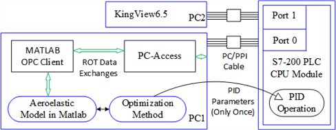
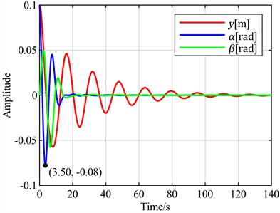
a) The ROT method in the present study
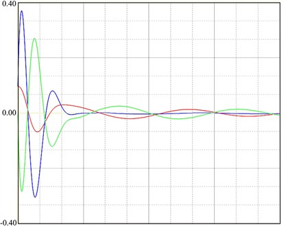
b) The experimental responses of pitch control based on Fig. 10(c)
Based on the ROT method, the PLC hardware starts the built-in PID operation module and exchanges data with the MATLAB environment through OPC communication, while the governing Eq. (10) is still constructed in the MATLAB environment. This can build a semi-physical simulation platform experiment to approximately verify the engineering application planning. Based on analysis [23], Fig. 15(a) demonstrates the ROT method in the present study. The ROT plan is basically consistent with literature [23], except that the human-machine interface has been replaced by KingView configuration software. Taking the case in Fig. 10(c) as the research object, Fig. 15(b) shows the controlled displacement responses displayed in KingView with as the optimization objective. Comparing Fig. 10(c) and Fig. 15(b), the time responses of the three variables show considerable consistency in both the trends of change and the amplitudes of response, which also confirms the feasibility of the optimization-based PID control proposed in this problem in engineering applications.
6. Conclusions
For the multi-coupled aeroelastic system of wind turbine blades, based on the Lyapunov indirect method, the effects of different reduction factors, the ratio of air density to sectional linear density, natural frequencies in the torsional and flapwise directions, and damping ratios on blade stability were analyzed. The results indicate that the aforementioned parameters significantly influence the stability of the blade. Increasing the blade's unit mass and damping ratio can effectively suppress blade vibrations, thereby enhancing its aeroelastic stability. However, a higher natural frequency of the blade does not necessarily equate to better performance. These findings provide reference data for the optimization design direction of wind turbine blades.
The pitch aeroelastic model of blade torsional and flapwise motion was presented in the form of simulation result diagrams, allowing for an intuitive analysis of the control relationship between pitch angle and torsional/flapwise motions.
The optimal PID pitch control algorithm can achieve the purpose of suppressing blade flutter. Selecting different feedback error signals and optimization objectives has a significant impact on the flutter suppression process. When the torsion angle is used as the error feedback signal and the torsion angle is taken as the optimal control objective, it is the only case without overshoot, while other cases all have 30 %-100 % overshoot. When the flapwise displacement is used as the feedback error, the torsion angles under different optimal objectives all have 200 %-500 % overshoot. In terms of adjustment time, although taking the torsion angle as the error feedback signal and the torsion angle as the optimal control objective is not the optimal, the gap from the optimal is not large, within 20 %. Therefore, taking the torsion angle as the error feedback signal and the torsion angle as the optimal control objective is the best choice.
References
-
H. Wu et al., “Research on vibration suppression effect and energy dissipation mechanism of wind turbine piezoelectric blade,” Journal of Fluids and Structures, Vol. 117, p. 103814, Feb. 2023, https://doi.org/10.1016/j.jfluidstructs.2022.103814
-
P. A. Meehan, “Prediction and suppression of chaos following flutter in wind turbines,” Nonlinear Dynamics, Vol. 111, No. 24, pp. 22153–22176, Sep. 2023, https://doi.org/10.1007/s11071-023-08841-9
-
Z. Li, S. Zhou, and Z. Yang, “Recent progress on flutter‐based wind energy harvesting,” International Journal of Mechanical System Dynamics, Vol. 2, No. 1, pp. 82–98, Apr. 2022, https://doi.org/10.1002/msd2.12035
-
H. Wang, J. Yi, W. Chen, and Z. Zhou, “Flutter analysis of piezoelectric material based smart wind turbine blade,” The International Journal of Acoustics and Vibration, Vol. 26, No. 3, pp. 240–247, Sep. 2021, https://doi.org/10.20855/ijav.2021.26.31787
-
R. Yang, W. Yang, and Z. L. Chen, “Analysis of thickness of damping layer of large wind turbine blades and study on flutter suppression,” Journal of Lanzhou University of Technology, Vol. 47, No. 4, p. 45, Sep. 2021.
-
X. Zhang et al., “Bionic inspired flutter suppression method for offshore ultra-long wind turbine blades,” Renewable Energy, Vol. 239, p. 122091, Feb. 2025, https://doi.org/10.1016/j.renene.2024.122091
-
T. Liu, “Classical flutter and active control of wind turbine blade based on piezoelectric actuation,” Shock and Vibration, Vol. 2015, No. 1, pp. 1–13, Jan. 2015, https://doi.org/10.1155/2015/292368
-
K. Hayat, A. G. M. de Lecea, C. D. Moriones, and S. K. Ha, “Flutter performance of bend-twist coupled large-scale wind turbine blades,” Journal of Sound and Vibration, Vol. 370, pp. 149–162, May 2016, https://doi.org/10.1016/j.jsv.2016.01.032
-
A. R. Stäblein, M. H. Hansen, and G. Pirrung, “Fundamental aeroelastic properties of a bend-twist coupled blade section,” Journal of Fluids and Structures, Vol. 68, pp. 72–89, Jan. 2017, https://doi.org/10.1016/j.jfluidstructs.2016.10.010
-
J. Boutet, G. Dimitriadis, and X. Amandolese, “A modified Leishman-Beddoes model for airfoil sections undergoing dynamic stall at low Reynolds numbers,” Journal of Fluids and Structures, Vol. 93, p. 102852, Feb. 2020, https://doi.org/10.1016/j.jfluidstructs.2019.102852
-
Q. Gao, X. Cai, X.-W. Guo, and R. Meng, “Parameter sensitivities analysis for classical flutter speed of a horizontal axis wind turbine blade,” Journal of Central South University, Vol. 25, No. 7, pp. 1746–1754, Jul. 2018, https://doi.org/10.1007/s11771-018-3865-x
-
T. Liu, “Vibration and aeroelastic control of wind turbine blade based on B-L aerodynamic model and LQR controller,” Journal of Vibroengineering, Vol. 19, No. 2, pp. 1074–1089, Mar. 2017, https://doi.org/10.21595/jve.2016.17230
-
N. Li, A. Mu, and M. Balas, “Classical flutter stability of rotating horizontal wind turbine blades based on B-L aeroelastic model,” Joural of Vibration and Shock, Vol. 34, No. 23, Dec. 2015, https://doi.org/10.13465/j.cnki.jvs.2015.23.030
-
Y. Yuan, X. Chen, and J. Tang, “Multivariable robust blade pitch control design to reject periodic loads on wind turbines,” Renewable Energy, Vol. 146, pp. 329–341, Feb. 2020, https://doi.org/10.1016/j.renene.2019.06.136
-
L. Chen, Y. Yang, Y. Gao, Z. Gao, Y. Guo, and L. Sun, “A novel real-time feedback pitch angle control system for vertical-axis wind turbines,” Journal of Wind Engineering and Industrial Aerodynamics, Vol. 195, p. 104023, Dec. 2019, https://doi.org/10.1016/j.jweia.2019.104023
-
F. Zhou, J. Yang, J. Pang, and B. Wang, “Research on control methods and technology for reduction of large-scale wind turbine blade vibration,” Energy Reports, Vol. 9, pp. 912–923, Dec. 2023, https://doi.org/10.1016/j.egyr.2022.12.042
-
P. K. Chaviaropoulos et al., “Viscous and aeroelastic effects on wind turbine blades. The VISCEL Project. Part II: aeroelastic stability investigations,” Wind Energy, Vol. 6, No. 4, pp. 387–403, Jul. 2003, https://doi.org/10.1002/we.101
-
T. L. Van, T. H. Nguyen, and D.-C. Lee, “Advanced pitch angle control based on fuzzy logic for variable-speed wind turbine systems,” IEEE Transactions on Energy Conversion, Vol. 30, No. 2, pp. 578–587, Jun. 2015, https://doi.org/10.1109/tec.2014.2379293
-
M. R. Sarkar, S. Julai, C. W. Tong, M. Uddin, M. F. Romlie, and G. Shafiullah, “Hybrid pitch angle controller approaches for stable wind turbine power under variable wind speed,” Energies, Vol. 13, No. 14, p. 3622, Jul. 2020, https://doi.org/10.3390/en13143622
-
A. Gambier, “Pitch control of three bladed large wind energy converters-a review,” (in English), Energies, Vol. 14, No. 23, p. 8083, Dec. 2021, https://doi.org/10.3390/en14238083
-
T. Liu, C. Sun, K. Zhao, and A. Gong, “Amplitude control of stall-induced nonlinear aeroelastic system based on iterative learning control and unified pitch motion,” Energies, Vol. 15, No. 3, p. 787, Jan. 2022, https://doi.org/10.3390/en15030787
-
D. Y. Xue, Computer Aided Control Systems Design Using MATLAB Language. Beijing, China: Tsinghua University Publishing Company, 2012.
-
T. Liu, “Vibration control and trajectory tracking for nonlinear aeroelastic system based on adaptive iterative learning control,” Noise and Vibration Worldwide, Vol. 53, No. 7-8, pp. 390–403, Jul. 2022, https://doi.org/10.1177/09574565221114659
About this article

This work was supported by the Natural Science Foundation of Shandong Provincial of China (No. ZR2022ME093).
The datasets generated during and/or analyzed during the current study are available from the corresponding author on reasonable request.
Qinghu Cui: conceptualization, formal analysis, methodology, software, writing original draft preparation, writing-review and editing. Tingrui Liu: software, validation, writing-review and editing. Deyou Ding: software, writing-review and editing.
The authors declare that they have no conflict of interest.
