Abstract
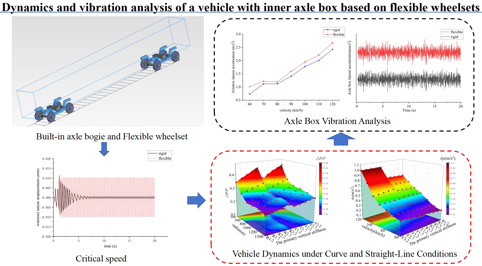
This study systematically investigates the dynamic performance and vibration characteristics of a metro vehicle equipped with an inner axle box bogie, with a focus on the effects of wheelset structural flexibility. A rigid-flexible coupled dynamics model is constructed. For computational efficiency, the flexible wheelset within it was developed using the finite element method and subsequently condensed via substructuring techniques. The model is integrated into multi-body dynamics software SIMPACK, incorporating non-linear suspension characteristics. Parametric analysis is conducted to evaluate vehicle dynamics under varying primary vertical stiffness and operating speeds, comparing rigid and flexible wheelset configurations in terms of straight-line ride comfort, non-linear critical speed, and curve negotiation safety. The influence of wheelset flexibility, evaluated through time- and frequency-domain analysis of axle-box vibration, is found to be subtle yet statistically relevant: it slightly reduces critical speed and amplifies lateral vibrations at high speeds without inducing resonance or exceeding safety thresholds. The rigid wheelset model is deemed sufficient for basic curve negotiation and vibration analysis, whereas the flexible model is recommended for critical speed and high-speed dynamics. These findings provide theoretical support for the design and optimisation of inner axle box bogies.
Highlights
- Combines an inner axle box with a flexible wheelset to carry out relevant dynamic analysis.
- Analyses the vibration effects of a flexible wheelset on the axle box.
- Due to the low anti-roll capability of the inner axle box, it is analysed together with the flexibility coefficient.
1. Introduction
Driven by the need to enhance operational efficiency and mitigate urban congestion, the development of inner axle box bogies for urban rail transit embodies a continuous pursuit of lightweight, high-performance solutions [1]. However, metro vehicles face demanding operating conditions: frequent acceleration and braking, tight geometric constraints, and continuous excitation from track irregularities. These factors collectively challenge vehicle dynamics and component durability [2]. The innovative inboard axle box configuration, while offering distinct advantages, introduces a reduction in the bogie wheelbase. It affects the moment distribution on the wheelset, thereby directly influencing the force transmission to the axle box. Alterations to the structural configuration may induce measurable effects on the operational dynamics of metro vehicles. A focused investigation into its impact on the vehicle’s critical speed, dynamic performance, and axle box vibration characteristics is therefore essential.
This design relocates the axle box assembly inward, significantly reducing unsprung mass and shortening the axle length. These changes lead to lower wheel-rail forces and improved curving performance [3-4]. However, the structural dynamics and load paths differ fundamentally from those of conventional external axle box bogies. The notably reduced lateral suspension span alters the bending moment distribution and decreases the wheelset’s anti-yaw stiffness, which may affect hunting stability [5-7]. Furthermore, as the axle box is a critical component directly subjected to wheel-rail forces, its modified boundary conditions and vibration transmission characteristics are of particular importance. Investigating its vibration behaviour becomes essential to ensure operational reliability [8-10].
In the study of axle box vibration, diverse methodological approaches have yielded critical insights. Zhang Yihuai et al. [11] employed a vehicle-rail coupled dynamics model to diagnose abnormal vibrations in high-speed train axle boxes and subsequently optimised key flexible parameters. Yu et al. [12] introduced an in-situ measurement technique for determining the dynamic radial load distribution on bearing rollers, thereby enhancing fatigue life prediction accuracy. Using a 3D vehicle-track coupled model, Wang et al. [13] examined the dynamic response and thermal performance of axle box bearings under various operational conditions. Zhang Jun et al. [14] employed a multibody dynamics model to examine how wheel polygonal wear affects axle-box vibration. Although these investigations concentrate on conventional bogie designs, they collectively demonstrate that axle box vibration is a principal factor affecting overall vehicle dynamics. This underscores the necessity of specifically evaluating the vibration behaviour of built-in axle box configurations.
The vibration characteristics of the axle box are largely influenced by the dynamic behaviour of its carrier – the wheelset. As the primary transmission pathway for vibrations to the axle box, the dynamic properties of the wheelset itself dictate the nature of the excitation imparted to the axle box. Consequently, an accurate investigation into the vibration characteristics of the axle box necessitates a thorough understanding of the vibrational behaviour of the wheelset and its modelling methodologies.
The dynamic behaviour of the wheelset is central to the analysis of axle-box vibration. Rigid wheelset models, which neglect structural elasticity, are unable to accurately capture the mid- to high-frequency vibrations generated by wheel-rail contact [15-16]. In contrast, flexible wheelset models account for the structural deformation of the wheel-axle assembly, providing a more faithful representation of dynamic changes in wheel-rail contact geometry and creep forces, as well as their influence on vehicle stability [17-18]. To investigate vehicle operational stability, Casanueva et al. [19] employed a flexible wheelset model suited to variable-gauge systems. Lulu et al. [20] analysed the transmission and variation of shocks and vibrations when passing through a turnout using a vehicle model with a polygonally worn front wheelset. Song et al. [21] demonstrated that wheel polygonalization significantly affects wheel-rail vibration using a vehicle-rail coupling model. A clear gap remains in the existing literature. Although prior studies have contributed valuable foundational insights into axle box dynamics and wheelset flexibility, they have largely examined conventional bogie designs or addressed these aspects in isolation. There is a notable lack of research that systematically integrates the distinctive inner axle box configuration with a detailed consideration of wheelset structural flexibility to assess their combined influence on overall system dynamics.
In this study, a finite element model (FEM) of the wheelset was initially developed. Subsequently, to enhance computational efficiency, the model was simplified through a substructure reduction technique, facilitating its integration into multibody dynamics software. A dynamic simulation model was then established, incorporating nonlinear suspension parameters [22-23]. Key parameters were systematically varied to compare the dynamic indices of rigid-body and rigid-flexible coupled models, thereby assessing vehicle dynamic performance. The evaluation encompassed critical speed, straight-track ride quality, and curve safety indicators. Furthermore, the temporal and spectral characteristics of axle-box vibration were examined for both straight and curved track. This comprehensive approach enables a more precise analysis of the influence of flexible wheelset modeling on the dynamics and vibration behaviour of the inner axle box bogie, offering deeper insights for further investigation. The findings are anticipated to provide theoretical support and a quantitative basis for the design and optimisation of such bogie systems.
2. Basic theoretical analysis and model building
The centre distance between the wheelset axle journals is reduced owing to the installation of the axle box within the bogie, in contrast to conventional external configurations. This compact wheel-axle system design offers advantages such as diminished geometrical dimensions and overall mass, which holds considerable implications for structural lightweighting initiatives in rail vehicle design. Mass reduction strategies directly influence dynamic performance.
According to the formula for calculating wheelset anti-yaw stiffness Eq. (1), a reduction in the lateral span of the wheelset directly leads to a quadratic attenuation of the anti-yaw stiffness, thereby reducing the degree of yaw restraint provided by the bogie, a key factor for the vehicle’s hunting stability. Notably, under high-speed operation, lateral vibrations arising from flexible wheelset deformation may adversely impact vehicle stability, contributing to moderate reductions in critical speed through vibration-amplification mechanisms.
where , is the anti-yaw stiffness of the primary and secondary suspension, , represents longitudinal suspension stiffness, , equals half the lateral suspension span. The wheelset anti-yaw stiffness thus exhibits quadratic proportionality to the square of the effective suspension moment arm.
The overall force distribution along the axle is significantly altered by the built-in axle box design. Specifically, the combined bending moment resulting from lateral and vertical forces during curve negotiation exhibits reverse-coupling characteristics. The mutual offset effect reduces the overall bending moment value of the axle by approximately 50 % compared to the traditional external structure, thereby substantially enhancing the fatigue resistance of the axle.
Nevertheless, Fig. 1 reveals a notable deviation in mechanical behaviour: the local bending moment at the axle box mounting site exhibits an inverse growth pattern. This load redistribution makes the axle box a critical focus in mechanical analysis, particularly within rigid-flexible coupled dynamics frameworks. Therefore, any accurate model must incorporate axle box designs capable of sustaining these elevated dynamic moment loads while maintaining structural integrity under high-speed operation. Abnormal responses may otherwise induce resonant mid- to high-frequency track vibrations [24], disturbing wheel-rail contact and, through feedback, amplifying overall vibration intensity.
This coupling effect may amplify the micro-amplitude oscillation energy of the flexible wheelset during high-speed operation, as well as the vibration acceleration of the axle box itself. These effects could compromise the structural dynamic stability of the axle box and accelerate its fatigue degradation. Consequently, an optimised design of the inner axle box-bogie system is necessitated to achieve the dual objectives of structural strength matching and dynamic vibration suppression.
The flexibility coefficient is a metric used to assess the anti-roll performance of a vehicle. When measuring this coefficient, the vehicle was positioned stationary on a straight section of track, with its body set at a significant tilt angle relative to the rail surface. The angle , formed by this configuration, is then measured in relation to the horizontal plane, with the angle being the rail surface relative to the horizontal plane. The ratio of these two angles is defined as the flexibility coefficient. The formula for calculating the flexibility coefficient is listed, with consideration given to the anti-roll torsion bar in order to provide a two-system anti-roll stiffness flexibility coefficient formula [26] is:
The quantity denotes the mass of the upper part of the bogie springs (two bogies). is the mass of the upper part of the body springs. defines the vertical stiffness per primary suspension system on one side of the vehicle. specifies the vertical stiffness per secondary suspension system on one side of the vehicle. indicates the overall anti-roll torsion bar stiffness of the vehicle. designates the vertical offset from the axle center line to the bogie-mounted components’ centroid. measures the vertical offset from the axle center line to the car body-mounted components' centroid. and correspond to the semi-lateral spacing of the primary and secondary suspension systems respectively, defined as half their total lateral spans.
Fig. 1outer and inner axle box bogie axle force bending moment diagrams [25]
![outer and inner axle box bogie axle force bending moment diagrams [25]](https://static-01.extrica.com/articles/25358/25358-img1.jpg)
![outer and inner axle box bogie axle force bending moment diagrams [25]](https://static-01.extrica.com/articles/25358/25358-img2.jpg)
![outer and inner axle box bogie axle force bending moment diagrams [25]](https://static-01.extrica.com/articles/25358/25358-img3.jpg)
a) BM under vertical load on straight track
![outer and inner axle box bogie axle force bending moment diagrams [25]](https://static-01.extrica.com/articles/25358/25358-img4.jpg)
b) BM under vertical load on straight track
![outer and inner axle box bogie axle force bending moment diagrams [25]](https://static-01.extrica.com/articles/25358/25358-img5.jpg)
c) BM under lateral force in curve
![outer and inner axle box bogie axle force bending moment diagrams [25]](https://static-01.extrica.com/articles/25358/25358-img6.jpg)
d) BM under lateral force in curve
![outer and inner axle box bogie axle force bending moment diagrams [25]](https://static-01.extrica.com/articles/25358/25358-img7.jpg)
e) BM under lateral and vertical load in curve
![outer and inner axle box bogie axle force bending moment diagrams [25]](https://static-01.extrica.com/articles/25358/25358-img8.jpg)
f) BM under lateral and vertical load in curve
To investigate the influence of structural differences between inner and outer axle boxes on the flexibility coefficient, the lateral span and primary suspension vertical stiffness parameters were systematically adjusted for the calculation of vehicle flexibility coefficients. The results were subsequently compared and verified against simulation experiments. Empirical data were employed for the external axle box vehicle, while five distinct values were designated for the inner axle box vehicle to enable a comparative analysis of the vertical stiffness in the primary suspension system. The ensuing calculation results are as follows in Table 1.
Table 1Flexibility coefficient calculation results
(m) | (m) | (MN/m) | Flexibility coefficient | |
Outer axle box | 0.978 | 1.245 | 4.4 | 0.074 |
Inner axle box | 0.565 | 0.565 | 4.8 | 0.167 |
0.565 | 0.565 | 6.8 | 0.126 | |
0.565 | 0.565 | 8.8 | 0.104 | |
0.565 | 0.565 | 10.8 | 0.091 | |
0.565 | 0.565 | 12.8 | 0.082 |
A larger flexibility coefficient indicates lower anti-roll capacity. The results presented in Table 1 reveal that the inner axle box configuration exhibits relatively weaker anti-roll capacity compared to the external axle box; therefore, the vehicle should be optimised with respect to the selection of primary vertical stiffness.
2.1. Finite element modelling of wheelset
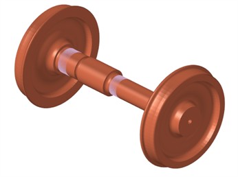
The flexible wheelset model was constructed using ANSYS finite element software, employing solid185 hexahedral elements for mesh discretisation. In the model, three master nodes at the centre of the axle are coupled with a set of nodes on the axle. The interference fit between the wheel and axle was not considered; the assembly was treated as a monolithic part, comprising 483,738 elements and 513,381 nodes. The model incorporates the material density of the wheel and axle, along with Young’s modulus and Poisson’s ratio.
Fig. 2Establishment of the substructure reduction model
a) Finite element modelling of wheelset

b) Master node of wheelset
In order to ensure the accuracy of the simulation, the model is simplified as much as possible by using the substructure reduction method. The Guyuan substructure analysis method involves the selection of 165 main nodes with 990 main degrees of freedom (see Fig. 2(b)) on the wheelset to obtain the reduced superelement of the wheelset. The flexible body information, including the mass and stiffness matrix of the wheelset, is outputted in the .sub format file subsequent to the substructure analysis.
2.2. Modal analysis of wheelset
A modal analysis was first performed on the complete finite element model. The reduced wheelset substructure was then imported into ANSYS, where its free-free modal properties were computed. The first ten flexible modes (excluding rigid-body motions) were extracted. By comparing the modal frequencies and shapes of the reduced model with those of the original full model under unconstrained conditions, the validity of the substructure reduction was confirmed, as shown in Table 2.
The maximum discrepancy between the modal frequencies of the substructure model and the full-degree-of-freedom model does not exceed 0.89 %, confirming the validity of the substructure reduction approach.
2.3. Modelling of rigid-flexible coupled dynamics
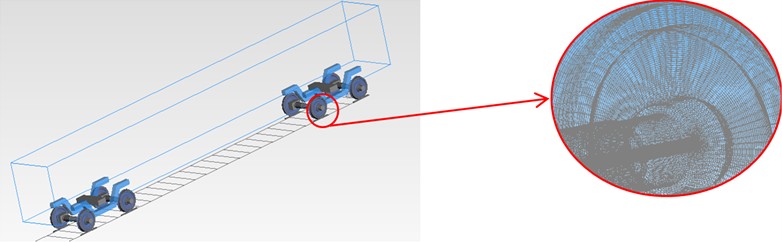
This study establishes a rigid-flexible coupled dynamics model for an inner axle box metro vehicle, with a view to analyse its dynamic response and vibration characteristics. In accordance with the principles of dynamic modelling, both the car body and the bogie frame were simplified into rigid mass bodies. Their respective mass and moment of inertia parameters are provided in Appendix to ensure the validity of the model. The vehicle's main parameters are shown in Appendix Table 1 [27]. Fig. 3 schematically represents the vehicle suspension topology modeled through discrete spring-damper elements. Fig. 4 presents the schematic representation of the rigid-flexible coupled vehicle model implemented within the multi-body dynamics (MBD) environment SIMPACK.
Table 2Comparison of modal frequencies of wheelset
Ordinal number | Substructural model (Hz) | Full-degree-of-freedom model (Hz) | Percentage difference (%) |
1 | 120.21 | 120.2 | 0.01 |
2 | 134.41 | 134.3 | 0.08 |
3 | 134.41 | 134.3 | 0.08 |
4 | 234.42 | 233.9 | 0.22 |
5 | 234.42 | 233.9 | 0.22 |
6 | 364.34 | 361.1 | 0.89 |
7 | 407.36 | 405.8 | 0.38 |
8 | 407.36 | 405.8 | 0.38 |
9 | 482.75 | 480.9 | 0.38 |
10 | 482.75 | 480.9 | 0.38 |
Fig. 3Metro vehicle structure topology
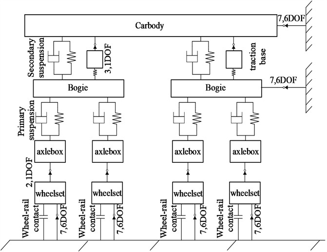
Fig. 4 shows the vehicle-rail coupling model with standard gauge model and LM-type tread. It also shows the rigid-flexible coupling model of flexible wheelset vehicle.
Within the model configuration, the track is represented as a rigid body. Subsequent to the incorporation of wheelset flexibility, the FASTSIM algorithm is utilized in SIMPACK for real-time computation of creep forces. This produces variations in creep forces under excitation, which subsequently influence the dynamic calculations. Consequently, the results derived from the flexible wheelset model partially reflect the influence of wheel-rail contact on the dynamic characteristics.
Vehicle vibration is mitigated through the employment of a system incorporating vibration dampers, rubber stops, and other elastic components. The system’s stiffness varies with the applied load; when the rate of change reaches a critical threshold, the spring force accelerates its increase, thereby exhibiting the “first soft and then hard” nonlinear characteristics.
Fig. 4Vehicle rigid-flexible coupling dynamics model
As demonstrated in Fig. 5(a), the damping force generated by the vibrator exhibits a substantial nonlinear relationship with the relative velocity. Fig. 5(b) illustrates the dynamic force-displacement characteristics of the lateral stop. It has been demonstrated that when the stop compression increases, the rate of change of the stop force also increases, thus demonstrating clear and symmetric nonlinear elastic behaviour.
Fig. 5Nonlinear functions of a vehicle’s secondary suspension
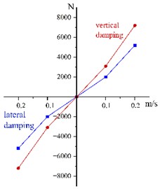
a) Damping characteristics of the damper
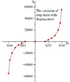
b) Non-linear behaviour of stops
3. Dynamic analysis
The assessment of vehicle dynamics centres on three principal criteria: stability, safety, and ride quality. Stability is assessed via the vehicle's critical speed on straight track. Ride quality is evaluated using carbody accelerations in both the lateral and vertical directions together with the corresponding Sperling indices. Safety, meanwhile, is analysed based on the derailment coefficient, the wheel load reduction rate, and the lateral force of the wheelset. Furthermore, the distinct characteristics of straight and curved track sections are fully considered in this investigation. On curved sections, where safety risks are more pronounced, the analysis is focused primarily on safety metrics. On straight sections, which constitute the majority of the network, the assessment centers on ride comfort indicators. This methodology not only reduces the analytical workload but also sharpens the investigative focus accordingly. Owing to the reduced yaw stiffness resulting from the inboard axle box design, the analysis in this chapter begins with an assessment of the critical speed.
3.1. Vehicle stability analysis
In vehicle stability analysis, the key parameter of interest is the critical speed. On straight track, the hunting critical speed is the lowest speed for a rail vehicle to develop sustained, undamped periodic lateral oscillations.
The hunting oscillation of railway vehicles constitutes a form of self-excited nonlinear vibration. This phenomenon can manifest in forms including Hopf bifurcation, quasi-periodic and chaotic motion. Within the typical operating speed range of the vehicle system, however, the relevant nonlinear behaviour is confined to that arising from Hopf bifurcation and the resulting limit-cycle oscillation [28-29]. Hopf bifurcation can manifest in various forms, with three common types shown in Fig. 6. In the case of subcritical Hopf bifurcation, when the vehicle speed exceeds point A, large amplitude lateral displacement of the wheelset occurs. Please refer [30] for further details on Hopf bifurcation.
From an engineering perspective, two critical speeds are typically defined: the linear critical speed (), which is the threshold at which the system begins to exhibit instability under minor perturbations, and the nonlinear critical speed (), which is the speed point at which the hunting motion disappears as the speed decreases after the system has become unstable under finite disturbances[31-32]. provides a more accurately reflects the vehicle's stability boundary against disturbances in actual operation; therefore, this study focuses on the analysis of [33].
Fig. 6Common types of bifurcations [33]
![Common types of bifurcations [33]](https://static-01.extrica.com/articles/25358/25358-img15.jpg)
a) Subcritical Hopf bifurcations
![Common types of bifurcations [33]](https://static-01.extrica.com/articles/25358/25358-img16.jpg)
b) Supercritical Hopf bifurcation
![Common types of bifurcations [33]](https://static-01.extrica.com/articles/25358/25358-img17.jpg)
c) Supercritical Hopf bifurcation
The nonlinear critical speed () was obtained via the standard ramp method, which is recognized for its reliability and efficiency in both engineering applications and academic research [32]. The specific procedure was implemented as follows: an initial finite-amplitude disturbance, introduced as a 4.5 mm lateral displacement to the wheelset at the start of the simulation , served as the excitation. The system's speed was then gradually decreased from a sufficiently high initial value (e.g., 250 km/h), where significant hunting instability was evident, in steps of 1 km/h. At each speed step, the time history of the wheelset’s lateral displacement was monitored. The system was considered to have converged (stable) at a given speed if the peak displacement amplitude decayed and remained below a threshold of 2 mm; otherwise, it was deemed divergent (unstable). The highest speed at which the system recovered stability from an unstable state was identified as the nonlinear critical speed, . Applying this methodology, the values for both the rigid and rigid-flexible coupled vehicle models were calculated under varying primary suspension vertical stiffnesses, and the comparative results are presented in Fig. 7.
As illustrated in Fig. 7, an increase in the primary suspension vertical stiffness from 1.2 MN/m to 3.2 MN/m results in an initial rise followed by stabilization of the critical speed for the rigid-body model. Specifically, the critical speed is observed to increase from 244 km/h to a maximum of 253 km/h at 2.2 MN/m, beyond which it remains constant at 251 km/h.
Over the identical stiffness range, the critical speed of the rigid-flexible coupled model exhibits only minor variations, with changes not exceeding 2 km/h. This indicates that the influence of primary suspension vertical stiffness on critical speed is highly limited and may be regarded as negligible in the rigid-flexible coupled model.
Comparative analysis demonstrates that the rigid-flexible coupled model consistently exhibits a lower critical speed than the rigid-body configuration across the evaluated stiffness range. As shown in Fig. 7(b), the wheelset lateral displacement of the rigid-flexible coupled model remains significant, while that of the rigid-body model approaches zero. This finding indicates that the adoption of a flexible modeling approach for the wheelset reduces the vehicle’s critical speed.
Fig. 7Critical speed and lateral displacement
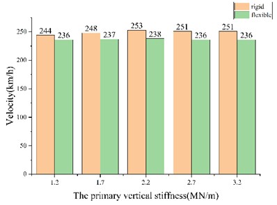
a) Critical speed of vehicle
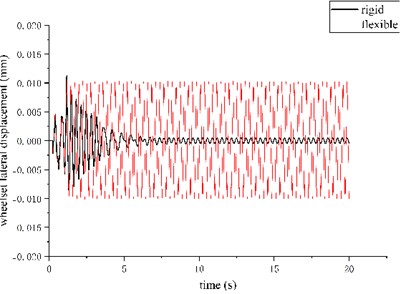
b) The lateral displacement of wheelset
3.2. Straight-line ride quality analysis
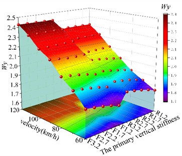
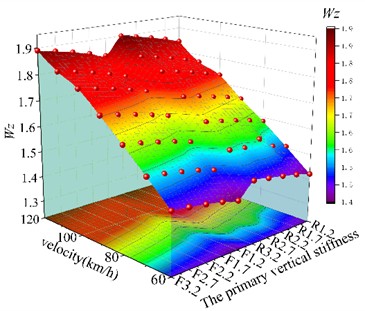
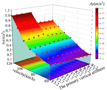
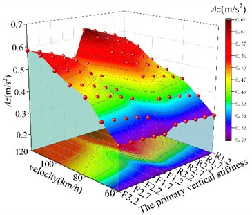
For the straight-track analysis, the operating speed was varied from 60 to 120 km/h in increments of 10 km/h. The primary suspension stiffness ranged from 1.2 to 3.2 MN/m, increased in steps of 0.5 MN/m. Track excitation was modelled using the US five-level irregularity spectrum. A comparative evaluation of the rigid–flexible coupled and multi-rigid-body models was conducted, assessing straight-track ride comfort via Sperling indices and running accelerations across the specified stiffness range. The results presented in Fig. 8 correspond to the maximum values obtained.
In the figures, the labels F and R denote the rigid-flexible coupling model and the multi-rigid-body model, respectively. The appended numerical value indicates the primary vertical stiffness in MN/m; for instance, ‘F2.2’ refers to the rigid-flexible model with a stiffness of 2.2 MN/m. The symbols , , and represent the lateral Sperling index, vertical Sperling index, lateral acceleration, and vertical acceleration.
Fig. 8 shows a consistent upward trend in all vehicle performance indicators with increasing speed. Variations in primary suspension vertical stiffness are observed to have a negligible effect on , , indicating that these metrics remain largely invariant across the tested stiffness range. In contrast, the stiffness variation exerts a more pronounced influence on , . The analysis confirms that higher primary suspension stiffness increases both the Sperling indices and the running accelerations, thereby resulting in a degradation of ride quality.
Within the speed range of 60-80 km/h, the ride comfort indices of the rigid-flexible coupled model are found to be virtually identical to those of the rigid-body model. However, at higher speeds between 100 and 120 km/h, the lateral acceleration and lateral Sperling index of the coupled model are observed to be significantly higher than those of the rigid-body model. This suggests a decline in the vehicle’s lateral ride comfort with increasing operating speed under the flexible wheelset model, whereas its effect on vertical comfort is negligible. Under the analyzed operating conditions, all performance indices satisfy the requirements specified in the GB/T 5599 standard.
Therefore, in the analysis of straight-track ride quality, it is recommended to first establish an appropriate value for the primary suspension vertical stiffness. Subsequently, a rigid-flexible coupled analysis should be conducted using the flexible wheelset model. Although the flexible wheelset increases the lateral ride comfort indices, the rigid-flexible coupled approach provides a more realistic representation of the vehicle's dynamic behaviour. Consequently, the results obtained through this methodology offer enhanced reliability and practical relevance.
Fig. 8Vehicle running stability under straight-track excitation (US five-level spectrum). Surfaces are plotted for both the rigid-flexible coupled (F) and multi-rigid-body (R) models, with the numeric suffix denoting the stiffness value in MN/m
a) Lateral ride quality (Sperling index)
b) Vertical ride quality (Sperling index)
c) Lateral vibration acceleration of car body
d) Vertical vibration acceleration of car body
3.3. Curve-line running safety analysis
The curve negotiation conditions were defined in compliance with the relevant provisions of the metro design specification, which specifies that the maximum allowable unbalanced lateral acceleration should not exceed 0.4 m/s2. A corresponding maximum deficient superelevation of 60 mm was adopted in accordance with this requirement. For each curve radius, appropriate superelevation values and transition curve lengths were assigned based on the specifications. Track excitation was simulated using the U.S. five-level irregularity spectrum. The resulting curve parameters and operating conditions are summarized in Table 3.
Table 3Setting up of curved lines
Curve condition | Radius (m) | Maximum speed (km/h) | Superelevation (m) | Transition curve length (m) | Curve length (m) |
1 | 300 | 74 | 0.16 | 100 | 100 |
2 | 400 | 89 | 0.13 | 130 | 100 |
3 | 500 | 100 | 0.09 | 150 | 100 |
4 | 600 | 104 | 0.07 | 110 | 100 |
5 | 800 | 110 | 0.06 | 90 | 100 |
6 | 1000 | 120 | 0.055 | 80 | 100 |
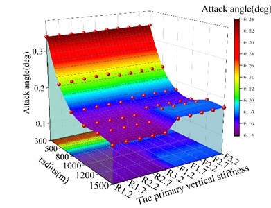
The simulation results are shown in Fig. 9, which shows the derailment coefficient , the wheelset lateral force , and the wheel load reduction rate . The primary suspension vertical stiffness was varied from 1.1 to 3.2 MN/m in increments of 0.5 MN/m. The wear index, also included, is defined as the product of the wheel-rail lateral force and the wheelset attack angle.
Fig. 9Vehicle running safety curve-track excitation (US five-level spectrum). Surfaces are plotted for both the rigid-flexible coupled (F) and multi-rigid-body (R) models, with the numeric suffix denoting the stiffness value in MN/m
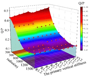
a) Derailation coefficient
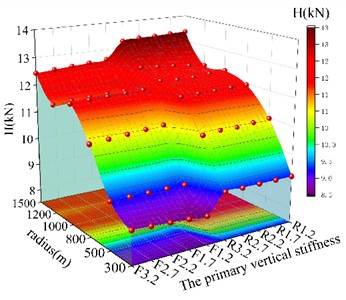
b) Wheel load reduction rate
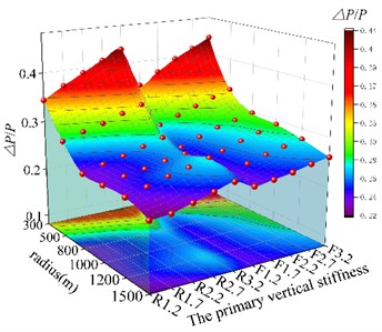
c) Wheelset lateral force
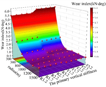
d) Wear index
e) Attack angle of the wheelset
Fig. 9 indicates that most vehicle safety indicators generally decrease with increasing curve radius. An exception is observed in the lateral wheelset force, which increases due to greater centrifugal effects as the vehicle operates at higher speeds on larger radii. Although the lateral force increases, the wear index – defined as the product of lateral force and wheelset attack angle – remains relatively low on large-radius curves, indicating favorable curving performance.
The results obtained from the rigid-flexible coupled model on curves show close agreement with those from the rigid-body model. This indicates that the influence of wheelset flexibility on curve safety is negligible under the selected operating conditions. Therefore, for the analysis of curving dynamic performance in these scenarios, the rigid-flexible coupled modeling approach can be omitted.
Elevation of the primary suspension vertical stiffness exerts a noticeable influence on the derailment coefficient and the wheel-load reduction rate, with both metrics progressively increasing as the stiffness rises. Despite the elevation in certain performance indices with higher stiffness, all results remain within the standard limits specified by GB/T 5599-2019.
4. Axle box vibration analysis
As indicated by the bending moment diagram, the axle box in the built-in configuration is positioned internally within the wheel. This arrangement results in a reduction of the lever arm through which wheel-rail forces act on the axle box bearing, thereby decreasing the overall axle bending moment. However, a consequence of this design is a substantial increase in the local bending moment at the axle box itself.
When the wheelset is modeled as a rigid body, both the wheelset and axle box are treated as non-deformable components. Consequently, minimal dissipation of the nonlinear vibration energy induced by wheel-rail excitation occurs during transmission through these components. In contrast, a flexible wheelset model accommodates elastic deformation, which absorbs a portion of this vibrational energy. Nevertheless, the accompanying alterations in wheel-rail contact conditions more significantly excite nonlinear vibrations in the axle box region. This response more accurately replicates actual operational behaviour. The phenomenon originates from the operational deformation of the flexible wheelset, which dynamically modifies the wheel-rail contact geometry. These perturbations generate higher-frequency vibrations that can directly influence vehicle stability.
This section analyzes the vibration characteristics of the axle box, with focus on its acceleration in both time and frequency domains, and assesses the associated resonance risk. The vibration measurement point was positioned at the center of the axle box top surface. This location lies on the primary load path through which wheel-rail forces are transmitted via the wheelset journals to the bearings, making it directly subject to wheelset vibrations and thus representative of wheelset dynamic behaviour. Furthermore, in the inboard axle box design, this region corresponds to a critical area of significantly increased local bending moment, enabling effective monitoring of vibrational characteristic changes. The point also benefits from high structural rigidity and is situated away from local discontinuities, thereby avoiding interference from local modes and ensuring that the measured response represents the global vibration of the axle box. To effectively assess the vibration characteristics, the operating conditions selected for this analysis correspond to the maximum-speed scenarios derived from the straight-line and curved-track dynamic performance calculations presented earlier.
4.1. Straight-line working condition analysis
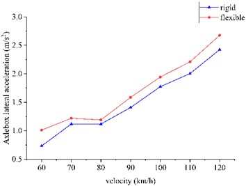
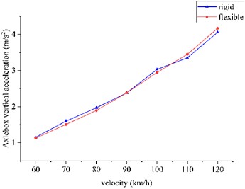
The straight-line operational design aligns with the dynamics analysis methodology. The peak lateral and vertical acceleration values of the axle box assembly, alongside corresponding time-domain wave forms and derived displacement profiles, are detailed in Fig. 10 and Fig. 11.
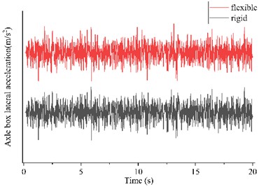
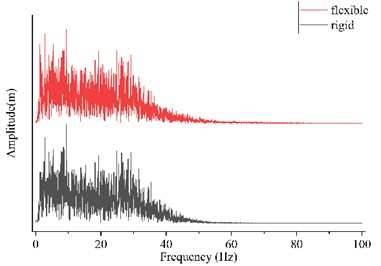
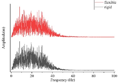
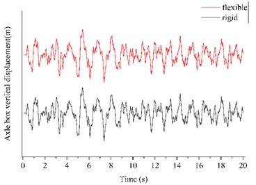
The raw temporal wave forms and corresponding frequency-domain spectra associated with peak axle box vibration acceleration at 120 km/h were extracted and subjected to analytical processing, as presented in Fig. 12.
Fig. 10vibration acceleration of axle box
a) Lateral acceleration of axle box
b) Vertical acceleration of axle box
Fig. 11Raw waveform and frequency domain plot
a) Raw waveform of lateral vibration acceleration
b) Frequency domain plot of lateral vibration acceleration

c) Raw waveform of vertical vibration acceleration
d) Frequency domain plot of vertical vibration acceleration
e) Axle box vertical displacement
As shown in Fig. 10 and 11, the axle-box vibration acceleration values of the two models are comparable and increase with speed. The dominant frequency of the vibration lies mainly below 40 Hz, indicating no risk of resonance between the axle box and the wheelset. Moreover, the rigid-flexible coupled model exhibits smaller fluctuations in axle-box acceleration compared to the rigid-body model. Overall, the flexible-wheelset model yields smoother variations in axle-box vibration acceleration.
As shown in Figs. 10 and 11, the axle-box vibration acceleration values of both models are observed to be comparable and exhibit an increasing trend with speed. Spectral analysis shows that the dominant vibration frequencies are below 40 Hz. Since the natural frequencies of the wheelset are all above 100 Hz, there is no risk of resonance between the axle box and the wheelset. Furthermore, the rigid-flexible coupled model demonstrates reduced fluctuation amplitudes in axle-box acceleration compared to the rigid-body model. Overall, the flexible-wheelset configuration yields smoother variations in axle-box vibration acceleration response.
In contrast to the rigid model, the coupled modeling approach incorporates wheelset flexibility, which provides vibration attenuation along the transmission path from the track to the axle. This results in generally lower acceleration levels at the axle-box measurement location. Within the investigated speed range, the influence of wheelset flexibility on axle-box vibration may therefore be regarded as negligible in the analytical assessment.
4.2. Curve condition analysis
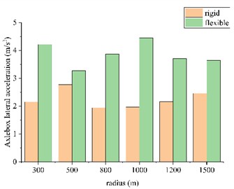
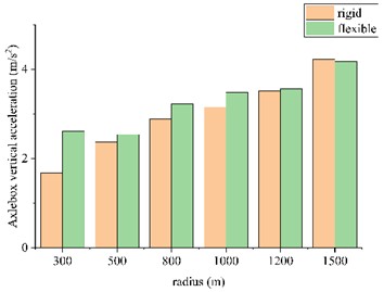
The curve condition operational design aligns with the dynamics analysis methodology. The peak lateral and vertical acceleration values of the axle box assembly, alongside corresponding time-domain wave forms and derived displacement profiles, are detailed in Fig. 12 and Fig. 13.
Fig. 12Vibration acceleration of axle box
a) Lateral acceleration of axle box
b) Vertical acceleration of axle box
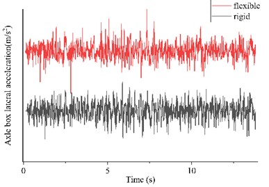
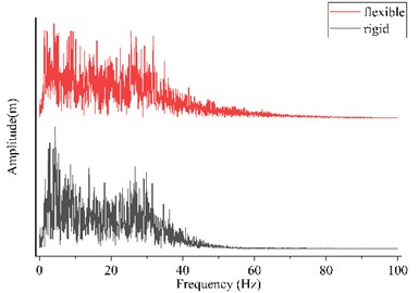
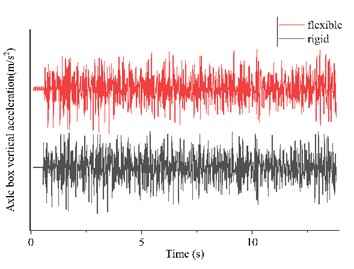
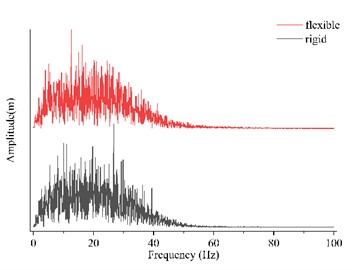
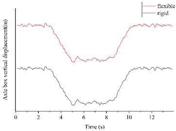
The raw and frequency domain waveforms corresponding to the maximum vibration acceleration of the axle box at a radius of 1500 m are taken for analysis and the results are shown in Fig. 13.
As shown in Fig. 12 and 13, under curved-track operating conditions, the axle-box vibration accelerations obtained from the rigid-body model and the rigid-flexible coupled model are generally similar. The primary distinction is observed in occasional higher-amplitude peaks present in the coupled model. The vibration energy is concentrated predominantly below 40 Hz. This frequency range is significantly lower than the natural modes of the wheelset, indicating no resonance risk between the axle box and the wheelset.
Compared with the rigid model, the acceleration curve from the coupled model exhibits reduced fluctuations and smoother variations. This behaviour may be attributed to the damping effect of the flexible wheelset, which attenuates a portion of the vibration transmitted from the track to the axle box. Under the speed and curve conditions investigated in this study, the influence of wheelset flexibility on axle-box vibration is limited and may be considered secondary in engineering analysis.
Fig. 13Raw waveform and frequency domain plot
a) Raw waveform of lateral vibration acceleration
b) Frequency domain plot of lateral vibration acceleration
c) Raw waveform of vertical vibration acceleration
d) Frequency domain plot of vertical vibration acceleration
e) Axle box vertical displacement
5. Conclusions
This study began with a theoretical mechanics analysis of the force distribution in the built-in axle-box bogie, evaluating the influence of primary suspension vertical stiffness on the vehicle’s anti-roll capability. Subsequently, the wheelset was modelled with flexibility, and a dynamic model of the vehicle equipped with the built-in axle-box bogie was established, incorporating the nonlinear characteristics of the suspension system. Vehicle dynamic performance indicators under varying operational conditions and vertical stiffness values were analysed, while the vibration characteristics of the axle box were examined in both the time and frequency domains. The key findings are summarised below:
1) Theoretical analysis of the inner axle box: The vehicle’s anti-roll capacity is lowered by the reduced semi-lateral span of the primary suspension system in the inboard axle box configuration. Furthermore, the resistance to yaw stiffness of the wheelset is reduced, its lateral motion is intensified, and a consequent decrease in the vehicle’s critical speed is observed. Even with identical primary suspension vertical stiffness, the anti-roll capability of the built-in axle-box bogie remains significantly lower than that of the external configuration. These variations are confirmed through simulation and analysis to remain within acceptable limits, with no critical dynamic anomalies detected.
2) Influence of flexible wheelsets on the critical speed of inner axle box bogies: An increase in the primary suspension vertical stiffness results in an initial rise followed by stabilization of the critical speed for the rigid-body model. In contrast, the critical speed of the rigid-flexible coupled model exhibits minimal variation with stiffness changes and remains consistently lower than that of the rigid-body configuration. This behaviour indicates that a moderate increase in vertical stiffness suppresses lateral wheelset motion and raises the critical speed in the rigid-body model, whereas excessive stiffness intensifies lateral oscillations and reduces it. However, the primary suspension vertical stiffness demonstrates negligible influence on the critical speed of the coupled model. The incorporation of wheelset flexibility amplifies lateral motion, consequently leading to a reduction in critical speed.
3) Straight-line running ride quality analysis of vehicle: A consistent increase in vehicle ride quality indices is observed with rising speed. Variations in primary suspension vertical stiffness exert a more significant influence on the vertical Sperling index and vertical acceleration, with both metrics increasing as stiffness elevates. Within the speed range of 100-120 km/h, the lateral vibration acceleration and lateral Sperling index of the rigid-flexible coupled model exceed those of the rigid-body model, indicating that the incorporation of wheelset flexibility adversely affects lateral ride quality. In contrast, at speeds below 80 km/h, the indices obtained from both models are observed to be nearly identical, suggesting that the influence of the flexible wheelset may be considered negligible in this lower speed regime. Therefore, in high-speed straight-track dynamic analysis, it is necessary to account for wheelset flexibility. All calculated indices are found to comply with the requirements specified in the GB/T 5599 standard.
4) Curve-line running safety analysis of vehicle: An increase in the primary suspension vertical stiffness results in a gradual rise in both the derailment coefficient and wheel load reduction rate. The dynamic indices obtained from the rigid-body model and the rigid-flexible coupled model remain largely consistent across various curve conditions. This indicates that excessively high primary suspension vertical stiffness reduces curve negotiation safety, while the influence of the flexible wheelset is negligible. Therefore, in the analysis of curving dynamics, the wheelset can be modeled as a rigid body, provided that an appropriate value is selected for the primary suspension vertical stiffness. All simulation results confirm that both the flexible and rigid wheelset models satisfy the safety thresholds specified in GB/T 5599-2019.
5) The analysis of axle box vibration: Under both straight and curved track conditions, the axle-box acceleration results obtained from the rigid-body model and the rigid-flexible coupled model show substantial agreement. The primary difference observed is the occasional occurrence of higher amplitude vibration peaks in the coupled model. Frequency domain analysis reveals that the dominant frequency components of the axle-box vibration acceleration remain predominantly below 40 Hz. This frequency range is significantly lower than the natural modes of the wheelset, indicating no resonance risk between the axle box and the wheelset. In the time-domain waveforms, the axle-box acceleration of the coupled model generally exhibits reduced fluctuations and smoother variation characteristics. This behaviour is attributed to the material damping inherent in the flexible wheelset, which attenuates a portion of the vibration transmitted from the track. Based on these findings, the influence of wheelset flexibility on axle-box vibration acceleration may be considered negligible within the scope of the present investigation.
While the present investigation provides a comprehensive numerical analysis of the dynamics of an inner axle box bogie with a flexible wheelset, several limitations indicate directions for future research. The analysis was conducted exclusively using simulation-based models, constrained by the lack of experimental data. Physical validation under controlled operational conditions would enable verification of the predicted dynamic responses and yield a more accurate understanding of the influence of wheelset flexibility on the integrated axle box assembly. Experimental measurements would also contribute to the refinement of modeling assumptions, particularly concerning boundary conditions and damping characteristics.
Additionally, the evolution of the wheel-rail contact patch under the influence of wheelset flexibility was not examined in detail in this investigation. Future research should emphasize comparative analysis of contact patch behaviour for both inner and outer axle box configurations employing flexible wheelset models. Such analysis would elucidate how structural flexibility modifies contact geometry, pressure distribution, and wear progression, potentially contributing to optimized bogie design and suspension tuning.
This comprehensive analysis yields critical insights for the optimized design of inner axle box bogies, thereby enhancing dynamic performance and operational safety under varying service conditions.
References
-
H. H. Wang and Y. X. Feng, “Problems and countermeasures in the development of urban rail transit in China,” (in Chinese), Economic Research Guide, Vol. 2023, No. 21, pp. 41–43, 2023.
-
H. Wang, A. Gu, Q. Fan, X. Xing, and J. Liu, “Research on vibration characteristics of a flexible vehicle-ladder track system,” Urban Rail Transit, Vol. 10, No. 1, pp. 13–27, Jan. 2024, https://doi.org/10.1007/s40864-023-00209-x
-
Y. Qi, H. Dai, P. Ao, X. Cui, and W. Mao, “Research on wheel wear evolution of inside axlebox metro vehicles,” Industrial Lubrication and Tribology, Vol. 77, No. 6, pp. 896–907, Dec. 2025, https://doi.org/10.1108/ilt-07-2024-0256
-
B. W. Wu, G. X. Chen, J. Z. Lv, Q. Zhu, X. N. Zhao, and X. Kang, “Effect of the axlebox arrangement of the bogie and the primary suspension parameters on the rail corrugation at the sharp curve metro track,” Wear, Vol. 426-427, pp. 1828–1836, Jan. 2019, https://doi.org/10.1016/j.wear.2019.01.038
-
Y. H. Liu, F. Li, M. H. Fu, and Y. H. Huang, “Development and application of inside suspension bogies,” (in Chinese), Foreign Rolling Stock, Vol. 42, No. 6, pp. 24–28, 2005.
-
Z. L. Liang, M. R. Chi, and W. B. Cai, “Research on key suspension parameter matching of high speed inner axle-box bogie,” (in Chinese), Railway Standard Design, pp. 1–11, Feb. 2024, https://doi.org/10.13238/j.issn.1004-2954.202402070003
-
S. C. Wu, Y. X. Liu, C. H. Li, G. Z. Kang, and S. L. Liang, “On the fatigue performance and residual life of intercity railway axles with inside axle boxes,” Engineering Fracture Mechanics, Vol. 197, pp. 176–191, Jun. 2018, https://doi.org/10.1016/j.engfracmech.2018.04.046
-
L. Baeza, P. Vila, G. Xie, and S. D. Iwnicki, “Prediction of rail corrugation using a rotating flexible wheelset coupled with a flexible track model and a non-Hertzian/non-steady contact model,” Journal of Sound and Vibration, Vol. 330, No. 18-19, pp. 4493–4507, Aug. 2011, https://doi.org/10.1016/j.jsv.2011.03.032
-
Z. Wang, W. Zhang, Z. Yin, Y. Cheng, G. Huang, and H. Zou, “Effect of vehicle vibration environment of high-speed train on dynamic performance of axle box bearing,” Vehicle System Dynamics, Vol. 57, No. 4, pp. 543–563, May 2019, https://doi.org/10.1080/00423114.2018.1473615
-
M. Lu et al., “Advantages and disadvantages analysis and dynamics simulation of 200 km/h axle box built-in bogie,” (in Chinese), Rolling Stock, Vol. 61, No. 5, pp. 44–50, 2023.
-
Y. H. Zhang, M. R. Chi, S. L. Liang, W. B. Cai, and Y. C. Xie, “Analysis of the causes of abnormal vibration in high-speed EMU axle box and solutions,” (in Chinese), Railway Standard Design, pp. 1–9, Dec. 2024, https://doi.org/10.13238/j.issn.1004-2954.202312280002
-
Y. Hou et al., “Measured dynamic load distribution within the in situ axlebox bearing of high-speed trains under polygonal wheel-rail excitation,” Railway Engineering Science, Vol. 32, No. 4, pp. 444–460, Apr. 2024, https://doi.org/10.1007/s40534-024-00344-6
-
Z. Wang, Y. Cheng, P. Allen, Z. Yin, D. Zou, and W. Zhang, “Analysis of vibration and temperature on the axle box bearing of a high-speed train,” Vehicle System Dynamics, Vol. 58, No. 10, pp. 1605–1628, Oct. 2020, https://doi.org/10.1080/00423114.2019.1645340
-
J. Zhang and J. M. Zhao, “Analysis of the effect of wheel polygon on the vibration characteristics of the axle box,” (in Chinese), Journal of Dalian Jiaotong University, Vol. 45, No. 6, pp. 66–71, Jun. 2024, https://doi.org/10.13291/j.cnki.djdxac.2024.06.011
-
F. R. Li et al., “Non-Gaussian characteristics and distribution of axle box vibration in railway vehicles,” (in Chinese), Noise and Vibration Control, Vol. 44, No. 4, pp. 218–223, 2024.
-
W. Fang, J. Martinez-Casas, and S. Bruni, “A time-domain model for the study of high-frequency wheelset-track interaction,” Urban Rail Transit, Vol. 3, No. 4, pp. 203–213, Apr. 2017, https://doi.org/10.1007/s40864-017-0049-1
-
L. H. Fang, Q. H. Guan, and Z. F. Wen, “Influence of wheelset bending on wheel-rail contact of vehicles with inside and outside axle boxes,” (in Chinese), Journal of Central South University (Science and Technology), Vol. 53, No. 8, pp. 3259–3269, 2022.
-
W. Wang, Z. Liu, Q. Li, and H. Zou, “Research on vibration behavior of 300km/h EMU trailer wheel set,” in Proceedings, Vol. 7522, p. 752234, Dec. 2009, https://doi.org/10.1117/12.851275
-
C. Casanueva, A. Alonso, I. Eziolaza, and J. G. Giménez, “Simple flexible wheelset model for low-frequency instability simulations,” Proceedings of the Institution of Mechanical Engineers, Part F: Journal of Rail and Rapid Transit, Vol. 228, No. 2, pp. 169–181, Dec. 2012, https://doi.org/10.1177/0954409712468253
-
G. Bethel Lulu, R. Chen, P. Wang, J. Xu, and J. Chen, “Effect of polygonal wheel on the vehicle-track dynamic interaction in turnout and its transmission to the trailer bogie wheels,” Vehicle System Dynamics, Vol. 62, No. 7, pp. 1713–1738, Jul. 2024, https://doi.org/10.1080/00423114.2023.2251618
-
Z. Song, F. Wang, X. Hu, D. Cheng, and Q. Li, “Influences of wheel polygon amplitude on wheel-rail vibration and sound radiation,” Journal of Low Frequency Noise, Vibration and Active Control, Vol. 42, No. 2, pp. 477–495, Jan. 2023, https://doi.org/10.1177/14613484231152850
-
S. Mo et al., “Research on rigid-flexible coupling nonlinear dynamics of light commercial vehicle considering frame flexibility,” International Journal of Non-Linear Mechanics, Vol. 170, p. 104949, Mar. 2025, https://doi.org/10.1016/j.ijnonlinmec.2024.104949
-
S.-Q. Zhong and X.-S. Jin, “Effect of the first two wheelset bending modes on wheel-rail contact behavior,” Journal of Zhejiang University Science A, Vol. 15, No. 12, pp. 984–1001, Dec. 2014, https://doi.org/10.1631/jzus.a1400199
-
S. Zhong, X. Xiao, Z. Wen, and X. Jin, “Effect of wheelset flexibility on wheel-rail contact behavior and a specific coupling of wheel-rail contact to flexible wheelset,” Acta Mechanica Sinica, Vol. 32, No. 2, pp. 252–264, 2015, https://doi.org/10.1007/s10409-015-0441-6
-
M. Lu, “Research on dynamics performance of the 200 km/h inner axle-box bogie,” Southwest Jiaotong University, Chengdu, China, 2021, https://doi.org/10.27414/d.cnki.gxnju.2021.001108
-
X. L. Li and G. Shen, “Research on the flexibility coefficient of rail vehicles,” (in Chinese), Rolling Stock, Vol. 49, No. 8, pp. 4–6, 2011.
-
Y. Bao, W. Zhai, C. Cai, X. Yuan, and Y. Li, “Impact coefficient analysis of track beams due to moving suspended monorail vehicles,” Vehicle System Dynamics, Vol. 60, No. 2, pp. 653–669, Oct. 2020, https://doi.org/10.1080/00423114.2020.1828595
-
J. P. Meijaard and A. D. de Pater, “Railway vehicle systems dynamics and chaotic vibrations,” International Journal of Non-Linear Mechanics, Vol. 24, No. 1, pp. 1–17, Jan. 1989, https://doi.org/10.1016/0020-7462(89)90007-3
-
H. Dong, B. Zhao, and Y. Deng, “Instability phenomenon associated with two typical high speed railway vehicles,” International Journal of Non-Linear Mechanics, Vol. 105, pp. 130–145, Oct. 2018, https://doi.org/10.1016/j.ijnonlinmec.2018.06.006
-
H. True, “Multiple attractors and critical parameters and how to find them numerically: The right, the wrong and the gambling way,” Vehicle System Dynamics, Vol. 51, No. 3, pp. 443–459, Mar. 2013, https://doi.org/10.1080/00423114.2012.738919
-
K. Zboinski and M. Golofit-Stawinska, “Determination and comparative analysis of critical velocity for five objects of railway vehicle class,” Sustainability, Vol. 14, No. 11, p. 6649, May 2022, https://doi.org/10.3390/su14116649
-
S. Stichel, “Limit cycle behaviour and chaotic motions of two-axle freight wagons with friction damping,” Multibody System Dynamics, Vol. 8, No. 3, pp. 243–255, Oct. 2002, https://doi.org/10.1023/a:1020990128895
-
X. Hu et al., “Dynamic analysis of cross brace anti-warp stiffness performance for heavy haul freight wagon,” Vehicle System Dynamics, pp. 1–23, Mar. 2025, https://doi.org/10.1080/00423114.2025.2473465
About this article

The authors have not disclosed any funding.
The datasets generated during and/or analyzed during the current study are available from the corresponding author on reasonable request.
Yufeng Ma: experimental design, validation, and manuscript writing. Yunhua Huang: research investigation and oversight. Xu Hu: revision and supervision.
The authors declare that they have no conflict of interest.

