Abstract
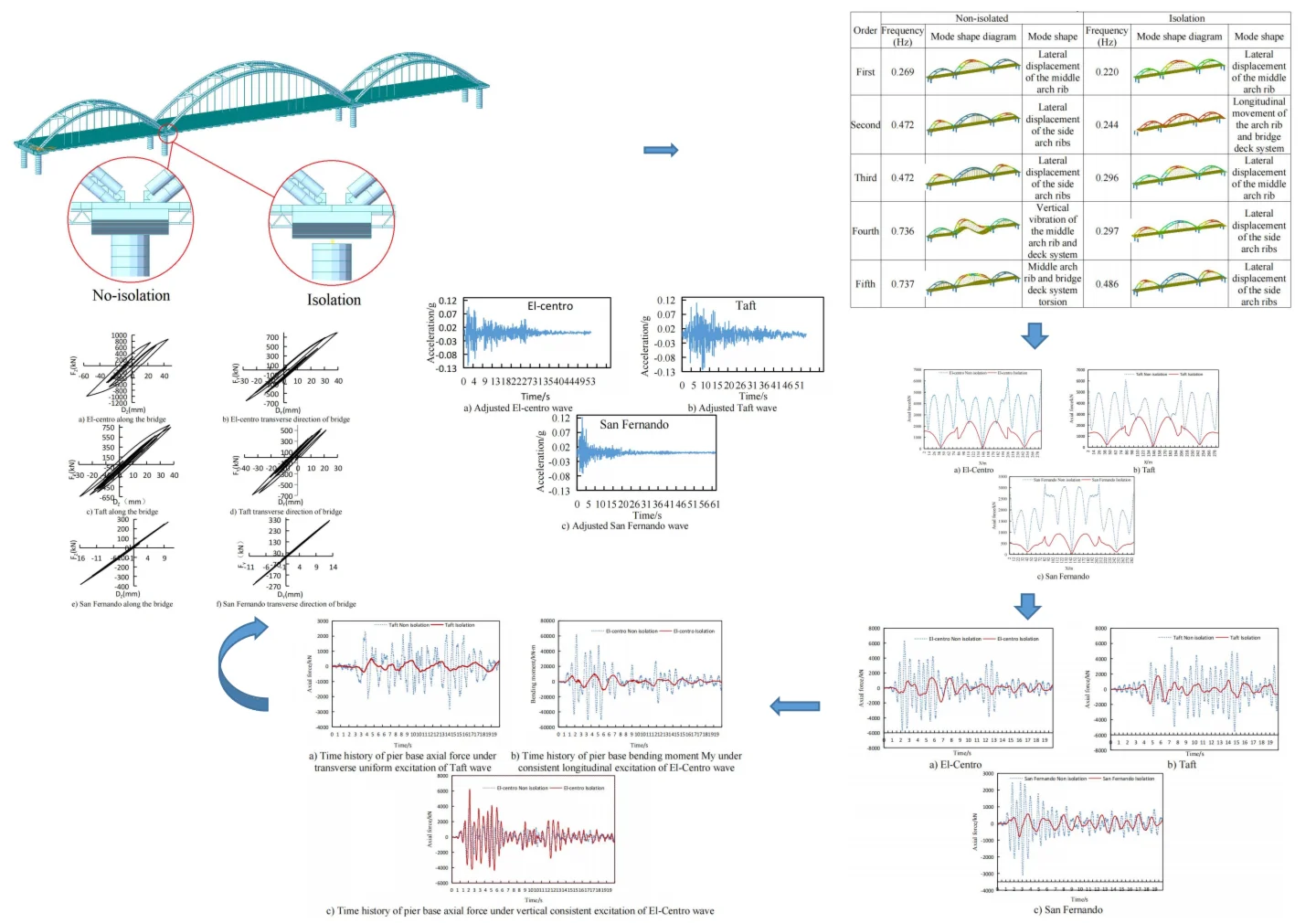
To conduct a comparative analysis of the differences between non-isolated and isolated structures of a multi-span through arch bridge under uniform seismic excitation in different directions, a three-span continuous through concrete-filled steel tube arch bridge was selected. Using the large-scale finite element analysis software MIDAS Civil, a non-isolated model of the actual bridge and an isolated model with lead-rubber bearings added to the top of the piers were established respectively. Dynamic characteristic analysis and comparison were carried out for the two models. Three actual seismic waves were selected to apply longitudinal, transverse, and vertical seismic excitations to the two models respectively. The arch rib internal forces, displacements, and velocities of the two structural models, the maximum internal forces of the piers, the maximum acceleration of the bridge deck, and the hysteretic curves of the isolated bearings were analyzed. It is concluded that under the action of longitudinal and transverse seismic excitations, the isolated model with lead-rubber bearings exhibits a significant isolation effect.
Highlights
- To conduct a comparative analysis of the differences between non-isolated and isolated structures of a multi-span through arch bridge under uniform seismic excitation in different directions.
- Dynamic characteristic analysis and comparison were carried out for the two models. Three actual seismic waves were selected to apply longitudinal, transverse, and vertical seismic excitations to the two models respectively.
- The arch rib internal forces, displacements, and velocities of the two structural models, the maximum internal forces of the piers, the maximum acceleration of the bridge deck, and the hysteretic curves of the isolated bearings were analyzed.
1. Introduction
In recent years, global earthquakes have occurred with increased frequency, and research on non-isolated and isolated structures within the engineering community has remained ongoing. It is particularly crucial for bridges to maintain their structural safety and traffic accessibility after an earthquake. Among various bridge types, arch bridges are widely adopted in engineering practices, attributed to their aesthetic appeal and the efficient utilization of material compressive properties. With the rapid advancement of information technology, the refinement of relevant computational theories, and the maturation of construction techniques, the span lengths and number of spans of arch bridges have been continuously increasing. As the theory governing bridge seismic response analysis has advanced, the design of seismic isolation and mitigation for bridges has garnered extensive attention and undergone rapid development since the 1970s [1-3]. Xia et al. investigated the application of seismic isolation technology in long-span continuous beam bridges [4]; Li et al. examined the seismic response parameters of isolated beam bridges under near-fault earthquake excitations [5]; Zhang et al. conducted a study on the near-fault seismic response analysis of isolated skew bridges, taking into account the environmental temperature effects of Lead-Rubber Bearings (LRBs) and heat generation in lead cores [6]; Zhao et al. analyzed the seismic response of isolated bridges equipped with rotating mass friction dampers and displacement-limited friction pendulums [7]. Additionally, numerous scholars have carried out relevant research on bridge seismic isolation and mitigation [8-10], while several international scholars have also contributed to this field [11-13]. However, the majority of these studies have focused on beam bridges, cable-stayed bridges, and suspension bridges. Research related to arch bridges has primarily centered on seismic resistance and vibration mitigation control [14-16], whereas studies on seismic isolation for arch bridges – particularly for through arch bridges – remain relatively scarce.
A substantial number of multi-span through arch bridges have been constructed in China, and more such bridges are planned for future development. Consequently, it is of great significance to apply uniform seismic excitations to multi-span through arch bridges in different directions, and to conduct a comparative study on the differences in response behaviors and isolation effectiveness between non-isolated and isolated structural models.
While previous studies have extensively investigated the seismic performance of multi-span through-type concrete-filled steel tube (CFST) arch bridges, a systematic comparative analysis of their responses under conventional seismic-resistant versus seismic-isolated designs remains limited. This study fills this gap by presenting a comprehensive comparative analysis of a multi-span through-type CFST arch bridge subjected to uniform seismic excitations in the longitudinal, transverse, and vertical directions. The novelty of this work lies in its direct, quantitative comparison of internal force and acceleration responses between the two structural systems across all three seismic components. The findings, which demonstrate significant reductions in arch-rib internal forces (60 %-80 %) and deck accelerations (70 %-90 %) with lead rubber bearings (LRBs), provide valuable empirical evidence and practical references for the seismic design optimization of similar long-span bridge structures.
2. Finite element model
A seismic model of an actual three-span through concrete-filled steel tube tied arch bridge was established using the large-scale finite element analysis software MIDAS Civil, and an isolation model – with lead-rubber isolation bearings installed at the top of the piers – was also constructed. The configuration of the isolation bearings in MIDAS Civil followed the workflow: Boundary → General Connection → General Connection Properties → Add, where the parameters of the lead-rubber isolation bearings were specified as detailed in Table 1.
The bridge features two side spans, each with a length of 87 meters, and a middle span of 127 meters. All arch rib cross-sections adopt a dumbbell shape, with circular steel tubes used for both the upper and lower segments. Specifically, the middle arch ribs utilize steel tubes with a diameter of 1.2 meters for the upper and lower chords, while the side arch ribs employ steel tubes with a diameter of 1.0 meter for their upper and lower chords. The upper and lower steel tubes are connected via steel batten plates, and each steel tube is filled with C50 micro-expansive concrete. “*”-shaped cross-braces are installed at the top of both the side and middle arch ribs; additionally, the side arches are equipped with two sets of “K”-shaped cross-braces, and the middle arch is furnished with four sets of “K”-shaped cross-braces.
In the finite element model, beam elements were used to simulate the piers, longitudinal girders, cross girders, arch ribs, and cross-braces; rod elements were adopted for the hangers; tension-only elements were applied to the tie rods; and plate elements were employed for the bridge deck. Elastic connections were set between the piers and the main girders, with the bottom of each pier treated as a fixed support. The finite element model is illustrated in Fig. 1. A coordinate system was established such that the longitudinal, transverse, and vertical directions of the bridge correspond to the , , and axes, respectively.
Table 1Lead-core rubber support parameters
Support plane dimension (mm×mm) | Lead core yield force (kN) | Pre-yield stiffness (kN/mm) | Post-yield stiffness (kN/mm) | Horizontal equivalent stiffness (kN/mm) |
1320×1320 | 964 | 25.6 | 3.9 | 6.4 |
3. Dynamic characteristic analysis
Here only the first five-order frequencies and mode shape diagrams of the two models are listed, as shown in Table 2. It can be seen from Table 2 that:
(1) The fundamental frequency of the non-isolated arch bridge is 0.269 Hz, and that of the isolated arch bridge is 0.220 Hz. The fundamental frequency of the isolated structure is reduced by 18.18 %, and the mode shape is the lateral displacement of the middle arch rib; except that the first-order frequencies are relatively close, the differences between the second and fifth orders are relatively large.
(2) The second-order frequency of the non-isolated model is 0.472 Hz, and that of the isolated model is 0.244 Hz. The second-order mode shape of the non-isolated model is the lateral displacement of the side arch ribs, while that of the isolated model is the longitudinal movement of the arch ribs and the deck system. The second-order frequencies and mode shapes of the two models are quite different.
(3) The non-isolated model has vertical vibration in the fourth order and torsional vibration in the fifth order, while the isolated model has neither vertical vibration nor torsional vibration in the first five orders.
Fig. 1Finite element model with locally enlarged view of non-isolation and isolation
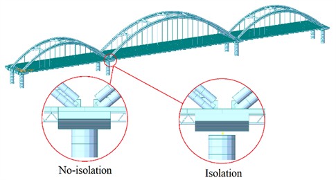
Table 2First five frequencies and modes
Order | Non-isolated | Isolation | ||||
Frequency (Hz) | Mode shape diagram | Mode shape | Frequency (Hz) | Mode shape diagram | Mode shape | |
First | 0.269 |  | Lateral displacement of the middle arch rib | 0.220 |  | Lateral displacement of the middle arch rib |
Second | 0.472 |  | Lateral displacement of the side arch ribs | 0.244 |  | Longitudinal movement of the arch rib and bridge deck system |
Third | 0.472 | 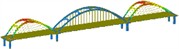 | Lateral displacement of the side arch ribs | 0.296 |  | Lateral displacement of the middle arch rib |
Fourth | 0.736 |  | Vertical vibration of the middle arch rib and deck system | 0.297 |  | Lateral displacement of the side arch ribs |
Fifth | 0.737 |  | Middle arch rib and bridge deck system torsion | 0.486 | 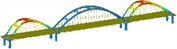 | Lateral displacement of the side arch ribs |
4. Seismic response analysis
4.1. Seismic wave selection and excitation direction
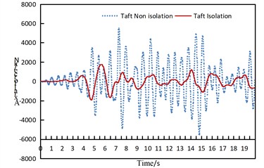
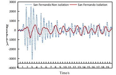
This bridge is located in an area with a seismic fortification intensity of 8 degrees (0.2 g), and the site category is Class Ⅱ. In this study, three actual seismic waves were selected, namely the El-Centro wave, Taft wave, and San Fernando wave. Considering the E1 seismic action, to ensure compatibility with the design response spectrum specified in the seismic code and facilitate comparative analysis, the maximum horizontal amplitude was uniformly adjusted to 0.122 g, and the maximum vertical amplitude was uniformly adjusted to 0.079 g. The horizontal amplitude adjustment coefficients for the three seismic waves were set to 0.339, 0.784, and 0.387 respectively, while the vertical amplitude adjustment coefficients were 0.221, 0.509, and 0.251 respectively. The adjusted horizontal seismic waves are shown in Fig. 2.
The amplitude of the seismic waves is relatively large in the first 20 seconds; moreover, to save calculation time, the duration of the seismic action was set to only the first 20 seconds. The seismic action was applied along the longitudinal, transverse, and vertical directions of the two models respectively.
Fig. 2Seismic waves
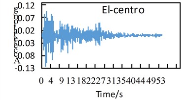
a) Adjusted El-centro wave
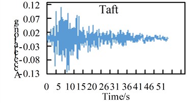
b) Adjusted Taft wave
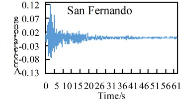
c) Adjusted San Fernando wave
4.2. Internal force response of arch ribs
Due to space limitations, only the variation of partial internal forces along the arch rib and the time-history response of the two structural models are compared and analyzed here. For specific details, please refer to Figs. 3-7.
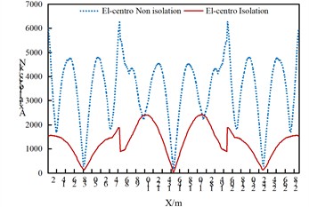
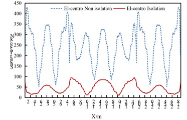
As can be seen from Fig. 3, under the seismic action along the longitudinal direction of the bridge:
(1) The axial force of the arch rib in the isolated structure decreases significantly, which indicates that the isolated structure can effectively reduce the axial force of the arch rib under the seismic action along the longitudinal direction of the bridge.
(2) For the non-isolated structure, the axial force of the arch rib is the largest at the arch foot, and also relatively large at the approximate 3/8 and 5/8 positions. Attention should be paid to strengthening the corresponding parts, while the axial force is the smallest at the arch crown.
(3) Regarding the axial force of the arch rib in the isolated structure, the side arches are roughly in a “V” shape, and the middle arch is roughly in an inverted “W” shape. That is to say, the maximum axial force of the side arches is at the arch foot, and the maximum axial force of the middle arch is at the 1/4 and 3/4 positions of the arch rib. The parts to be strengthened for the arch ribs of the isolated structure and the non-isolated structure should be treated differently.
Fig. 3Comparison of axial forces of arch ribs of non isolated and isolation structures under uniform excitation along the bridge direction
a) El-Centro
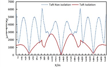
b) Taft
c) San Fernando
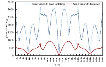
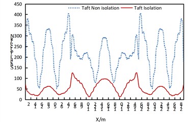
Fig. 4Comparison of axial forces of arch ribs of non isolated and isolation structures under uniform transverse excitation
a) El-Centro
b) Taft
c) San Fernando
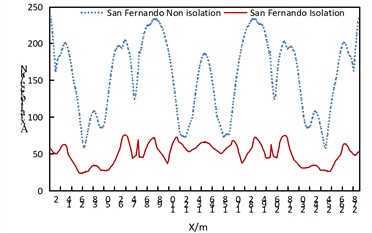
As can be obtained from Fig. 4, under the uniform excitation in the transverse direction of the bridge:
(1) The axial force of the arch rib in the isolated structure decreases significantly.
(2) For the non-isolated structure, the axial force of the arch rib is the largest at the arch feet on both sides of the side arches, and also relatively large at the position approximately 5/8 of the side arches near the middle arch. The axial force distribution of the middle arch is roughly in a “W” shape, with the maximum values at the positions approximately 3/8 and 5/8 of the arch rib. Attention should be paid to strengthening the corresponding parts.
(3) The axial force of the arch rib in the isolated structure shows a wavy distribution.
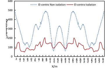
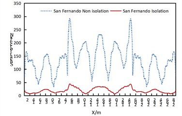
Fig. 5Comparison of axial forces of arch ribs of non isolated and isolation structures under vertical uniform excitation
a) El-Centro
b) Taft
c) San Fernando
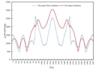
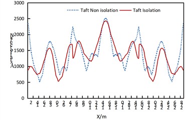
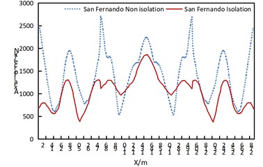
As can be obtained from Fig. 5, under vertical uniform excitation:
(1) For the isolated structure, the axial force at the arch feet decreases under the action of the Taft wave and San Fernando wave, while the seismic isolation effect is not obvious at other parts. Under the excitation of the El-Centro seismic wave, the axial force of the middle arch basically shows an increasing trend, the axial force at the arch feet decreases slightly; the axial force at the arch feet of the side arches near the middle arch increases, while the axial force at the arch feet on both sides of the side arches decreases.
(2) The axial force of the arch ribs of the side arches and middle arch of both structures roughly presents a “W” shape.
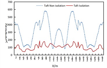
Fig. 6 reveals the following observations under longitudinal seismic excitation:
(1) The isolated structure demonstrates significant shear force reduction with relatively uniform distribution along the arch rib.
(2) The non-isolated structure exhibits substantial shear force fluctuations along the arch rib, characterized by a sawtooth pattern.
(3) The isolated structure maintains consistent shear force distribution along the arch rib, with both side and central arches displaying a characteristic “W”-shaped profile.
Fig. 6Comparison of arch rib shear of non isolated and isolation structures under uniform excitation along the bridge direction
a) El-Centro
b) Taft
c) San Fernando
Fig. 7Time history response diagram of side arch and arch foot axial force of non isolated and isolation structure under uniform excitation along the bridge direction
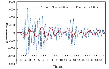
a) El-Centro
b) Taft
c) San Fernando
As can be seen from Fig. 7, under the seismic action along the longitudinal direction of the bridge, the axial force at the arch feet of the side arches presents the following characteristics:
(1) For the non-isolated structure, under the excitation of the El-Centro wave and San Fernando wave, the axial force decays rapidly and decreases significantly after 6-7 seconds. A secondary small peak of the axial force appears again between 11-13 seconds when subjected to the El-Centro wave. When subjected to the Taft wave, the axial force remains relatively stable from 0 to 4 seconds, while it maintains a relatively large response from 4 to 16 seconds. It is evident that the structural responses induced by different seismic waves are significantly different.
(2) For the isolated structure, under the action of the three seismic waves, the axial force of the arch rib decreases significantly and remains relatively stable in all cases.
4.3. Arch rib displacement response
From the comparison of arch rib displacements, the following conclusions can be drawn:
(1) Under the seismic action along the longitudinal and transverse directions of the bridge, the arch rib displacement of the isolated model increases; under vertical seismic excitation, the difference in arch rib displacement between the two models is not obvious.
(2) Under the seismic action along the longitudinal direction of the bridge, the displacement of both structural models is the largest at the 1/4 arch rib position; under the seismic action along the transverse direction of the bridge, the displacement of both structural models is the largest at the arch crown position.
(3) The arch rib displacement under the uniform seismic excitation in the transverse direction of the bridge is larger than that under the uniform seismic excitation in the longitudinal and vertical directions of the bridge.
Fig. 8Comparison of arch rib displacements
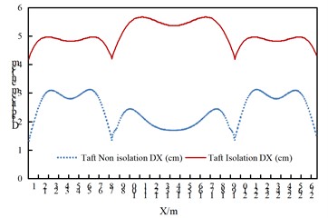
a) Displacement DX of arch rib under consistent excitation along the bridge longitudinal direction of the Taft wave
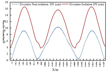
b) Displacement DY of the arch rib under transverse uniform excitation of the El-Centro wave
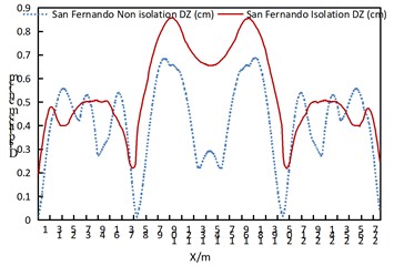
c) Displacement DZ of the arch rib vertical consistent excitation of the San Fernando wave
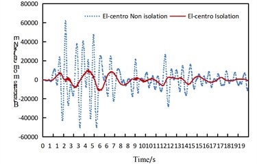
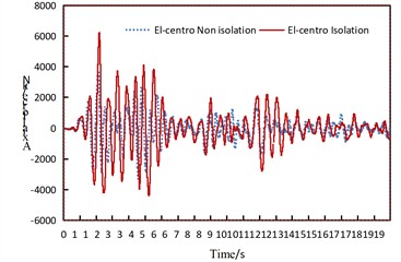
4.4. Speed response of arch ribs
From the comparison of arch rib velocities, the following observations can be made:
(1) The maximum velocity of the arch rib in the isolated structure is slightly greater than that in the non-isolated structure, and it occurs slightly later than that in the non-isolated structure.
(2) The variation frequency of the arch rib velocity in the isolated structure is lower than that in the non-isolated structure.
Fig. 9Time history comparison of arch rib velocity
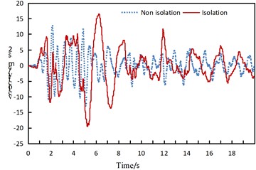
a) Ventral velocity in the -direction under consistent longitudinal excitation of the El-Centro wave
b) Vault velocity in the -direction under consistent transverse excitation of the Taft wave
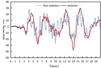
4.5. Internal force response of piers
The comparison of the maximum internal forces of piers is shown in Table 3 and Fig. 10.
Fig. 10Time history comparison of internal force at pier bottom
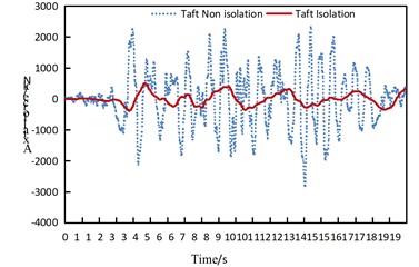
a) Time history of pier base axial force under transverse uniform excitation of Taft wave
b) Time history of pier base bending moment My under consistent longitudinal excitation of El-Centro wave
c) Time history of pier base axial force under vertical consistent excitation of El-Centro wave
It can be concluded that: under longitudinal seismic action, the average seismic reduction rates of the maximum axial force and bending moment of the piers are 86.0 % and 82.7 % respectively; under transverse seismic action, the average seismic reduction rates of the maximum axial force and bending moment of the piers are 84.1 % and 58.1 % respectively; under longitudinal seismic action, the average seismic reduction rates of the maximum axial force and bending moment of the piers are –16.1 % and 72.2 % respectively. Only when the El-Centro seismic wave acts along the vertical direction, the maximum axial force of the pier in the isolated structure model increases, while it decreases in all other cases.
Table 3Comparison of maximum internal force of piers
Seismic wave | Model | Along the bridge | Transverse direction of bridge | Vertical direction of the bridge | |||||||||
Axial force (kN) | Reduction rate | Bending moment (kN·m) | Reduction rate | Axial force (kN) | Reduction rate | Bending moment (kN·m) | Reduction rate | Axial force (kN) | Reduction rate | Bending moment (kN·m) | Reduction rate | ||
El-centro | Non-isolated | 2076 | 88.8 % | 61996 | 81.5 % | 2597 | 80.7 % | 22529 | 49.9 % | 3647 | –71.7 % | 4837 | 59.9 % |
Isolated | 233 | 11440 | 502 | 11292 | 6262 | 1939 | |||||||
Taft | Non-isolated | 1668 | 81.5 % | 49826 | 79.9 % | 2900 | 81.3 % | 24152 | 57.0 % | 3485 | 3.4 % | 4627 | 74.5 % |
Isolated | 308 | 10006 | 543 | 10381 | 3365 | 1180 | |||||||
San Fernando | Non-isolated | 1033 | 87.7 % | 31970 | 86.6 % | 1766 | 90.4 % | 14537 | 67.4 % | 3779 | 19.8 % | 6409 | 82.1 % |
Isolated | 127 | 4299 | 170 | 4741 | 3029 | 1147 | |||||||
4.6. Absolute acceleration response of bridge deck
The maximum absolute acceleration of the deck is shown in Table 4. It can be concluded that: under longitudinal seismic action, the average seismic reduction rates of the maximum absolute acceleration of the deck in the longitudinal and vertical directions are 81.2 % and 90.1 % respectively; under transverse seismic action, the average seismic reduction rates of the maximum absolute acceleration of the deck in the transverse and vertical directions are 86.0 % and 81.8 % respectively; under longitudinal seismic action, the average seismic reduction rates of the maximum absolute acceleration of the deck in the longitudinal and vertical directions are –20.9 % and 12.9 % respectively. Under vertical seismic action, the longitudinal absolute acceleration of the isolated structure increases; in addition, under the vertical action of the El-centro wave, the vertical absolute acceleration also increases.
Table 4Comparison of maximum absolute acceleration of bridge deck
Seismic wave | Model | Along the bridge | Transverse direction of bridge | Vertical direction of the bridge | |||||||||
DX (cm/s2) | Reduction rate | DZ (cm/s2) | Reduction rate | DY (cm/s2) | Reduction rate | DZ (cm/s2) | Reduction rate | DX (cm/s2) | Reduction rate | DZ (cm/s2) | Reduction rate | ||
El-Centro | Non-isolated | 213.58 | 81.8 % | 401.28 | 91.2 % | 371.44 | 83.8 % | 90.61 | 80.7 % | 57.84 | –7.5 % | 252.65 | –29.7 % |
Isolated | 38.96 | 35.44 | 60.16 | 17.45 | 62.15 | 327.73 | |||||||
Taft | Non-isolated | 144.06 | 77.3 % | 330.91 | 86.2 % | 475.13 | 87.1 % | 94.28 | 79.6 % | 41.17 | –46.9 % | 340.97 | 23.2 % |
Isolated | 32.68 | 45.67 | 61.15 | 19.21 | 60.49 | 262.03 | |||||||
San Fernando | Non-isolated | 104.16 | 84.6 % | 286.07 | 92.8 % | 230.77 | 87.0 % | 84.24 | 85.0 % | 57.01 | –8.3 % | 391.27 | 45.1 % |
Isolated | 16.04 | 20.56 | 30.05 | 12.61 | 61.73 | 214.71 | |||||||
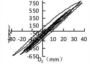
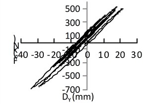
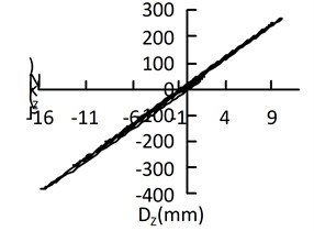
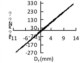
4.7. Support hysteresis curve
It is relatively difficult to accurately establish a hysteretic model for lead-rubber bearings, so the software modifies the hysteretic curve into a bilinear model. The hysteretic curves of the isolation bearings on the side piers under different excitations are shown in Fig. 11.
Fig. 11Hysteretic curve of isolation bearing under uniform excitation
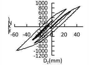
a) El-centro along the bridge
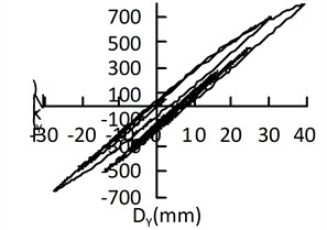
b) El-centro transverse direction of bridge
c) Taft along the bridge
d) Taft transverse direction of bridge
e) San Fernando along the bridge
f) San Fernando transverse direction of bridge
As can be seen from Fig. 11, when the El-Centro wave and Taft wave act along the longitudinal direction of the bridge, their hysteretic curves are somewhat fuller than those when the corresponding waves act along the transverse direction of the bridge; there is no obvious difference in the fullness of the hysteretic curves of the San Fernando wave under excitation along the longitudinal and transverse directions of the bridge. The hysteretic curves exhibit different shapes under the excitation of the three waves. It can be concluded that uniform excitations of different seismic waves in different directions result in different hysteretic curves, which indicates that seismic waves and the direction of seismic action affect the shape of the hysteretic curves of lead-rubber bearings.
5. Conclusions
From the above comparative analysis, the following conclusions can be drawn:
1) The differences in fundamental frequency and mode shape between the non-isolated structure and the isolated structure are not obvious, but the differences in frequencies and mode shapes of the other orders are relatively significant.
2) Under the seismic action along the longitudinal and transverse directions of the bridge, the internal force of the arch rib in the isolated structure decreases significantly, showing a remarkable seismic isolation effect; under vertical seismic action, the seismic isolation effect is not obvious, and an increase in internal force may even occur. The axial force of the arch rib caused by uniform excitation along the longitudinal direction of the bridge is greater than that caused by uniform excitation along the transverse direction. For the non-isolated structure, the time-history responses of internal forces under the excitation of different seismic waves are significantly different, while the isolated structure shows relatively stable responses in all cases. Under longitudinal and transverse seismic excitation, the displacement of the arch rib in the isolated structure increases; under vertical seismic excitation, there is no obvious difference in arch rib displacement between the two models.
3) Regarding the main internal forces of the piers: except that the maximum axial force of the isolated structure model increases when the El-Centro seismic wave acts vertically, all other internal forces decrease significantly. For the maximum absolute acceleration of the deck: except that the longitudinal absolute acceleration of the isolated structure increases under vertical uniform excitation and the vertical absolute acceleration increases under the vertical excitation of the El-centro wave, all other accelerations decrease significantly.
Under seismic excitation along both the longitudinal and transverse directions of the bridge, Lead-Rubber Bearings (LRBs) significantly reduced the internal forces in the arch ribs by 60 %-80 % and decreased the deck acceleration by 70 %-90 % in both directions, demonstrating effective seismic isolation performance.
Research has been conducted on the seismic response of multi-span through-type concrete-filled steel tube (CFST) arch bridges under uniform excitation. However, further investigation is required for non-uniform excitation scenarios that account for factors such as the traveling wave effect, coherence effect, and site effect.
References
-
Y. Liu et al., “Research on vibration reduction of high-speed railway flexible arch bridge with long-span continuous steel truss beam,” (in Chinese), Chinese Journal of Applied Mechanics, Vol. 36, No. 3, pp. 666–673, 2019, https://doi.org/10.11776/cjam.36.03.c017
-
X. Yang, J. Li, and X.G. Lei, “Research on application of seismic isolation techniques to multiple and large-span continuous girder bridge,” (in Chinese), China Journal of Highway and Transport, Vol. 23, No. 6, pp. 58–65, 2010, https://doi.org/10.19721/j.cnki.1001-7372.2010.06.009
-
Y. Mao, Li, and Jianzhong, “Analysis of seismic mitigation mechanism and effect on longitudinal direction of long-span continuous bridge,” (in Chinese), Journal of Tongji University (Natural Science Edition), Vol. 42, No. 2, pp. 185–191, 2016, https://doi.org/10.11908/j.issn.0253-374x.2016.02.004
-
X. Xia, L. Cui, and X. Chen, “Study of application of seismic isolation techniques for long span and long unit continuous beam bridge,” Bridge Construction, Vol. 45, No. 4, pp. 39–45, Apr. 2015.
-
Y. Li and C. Li, “Influence of seismic response parameters on seismically-isolated girder bridge under near-fault ground motions,” Bridge Construction, Vol. 49, No. 5, pp. 68–72, May 2019.
-
Z. Zhang, Y. Shi, and H. Qin, “Analysis on the seismic responses of isolated skew bridges considering the ambient temperature effect and lead core heating of LRB under near-fault ground motions,” (in Chinese), Journal of Vibration and Shock, Vol. 41, No. 14, pp. 172–180, 2022, https://doi.org/10.13465/j.cnki.jvs.2022.14.024
-
G. Zhao et al., “Analysis on seismic response of frictional pendulum isolated bridges limited by rotational mass friction damper,” (in Chinese), China Civil Engineening Journal, Vol. 56, No. 2, pp. 46–57, 2023, https://doi.org/10.15951/j.tmgcxb.2022.0403
-
X. Liang, Q. Li, and C. Su, “Study on the overall scheme and isolation of the main bridge of a sea-crossing bridge,” (in Chinese), Journal of Vibration and Shock, Vol. 38, No. 9, pp. 252–259, 2019, https://doi.org/10.13465/j.cnki.jvs.2019.09.033
-
C. Shao et al., “Optimization of seismic isolation bearing scheme of RC long span soft arch bridge under near-field and far-field ground motions,” (in Chinese), Journal of Southwest Jiaotong University, Vol. 59, No. 3, pp. 615–626, 2024, https://doi.org/10.3969/j.issn.0258-2724.20220122
-
J. Liu, “Research on seismic isolation design of multi-span rigid frame-continuous girder bridge in high seismic intensity area,” Journal of Railway Engineering Society, No. 5, pp. 40–46, May 2013.
-
X. Zhuang, C. Shen, and J. Jin, “Experimental study on mechanical property of high damping rubber bearing for bridge,” (in Chinese), Earthquake Engineering and Engineering Dynamics, No. 5, pp. 208–212, 2006, https://doi.org/10.13197/j.eeev.2006.05.034
-
T. Peng, X. Yu, Z. Wang, and L. Han, “Study of the seismic performance of expansion double spherical seismic isolation bearings for continuous girder bridges,” (in Chinese), Earthquake Engineering and Engineering Vibration, Vol. 11, No. 2, pp. 163–172, Jul. 2012, https://doi.org/10.1007/s11803-012-0107-3
-
L. Xu et al., “Dynamic response analysis of long-span arch bridge under near-fault pulse seismic motion,” (in Chinese), Journal of Vibration and Shock, Vol. 43, No. 9, pp. 94–104, 2024, https://doi.org/10.13465/j.cnki.jvs.2024.09.012
-
Y. Li, X. Ren, and W. Yan, “Shaking table study on a three-span irregular CFST arch bridge model,” (in Chinese), Journal of Beijing University of Technology, Vol. 38, No. 9, pp. 1302–1309, Sep. 2012.
-
L. Xu et al., “Effects of near-fault and non-near-fault ground motion on seismic response of arch bridge:a comparative study based on Meta-analysis,” (in Chinese), Journal of Vibration and Shock, Vol. 44, No. 17, pp. 124–135, 2025, https://doi.org/10.13465/j.cnki.jvs.2025.17.013
-
Z. Li and Z. Li, “Seismic control of long-span arch bridge under spatially variable seismic excitation,” (in Chinese), Journal of Vibration and Shock, No. 7, pp. 83–86, 2008, https://doi.org/10.13465/j.cnki.jvs.2008.07.032
About this article

This research was funded by the Fundamental Research Funds for the Central Universities (31920230177); Key Laboratory of Green Engineering Materials and Low-carbon Construction, Gansu Province; Industrial Research Institute of Prefabricated Buildings and Energy-Saving Materials.
The datasets generated during and/or analyzed during the current study are available from the corresponding author on reasonable request.
The authors declare that they have no conflict of interest.
