Abstract
A distributed, low-order and highly efficient strapdown navigation algorithm is developed to estimate the real flight parameters for flight control system. Firstly, the attitude estimation Kalman filter is designed according to the relationship between angular and angular rate. Then, the measured angular rate is compensated by solving the drift noise of gyro. Furthermore, the accuracy of attitude is improved by compensating the accelerometer of the rigid body from differential velocity of GPS. Secondly, the improved attitude is used as an input into the filter algorithms of velocity and position by using the concept of distributed Kalman filter, which reducing the order of Kalman filter effectively. The velocity and position filter algorithms, which provide smooth feedback parameters for control system, are developed based on the rigid body dynamic equations and GPS parameters. Finally, the numerical simulation indicates that the attitude provided by attitude Kalman filter is of high accuracy in flight condition, and the performance of the attitude velocity and position algorithms are verified by flight tests of a small unmanned tiltrotor.
1. Introduction
Flight control system and strapdown inertial navigation system are the key technologies of unmanned aerial vehicle (UAV). A properly designed flight control law and control structure can improve the stability and flight qualities of UAV. Because of that solving control law is based on the flight parameters from the onboard strapdown inertial navigation system, so the algorithm of strapdown inertial navigation is taken into consideration increasingly. The traditional platform-style inertial navigation system is difficult to be applied in UAV system due to the complex structure and cost-expensive, while the MEMS-based strapdown inertial navigation system with small-size, light-weight and low-cost improve the accuracy of flight control parameters by designing multi-sensors fusion algorithms [1-5]. Literature [6] described a linear Kalman filter by using differential equation of orientation cosine matrix with the state vector constructed by the measurements of tri-axial magnetometers and tri-axial accelerometers, which improved the computation cost effectively. Kim et al.[7] presented a real-time quaternion-based attitude estimation system, of which the state equation was developed according to the relationship between quaternion and attitude angular. The measurement models of those algorithms were derived from the onboard accelerometers, which lead to high deviation of attitude in accelerated flight condition. Bijker [8] proposed two low-order extended Kalman filters for estimating the attitude by using MEMS gyro, accelerometer and magnetometer, meanwhile, the velocity and position estimation algorithms were given by using a loosely integrated GPS receiver. The nonlinear algorithms were deduced by the quaternion kinematics equation, which should be linearized to get attitude with large computational expense, and the rounding error would be introduced in the process of linearization. In this paper, a distributed and low-order GPS/SINS algorithm for UAV flight control system is designed. The attitude estimation Kalman filter is developed according to angular rate integration. The drift noise of gyro is solved and compensated by state matrix in real time, and the integrated error of gyro is eliminated effectively in recursion. The differential velocity from GPS is used to improve attitude accuracy in flight condition. On the basis of attitude estimation, a cascaded concept is utilized in designing velocity and position algorithms to reduce the filter order effectively. The reliability and practicability of presented algorithms are verified by flight tests of a small UAV.
2. GPS/SINS algorithm structure
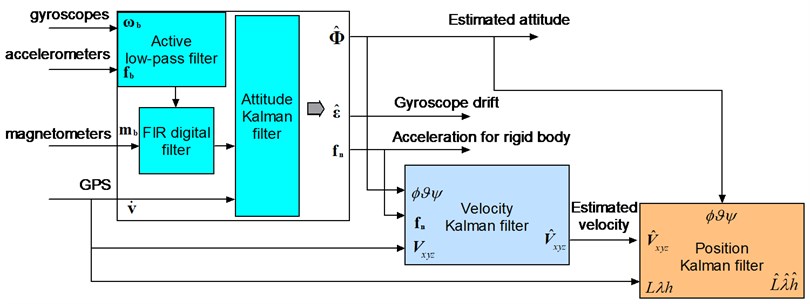
The series-connected structure of the algorithm is shown in Fig. 1. The original analog datum, collected from the MEMS gyro and accelerometer, are filtered through the onboard active low-pass filter to reduce the high frequency noise. The digital signals from the A/D are again filtered by FIR before entering the attitude Kalman filter. The body high-frequency vibration and noise in the circuit are reduced greatly. The differential velocity from GPS is used to compensate the continuous acceleration in order to improve the accuracy of the measured attitude. With the attitude angle as an input, the velocity estimation algorithm is developed according to the rigid body dynamics equations, and the position algorithm is also deduced by the relations between velocity and position.
Fig. 1GPS/SINS algorithm architecture
3. Algorithm of attitude determination
Attitude determination system is a core technology of the strapdown inertial navigation system for UAV. In this paper, a low-order Kalman filter is used for solving attitude which is derived from the integration of the angular rate and the drift characteristics of the rate gyro is estimated in each iteration in real time.
3.1. Measurement model of attitude
The measured attitude can be obtained from onboard accelerometer and magnetometer, so the measured noise of the measurement system depends on the features of accelerometer and magnetometer. Since the accelerometer simultaneously measures the gravity and the rigid body acceleration, the slight difference between the measured attitude from accelerometer and the actual flight attitude comes up under speed-up flight conditions. The differential velocity from GPS compensates the signal from accelerometer and improves the accuracy of measured attitude in flight condition, so the compensated specific force can be given as:
where are the differential velocities from GPS in earth frame, represent the measured specific force from body accelerations, and are the compensated specific force, is the attitude transformation matrix from earth to body frame as follows:
where stand for roll, pitch and yaw angles of the UAV respectively. The measured attitude of roll and pitch angles with the compensated specific force in the body frame are obtained as:
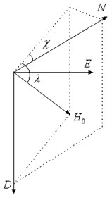
The Earth’s magnetic field is defined according to its orientation relative to the geographic frame, which known as the angle of magnetic declination and dip angle relative to horizontal [9], as indicates in Fig. 2.
Fig. 2Distribution of Earth’s magnetic field
The magnetic field is mapped into the horizontal component () and vertical component (), and then the magnetic measurements in body sensitive axis are:
where is the magnetic heading angle. Defining:
Therefore, the measured magnetic heading angle is constructed as:
where are the components of body frame magnetic filed, which measured by tri-axial magnetometers, respectively. Then the measured yaw angle as below:
3.2. Process model of attitude
The measured errors of tri-axial angular rate gyros usually contain determinate error and uncertain error. The determinate error can be compensated by sensors calibration. According to the statistical probability, the uncertain error model of MEMS gyro mainly contains random constant, first order Markov process and white noise. In order to reduce the order of the Kalman filter, the drift feature of rate gyro consists of the random constant and white noise, and the error model is given by:
where is random constant, is white noise. The measurement equations of the tri-axial angular rate gyros are expressed as:
where are the measured signals from gyros, are the angular rates of the UAV. The state equations are obtained in continuous domain:
in which, are process attitudes, are initial attitudes. Defining as the system sample time, the discretized form of Eq. (10) yields:
where state vector , state transition matrix , control matrix , control input vector , noise matrix and process noise vector are defined as:
According to the relationship between the measured attitude and process attitude, the output equation of the attitude Kalman filter is:
where is the Gaussian white noise series, and the output matrix is:
4. Algorithms for estimation of velocity and position
4.1. Algorithm design for velocity
At present, accelerometer, GPS and differential pressure sensor are usually used to measure velocity of the UAV. In this paper, the accelerometer and GPS are used for designing velocity Kalman filter, and the process equations in terms of the rigid dynamic equations are expressed as:
where are body velocities, is mass, are the forces acting on the UAV. The gravity and external forces produce acceleration, which is measured by onboard accelerometer. The pseudo-acceleration caused by attitude should be compensated in the process equations of velocity estimation, so, the measurement equations can be written as:
where are first order Markov processes of tri-axial accelerometers, are Gaussian white noise. Substituting Eq. (17) into Eq. (16), the state equations can be given by:
where are the driver noise of first order Markov process, are the autocorrelation coefficients. The velocities from GPS are in the earth frame, which should convert to the body frame by using attitude matrix. Then the output equation of the velocity estimation is given:
where are measured velocity noise of GPS.
4.2. Algorithm design for position
According to the cascade filter designing concept, the attitude and velocity are used as control input of the position estimation system. The filtered velocity in body frame transforms into the earth frame as follows:
where is the transpose of , is the estimated velocity vector in the body frame, and is the velocity vector in earth frame. The former equation discretizes as:
where . By expanding Eq. (21) in matrix form as:
where are the Cartesian coordinate components in earth frame which have to turn into the more commonly used geodetic-mapping coordinate [10]. As a consequence, the output equation of the position estimation is obtained as:
where are latitude, longitude and vertical position, and are measured position noise of GPS.
5. Numerical simulation of attitude estimation
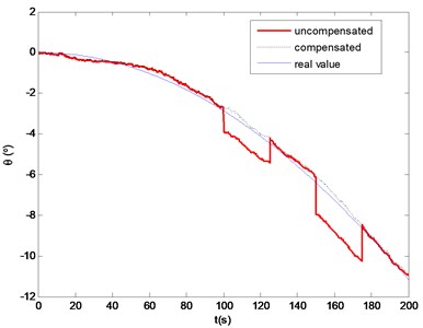
Attitude estimation system could measure tri-axial angular rates, attitudes and heading parameters in real time, which corresponding to damping control loop and attitude control loop of flight control system for the UAV respectively. The accuracy of attitude estimation affects the stability of flight control system, and as the inner loop of the cascaded Kalman filter, it also influences the accuracy of velocity and position estimation. Therefore, the performance of the attitude estimation is verified in numerical simulation. The control plant is described by using six-degree rigid body equations of motion. In this simulation, the update rate of the attitude estimation system is 20 Hz, the measured noise covariance of MEMS gyro is 0.05 o/s, the measured noise of accelerometer is about 10 mg, and the GPS update rate is 4 Hz. Figure 3 shows the differences between the actual attitudes and the filter outputs, with roll and pitch moments apply on the control plant. The designed algorithm is satisfied to track the target movement in real time. When the controlled plant is applied on continuous nose-down torque, and two 25 s continuous longitudinal forces, as shown in Fig. 4, the simulation results indicate that the pitch angle of controlled plant decreases gradually. At 100 s, the onboard accelerometer measures the rigid body motion and the gravity component simultaneously, which results in a constant deviation pitch angle without GPS compensation. After the on-line acceleration compensation, the output from filter has a good accuracy of pitch angle in the flight condition.
6. Low-cost GPS/SINS hardware design
To demonstrate the effectiveness of the proposed algorithms, the onboard avionics of the GPS/SINS is developed and the prototype system is designed according to payload and performance requirements of the small tiltrotor. Figure 5 shows the block diagram of onboard GPS/SINS, which contains power supplier, micro-inertial measurement unit (MIMU) and navigation unit.
Fig. 3Attitude outputs under action of moments
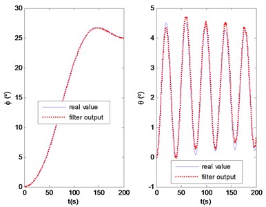
Fig. 4Pitch angle output in flight condition
The main consideration in the power suppler design is to meet the whole experimental requirements and total system safety. Based on the detail power consumptions of the onboard avionics, the lithium–polymer battery with 2200 mAh capacity, 25 C discharge rate, 185 g weight and 11.1 V output voltage is selected, and the voltage is converted to 5 V by a DC/DC model.
The MIMU plays an important role in collecting signals from MEMS sensors, which include angular rate, acceleration and magnetic filed. The collecting process is complemented on an 8-bit Atmel ATmega16 micro-controller which utilizes six AD channels to acquire the analog digitals from gyro and accelerometer, also collects digital signal from magnetometer via standard SPI interface. In real environment, the outputs of MIMU often suffer from large sensor noise. In order to reduce the initial noise, the collected signals are preprocessed by low-pass filter, packaged and sent to the navigation unit via a standard RS232 serial port.
ARM2440 is used to collect datum from MIMU and GPS, execute attitude velocity and position algorithms, carry out control laws and drive actuators. It clocks at 533 MHz and supports various peripherals.
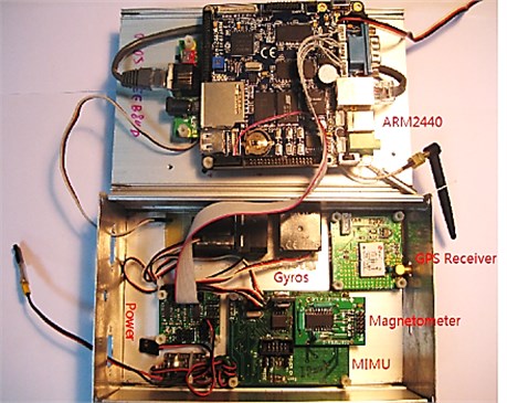
The specific hardware components in the airborne prototype are shown in Fig. 6. A properly sized aluminum box is designed to contain the onboard hardware components and protect them from being contaminated.
Fig. 5GPS/SINS block diagram
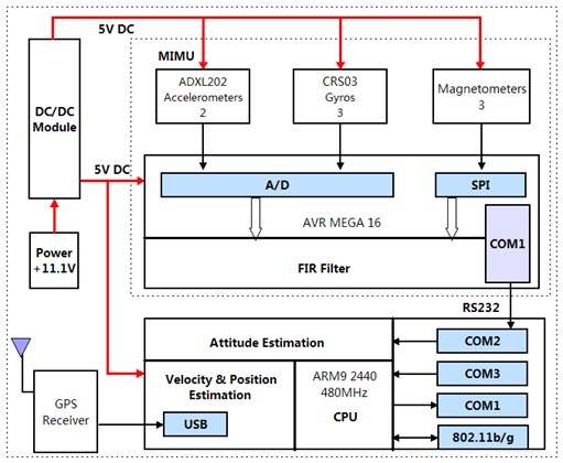
Fig. 6The onboard prototype of the GPS/SINS
The onboard avionics must be small, light and cost-effective enough for installing into the small tiltrotor aircraft. Table 1 lists the specifications of the MEMS sensors.
Table 1Sensors specifications
Item | Rate gyros | Accelerometers | Magnetometers |
Range | ± 100 deg/sec | ±2 g | ±550 µT |
Bias initial error | ± 60 mv | - | - |
No linear | < 0.5 % | < 0.2 % | < 1 % |
Scale factor | 20 mv/deg/sec | 312 mv/g | - |
Resolution | 0.05 deg/sec | 5 mg | 0.0055 µT |
Bandwidth | > 10 Hz | 500 Hz | 175 KHz |
Power consumption | (4.75-5.25 V)/50 mA | (3-5.25 V)/0.6 mA | (2.2-5.25 V)/0.6 mA |
Weigh | 25 g | 0.9 g | 0.3 g |
7. Flight validation
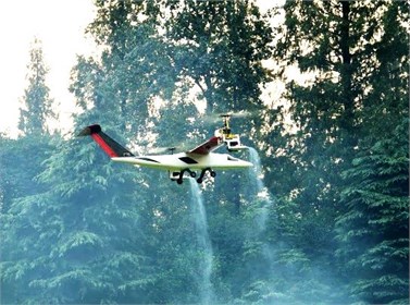
Experiments are performed on a small unmanned tiltrotor to validate the stability of the proposed algorithms. The attitude filter update rate is 100 Hz and GPS update rate is 4 Hz. Fig. 7 shows the small unmanned tiltrotor in flight tests, which consists of rotorcraft, wing, fuselage, engine nacelle, horizontal and vertical tails, driving mechanism, flight control system, strapdown inertial navigation system and landing gear et al.
Fig. 7Unmanned tiltrotor aircraft in the flight tests
7.1. Hover tests
The hover flight is the major flight mode of the small unmanned tiltrotor. The results are shown in Figs. 8-11. Fig. 8 shows the measured outputs of three-axis attitudes. It can be seen that the changing range in roll angle is within 6o, and the mean value is 2.86o. It indicates that the tiltrotor has a right constant deviation angle in trim flight condition. The range in pitch angle is from -4o to 4o, which indicates that the longitudinal axis of the tiltrotor is in horizon in trim condition. Due to the disturbance of wind, the range in yaw angle is larger than roll and pitch angles. Fig. 9 shows the three-axis velocities in hover. Fig. 10 and Fig. 11 show the horizontal position in north and east, in which the dotted lines represent the raw data from GPS, the solid lines represent the outputs from Kalman filter. It can be seen that the problem of position jumping and discontinuous is weakened, and the filter outputs are smoother than original data from GPS.
7.2. Full envelop flight tests
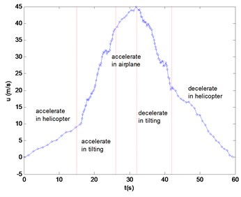
The small unmanned tiltrotor has three modes: helicopter, tilting and airplane flights. The airspeed varies dramatically during the tilting mode. The designed strapdown navigation system can measure flight parameters in the speed-up flight condition in real time. Fig. 12 shows the feature of the pitch angle in the full flight envelop. The pitch angle varies smoothly in the helicopter and airplane flight modes, while varying drastically in the tilting flight mode due to complex flight condition and the center of gravity shifting with tilting nacelle angle. Fig. 13 shows the characteristics of the forward velocity. The small tiltrotor speed up from the helicopter to tilting mode, the airspeed increases fastly with the nacelle tilting. After 10 seconds, the tiltrotor enters into the airplane mode, and continues speed up until 44 m/s. Then, the nacelle starts tilting from horizon to vertical position and the speed slows down into hover flight of helicopter mode finally. The flight tests results show that the attitude changes severely during the tilting mode in that the designed control law in helicopter mode is not quite robust in tilting mode for the flight environment changes significantly.
Fig. 8The tri-axial attitude angles in hover
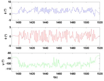
Fig. 9The tri-axial velocities in hover
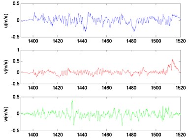
Fig. 10GPS vs KF output of north
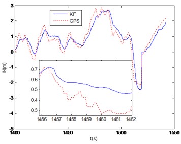
Fig. 11GPS vs KF output of east
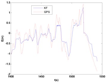
Fig. 12Pitch angle of the full envelop flight
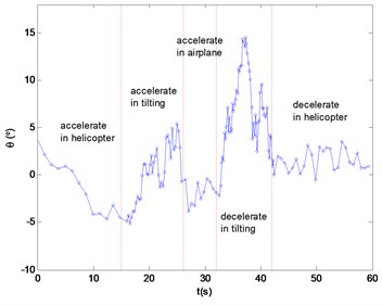
Fig. 13Forward speed of the full envelop flight
8. Conclusions
In this work, a whole set of navigation algorithm is developed for a small unmanned tiltrotor. The hardware of the onboard navigation system is designed and implemented successfully. A series of actual flight tests are conducted and the following conclusions could be given:
(1) The linear attitude estimation algorithm is designed on the basis of the integration of angular rate. The drift noise of gyro is solved in real time and compensated simultaneously, and the GPS is introduced to modify the accuracy of attitude estimation. The numerical simulation indicates a good performance of the measured attitude.
(2) The algorithms of the attitude, velocity and position for UAV adopt the cascaded linear Kalman filter, which fully use the output parameters from the former. The order of the full-state filter is reduced, and the computational expense is saved effectively.
(3) The onboard flight control law of the unmanned tiltrotor is implemented by utilizing the filtered data from strapdown inertial navigation system. The reliability of the proposed algorithms are verified under full flight envelop.
References
-
Wendel J., Meister O., Schlaile C., Trommer G. F. An integrated GPS/MEMS-IMU navigation system for an autonomous helicopter. Aerospace Science and Technology, Vol. 10, Issue 6, 2006, p. 527-533.
-
Wu Y. L., Wang T. M., Liang J. H., Wang C. L., Zhang C. Attitude estimation for small helicopter using extended Kalman filter. IEEE Conference on Robotics, Automation and Mechatronics, 2008, p. 577-581.
-
Jung D., Tsiotras P. Inertial attitude and position reference system development for a small UAV. Proceedings of 2007 AIAA Info Tech @ Aerospace Conference, 2007, p. 504-518.
-
Lee A. L., Kim J. H. 3-Dimensional pose sensor algorithm for humanoid robot. Control Engineering Practice, Vol. 18, Issue 10, 2010, p. 1173-1182.
-
Loebis D., Sutton R., Chudley J., Naeem W. Adaptive tuning of a Kalman filter via fuzzy logic for an intelligent AUV navigation system. Control Engineering Practice, Vol. 12, Issue 12, 2004, p. 1531-1539.
-
Zhu R., Sun D., Zhou Z. Y., Wang D. Q. A linear fusion algorithm for attitude determination using low cost MEMS-based sensors. Measurement, Vol. 40, Issue 3, 2007, p. 322-328.
-
Kim A., Golnaraghi M. F. A quaternion-based orientation estimation algorithm using an inertial measurement unit. Position Location and Navigation Symposium, PLANS, 2004, p. 268-272.
-
Bijker J., Steyn W. Kalman filter configurations for a low-cost loosely integrated inertial navigation system on an airship. Control Engineering Practice, Vol. 16, Issue 12, 2008, p. 1509-1518.
-
Titterton D. H., Weston J. L. Strapdown inertial navigation technology. 2nd Edition, London, Peter Peregrinus Ltd., 2004.
-
Drake S. P. Converting GPS coordinates (ϕλh) to navigation coordinates (ENU). Defence Science and Technology, DSTO-TN-0432, 2002, p. 1-7.
About this article

This work was supported by Natural Science Foundation of China (Grant No. 60705034), and a Project Funded by the Priority Academic Program Development of Jiangsu Higher Education Institutions.
