Abstract
This paper will present a wavelet-based algorithm for numerical integration. The contribution of the manuscript is that: 1) Define an integration wavelet, which is applied to the numerical integration and applicable for processing stationary vibration data; 2) The basic properties of integration wavelet, such as frequency response, convolution solution with zero mean, stability and ripple in pass-band are discussed, and the investigation results reveal the excellent properties of it; 3) The validity of presented approach is illustrated by numerical integration computation on angular oscillation of a pendulum. The theoretical research and engineering experiments show that the presented approach is valuable in the vibration signal estimation.
1. Introduction
As known, acceleration, velocity and displacement are regular physical measurements of vibration testing. Study the transformation among them is often encountered in many engineering problems. However, due to initial value, noise [1] and drift, a simple numerical integration algorithm is usually unstable for the engineering problem. Until now, the double integration real time processing on vibration acceleration signal were realized on hardware-based integrator in some vibration test.
Now, the new method of numerical integration is being studied for converting a measured history of acceleration data into a displacement data. There are two types of algorithm developed. One is by integrating the acceleration signal in the time domain. The typical case is an adaptive algorithm combined with band-limited multiple Fourier linear combiners (BMFLC) which can eliminate the problem of drifting in the numerical integration [2]. The other is by dividing the Fourier-transformed acceleration signal by the scale factor of and taking its inverse Fourier transform, such as an improved frequency domain method used in the reconstruct displacement signal from a measured acceleration response [3].
However, in recent years, the wavelet-based algorithm has been paid attention in integration numerical computation [4-6]. It can be applicable in the context of numerical approximation of integral equations, partial differential equations, ordinary differential equations [7-9] and signal identification [10]. Unfortunately, for unknown mathematic model and initial conditions for the vibration data in the engineering application, the given wavelet based algorithm in the literature [4-9] could not be directly employed in the vibration data estimation.
To solve the problem of numerical integration for vibration acceleration, the following work is done in this paper; 1) an integration wavelet is defined; 2) the numerical integration can be realized by the integration wavelet convoluting with the discrete time vibration signal; 3) the important properties of integration wavelet are discussed, and an experiment is given to demonstrate the validity and applicability of this new approach.
2. Combination wavelet
Consider a mother wavelet as a combination wavelet, and it is mathematically described in the combination of a series of harmonic components with a window [13]:
where is a window, and are start frequency and cut-off frequency respectively. is introducedfor cut down the ripple in pass-band of the frequency response .
can be regarded as the linear superposition of () wavelets. The Fourier transform pair of the combination wavelet is that:
can mathematically be explained a convolution result of a gate function with a window in the frequency domain while the frequency increment from to is set to 1. The wavelet is a pass-band filter with linear phase because of several cosine waves combination. The frequency response characteristic of the combination wavelet is shown in Fig. 1, it is obvious that the linear superposition of equal space wavelets is the foundation of filter with bandwidth. On the condition of limitation, the frequency response range of the combination wavelet can be expanded from 1 to 2, and the excellent frequency response characteristic has been constructed.
Fig. 1Schematic of a combination wavelet construction
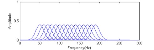
a) Numbers of equal space wavelets
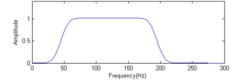
b) Linear superposition of equal space wavelets
3. Integration wavelet
Based on the combination wavelet in the Eq. (1), introduce an integration operation on it:
Let 1 and 2, the frequency increment be 1. Then, is defined as an integration wavelet. The range of frequency response of integration wavelet coves from 1 to 2. As stated as the above section, the action of window is to decay the pass-band ripple in the frequency response of integration wavelet.
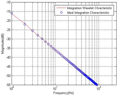
As shown in Fig. 2, that is a waveform of a discrete integration wavelet. The length of this integration wavelet 3679, the start frequency 1, the cut-off frequency 1839, and the frequency increment 1. is the Kaiser window [6] which is a one parameter family of window functions, where the parameter 1. The frequency response of integration wavelet is shown in Fig. 3, and it approaches to the one of an ideal integrator.
Fig. 2Waveform of integration wavelet hg(t) (The length of integration wavelet N= 3679, fL= 1 and fH= 1839)
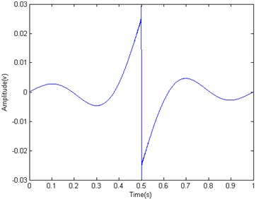
Fig. 3Frequency response of integration wavelet
4. Numerical integration
Because of the integration characteristic of the presented integration wavelet, when the integration wavelet convolutes with a vibration signal , the integration operation can be realized , and it is expressed as:
The numerical integration is done in the time domain through convoluting the integration wavelet with a time series.
In practice, the digital integration wavelet convolutes with a vibration acceleration measurement data , the estimation of vibration velocity can be obtained in the time domain. If one more convolution operation is carried out, the estimation of vibration displacement will be realized.
5. Characteristics of integration wavelet
5.1. Frequency response
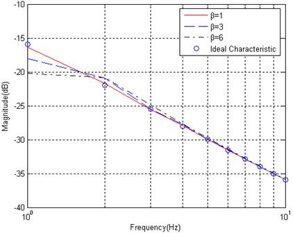
The parameter in the Kaiser window will affect the frequency response characteristic of the integration wavelet. When increases, the frequency response attenuates in the range of low frequency. The detail issue is illustrated in the frequency characteristics shown in Fig. 4. It is obvious that the attenuation happens in the frequency range of less than 2 Hz.
Fig. 4The parameter β in the Kaiser window affects the frequency response of an integration wavelet
5.2. Zero-mean and stability
Based on Eq. (3), the sine wave is selected in the construction of an integration wavelet, and the point of discrete time waveform is selected as odd number. Thus, the integration wavelet is an odd function, and the convolution operation on measurement data can remove the direct component. Therefore, the numerical integration is replaced by wavelet convolution operation, which is applicable for processing on a stationary acceleration signal. The advantages of wavelet-based integral algorithm as follows:
• No disturbance of initial value on numerical integration;
• Numerical integration result without direct component or tendency.
In additional, the integration wavelet is FIR construction, therefore, it is a kind of stable digital filter. Though the presented algorithm makes the computation loads little bit high in the application, the numerical integration on a time series will be stable.
5.3. Ripple in pass-band
When the integration wavelet convolutes with signal, the ripple in pass-band impliedly exists in the convolution result. In specially, the serious ripple will occur in the frequency around . If the convoluted signal with non-integer period, the ripple in pass-band will be remarkable in the convolution result. However, as the parameter increases in the Kaiser window, the ripple in pass-band will be decayed in the band edge. The effect of parameter in the Kaiser window on the ripple in pass-band is shown in Fig. 5, where the length of wavelet is 257, and the frequency parameter 1.
As motioned above, the quality of frequency response and the ripple in pass-band are dependent on selection of parameter in the Kaiser window. However, the selection of parameter is ambivalent for them. Therefore, it needs to balance the quality of frequency response and the ripple in pass-band in the selection of parameter dimension of the Kaiser window. In fact, is selected in the range of 1-4, both of the attenuation in the frequency response at 1 and the ripple in pass-band can be controlled in less than 30 % (–3 dB).
Fig. 5Parameter β in the Kaiser window affects pass-band ripple
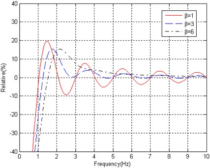
Fig. 6Different windows affect frequency response of integration wavelet
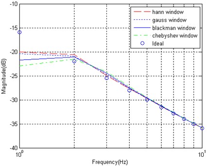
a) Different window functions affect frequency response of integration wavelet
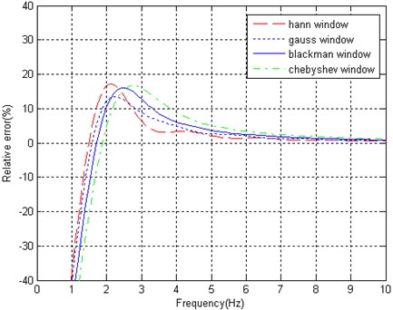
b) Different windows affect ripple in pass-band
5.4. Window function
Many window functions can be selected to construct the wavelet. The type of window will significantly influence the frequency response. Thus, it is necessary to observe the Kaiser window in comparison with the other window.
As shown in Fig. 6(a), the frequency responses in the range of lower frequency is sensitive to selection of window. It is obvious that the effect of Hanning, Gauss, Blackman and Chebyshev window on the frequency response characteristics are worse than Kaiser window ( 1-3).
The ripple in pass-band is also related to the selection of window. As shown in Fig. 6(b), although Hanning, Gauss, Blackman and Chebyshev window can improve the ripple in pass-band around frequency 1, the attenuation in the frequency response edge is still beyond 3 dB.
6. Example
An example is given to illustrate the superiority of the presented approach over existing techniques. A discrete time acceleration data is expressed as: , where 1 and 400 Hz and 1, 2, 3…, and the waveform is shown in Fig. 7. The result of two integrations realized by the presented integration wavelet is shown in Fig. 8. In contrast to integration performance, as shown in Fig. 9, the two integrations are directly done by the algorithm of numeric integration. It is obvious that there are a non-zero-mean value in an integral and a tendency in double integral because of unknown initial condition in the original algorithm, which is not adapted to process the problem of stationary vibration measurement data. However, the presented approach can overcome all defeats caused by the original algorithm of numerical integration.
Fig. 7A sinusoidal data x(n)=Asin(2πfn), where A= 1 and f= 400 Hz
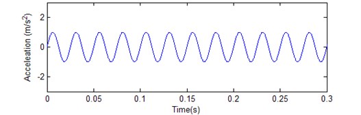
Fig. 8Result of two integrations realized by the presented integration wavelet
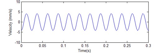
a) Velocity estimation
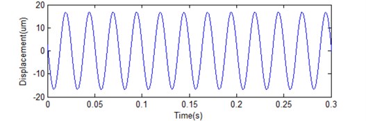
b) Displacement estimation
Fig. 9Result of two integrations realized by algorithm of numerical integration
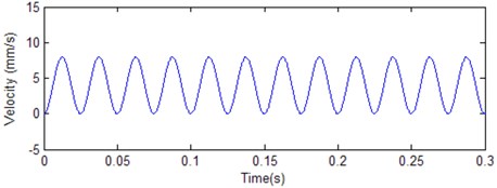
a) Velocity estimation
b) Displacement estimation
7. Application of signal detection
An application is to compare the angular oscillation wave estimation by the presented integration wavelet processing with a laser measured result. Fig. 10 is a schematic of angular oscillation detection with two accelerometers. Angular acceleration is measured from these two accelerometers on the rod pendulum. The angular acceleration is expressed as the form of signal combination:
The angular displacement is estimated by:
The double integrations are realized by applying the presented integration wavelet.
Fig. 10Principle of displacement estimation with two accelerometers
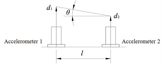
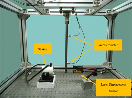
Fig. 11 is a scheme of measurement system of angular oscillation, and Fig. 12 is a photo of angular oscillation measurement. A sine signal from a signal generator is sent to a power amplifier (YE5871A), and drives a shaker (JZK-2) to excite the rod pendulum. Then the rod pendulum oscillates, and two accelerometers (CA-YD-186) pick up the acceleration signals at different locations. After data acquisition (ECON: MI-8008), the signal combination and numerical integration are processed by the presented approach. At the same time, a laser displacement sensor (Keyence: LK-G10, Resolution: 0.01 μm) gets the displacement of the end of rod, which is used to calibrate the angular oscillation. The angular displacement obtained by the laser measurement can be expressed as:
where is vibration displacement obtained by the laser, and is effective length from the detecting point to the rotating point.
Fig. 11Schematic of angular oscillation measurement
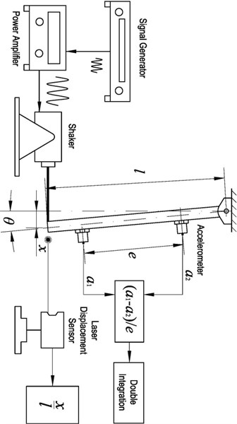
Fig. 12Photo of angular oscillation measurement
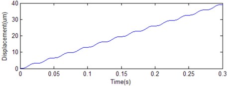
The angular oscillation is estimated by the integration wavelet convoluting with the angular acceleration signal, and the estimated result is illustrated in Fig. 13. The exciting frequency is 10 Hz in the vibration test. The RMS value of the angular oscillation wave obtained by the integration wavelet is 54.29 μrad, and another one measured by the laser displacement sensor is 54.41 μrad. The difference between them is about 0.22 %. The measured result by the presented method is highly agreement with the one by the laser measurement.
The presented approach was used to detect an angular oscillation of the optical payload in a satellite ground test, and the angular oscillation measurement data and its spectrum are shown in Fig. 14. The oscillation source of the optical payload came from a momentum wheel installed in the satellite body. The measurement result was used to assess the influence of the momentum wheel on the payload. The time series was obtained by double integrals on an angular acceleration oscillation off-line. The presented numerical integration can attain the angular measurement resolution less than 1 μrad in the engineering application. Besides, the problem of initial value is no longer to disturb the estimation of angular oscillation.
Fig. 13Angular acceleration measured by combination result of twin sensors
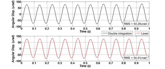
Fig. 14Angular displacement estimation on optical load in a satellite
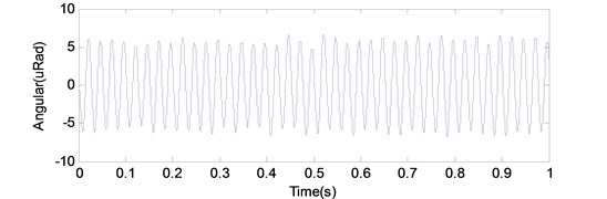
a) Angular oscillation time series
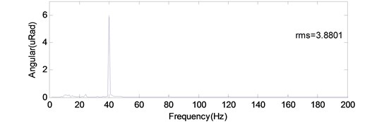
b) Spectrum analysis on angular oscillation
8. Conclusions
Based on a combination wavelet, an integration wavelet is defined, and it is used in the numerical integration adapted for processing a stationary vibration data. The estimations of vibration velocity and displacement are realized by convoluting the integration wavelet with a vibration acceleration data. The advantage of the presented integration wavelet is of high accuracy and good stability in the numerical integration operation on the condition of unknown initial condition. So it is recommended to be used in the numerical integration of stationary vibration acceleration measurement data.
References
-
Thong Y. K., et al. Numerical double integration of acceleration measurements in noise. Measurement, Vol. 36, 2004, p. 43-92.
-
U-Xuan Tan, et al. Estimation displacement of periodic motion with inertial sensor. IEEE Sensors Journal, Vol. 8, Issue 8, 2008, p. 1385-1388.
-
Sangbo Han Measuring displacement signal with an accelerometer. Journal of Mechanical Science and Technology, Vol. 24, Issue 6, 2010, p. 1329-1335.
-
Babolian E., Fattahzadeh F. Numerical computation method in solving integral equations by using Chebyshev wavelet operational matrix of integration. Applied Mathematics and Computation, Vol. 188, Issue 1, 2007, p. 1016-1022.
-
Hashish H., Behiry S. H., El-Shamy N. A. Numerical integration using wavelets. Applied Mathematics and Computation, Vol. 211, Issue 2, 2009, p. 480-487.
-
Siraj-ul-Islam, Imran Aziz, Fazal Haq A comparative study of numerical integration based on Haar wavelets and hybrid functions. Computers and Mathematics with Applications, Vol. 59, Issue 6, 2010, p. 2026-2036.
-
Lepik U. Numerical solution of evolution equations by the Haar wavelet method. Journal of Applied Mathematics and Computing, Vol. 185, 2007, p. 695-704.
-
Hariharan G., Kannan K. A comparative study of a haar wavelet method and a restrictive Taylor’s series method for solving convection-diffusion equations. International Journal for Computational Methods in Engineering Science and Mechanics, Vol. 11, Issue 4, 2010, p. 173-184.
-
Hariharan G., Kannan K., Sharma K. R. Haar wavelet method for solving Fisher’s equation. Applied Mathematics and Computation, Vol. 211, 2009, p. 284-292.
-
Hariharan G., Kannan K., Kal Renganathan Sharma Haar wavelet in estimating depth profile of soil temperature. Applied Mathematics and Computation, Vol. 210, 2009, p. 119-125.
-
Cohen A. Wavelets in Numerical Analysis. The Handbook of Numerical Analysis, Vol. VII, Elsevier, Amsterdam, 1999.
-
Huang D. A Wavelet-based algorithm for the Hilbert transform. Mechanical System and Signal Processing, Vol. 10, Issue 2, 1996, p. 125-134.
-
Kaiser J. F. Digital Filters. New York, Wiley, 1966.
About this article

