Abstract
For capturing large space debris and other non-cooperative targets, a new double rotational space web system is proposed in this paper, and the deployment process of space web system is analyzed with kinematic modeling methods. After explaining the design of the rotational web system and folding, unfolding strategies, a simplified kinematic model of the space web system is established to simulate the first stage of the rotational web deployment by the macro command in ADAMS, which focus on the modeling and coiling of the flexible tether, and the influence of space web deployment about the angular velocity and mass of the central rigid body, the mass of corner masses. Kinematic simulation results show that the spinning space web can deploy successfully and stably in the first stage by applying appropriate kinematic parameters, and the displacement out of the plane is very small.
1. Introduction
In recent years, the space debris environment is getting worse. As of April 2014, the number of space cataloged objects in earth orbit is 16 655; the number of fragments in size between 1-10 cm is about 670 000; the number of fragments greater than 0.1 mm is over 20 billion. 56 % of these debris are from the in-orbit explosions or collision disintegration [1]. About 70 % of the cataloged objects are located about 2,000 kilometers away from the ground within the low-Earth orbit, threatening the safety of various satellites. To avoid collisions of space debris cascading effect, large debris in LEO is the primary object of debris removing [2].
Space debris is one of non-cooperative targets, and space web capture technology for non-cooperative targets is a new flexible capturing means in recent years, which can achieve the target coverage and recycling with a wide range and a big distance. Compared with the robotic arm and other rigid capture means, flexible web capture has the advantages of miniaturization, large deployment area, good safety, small spacecraft impact, energy consumption, and large capture range [3]. The deployment manner of space web system is divided into three categories: ejection directly, deployment rotationally, support deployment. Foreign projects: Furoshiki satellite missions by JAXA, ROGER of ESA, American GRASP-MX conceptual design, European Suaineadh experiment, three dimensional web designing by Polytechnic University of Milan, etc. [4-8]. In China, flexible web capture system was designed, the dynamic model was established and ground tests were conducted by Guang Zhai, Qin Chen, Yang Yu, Jun Ma [9-12]. At present, most studies aim at space webs ejecting directly. Although the simple structure and fast deployment, tumbling and winding will happen during deployment and the web shape is not easy to control after full deployment.
For capturing large non-cooperative targets in LEO, a new double rotational space web system is proposed in this thesis, consisting of rigid centre, tether, flexible web, stopper, masses. This deployment method using centrifugal force can overcome tumbling, winding, shape keeping problems of webs casting directly, and improve the deployment stability.
2. The design of the double rotational space web system
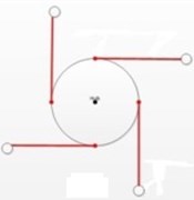
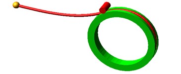
In Fig. 1, the basic configuration of space webs includes central rigid body, tether, space web, corner masses, which can deploy a web structure with certain area by using centrifugal force, and capture non-cooperative targets of different sizes within a certain distance.
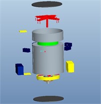
The designed double rotational space web system shown in Fig. 2, uses a satellite as the launch platform, a compression spring casting netting module to capture large non-cooperative targets. The Thin film solar panels, one of the latest rotational deployment technique, coupled with the rotational space web system are called double rotational space web system.
Fig. 1Spinning web configuration
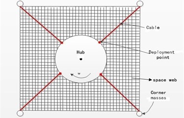
Fig. 2Spinning space web system
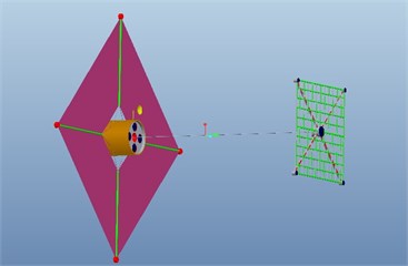
The satellite in this thesis applies multi-task and multi-module design and the main mission is using its own propulsion system to transfer netting module to the predetermined orbit and using target identification system to cast netting module. In Fig. 2, integrated layout about different subsystems is used. Thin-film solar panels are not only one of the latest technology, but also a large flexible rotational system, which make use of centrifugal force to deploy rotational membrane covered the main body, and this technology can greatly reduce the quality of entire system, and expand the solar panels larger [13].
Five cylindrical holes opened at the head of satellite are called the launcher for storing and casting the netting modules as shown in Fig. 3. Each launcher contains a netting module. Depending on the size of the target, this system can select the appropriate netting module to capture targets. At the bottom of the launcher the reel, drag tether, release springs, the electronic control module are attached. When the launch starts, release springs catapult netting module, and the reel, drag tether are used to control the release speed of netting module, the reaction wheel inside netting module is used to control the angular velocity of the centeral rigid body.
Fig. 3Launching canister
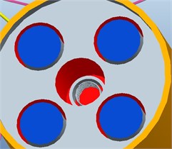
Fig. 4Netting module
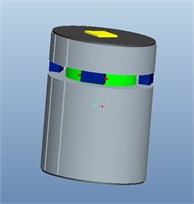
Netting module shown in Fig. 4, apply the cylindrical structure with the maximum diameter of 135 mm, total height 150 mm, which is divided into three layers: the upper, middle, lower chamber. The following structures is included: a cylindrical tube, masses, tether and space web, release device for masses, reaction wheels, lithium-ion batteries, flywheel motor, micro-processing systems, and other electronic devices. Release device for masses connected with the four masses locate on the lower surface position of the upper chamber. Reaction wheel is located on the upper surface position of the lower chamber, mainly for controlling the rotation speed of netting module.
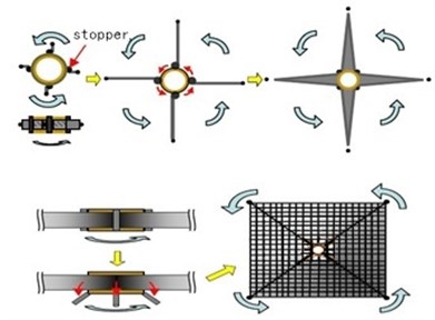
The main working schematic diagram of netting module is shown in Fig. 5, including a central rigid body, tether, space web, corner masses, stopper. When releasing the masses attached to forefront of tethers at the beginning of deployment, net module deploy the tethers and webs by the centrifugal force. During the deployment, space webs are firstly folded on the tethers and then unfolded after the tethers are extended entirely. At the start of the first stage, open the stoppers to rotate relatively to the center rigid body which can ensure tethers to extend fully. At the end of the first stage, release the stoppers, and net start deployment slowly.
Fig. 5Schematic diagram of netting module
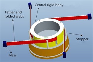
Fig. 6Net folding manner
3. The folding and deployment strategies of space webs
The folding and unfolding strategy about space webs is very crucial to successful deployment. Domestic and foreign scholars have carried out studies [14-16].
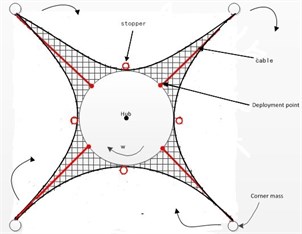
The main folding patterns of space webs include complete star folding, incomplete star folding, zig-zag folding, wrap-around folding of star arms. For this double rotational web system, firstly fold the web along four radial tethers whose edges are restricted by stoppers, then apply wrap-around folding pattern of star arms and coil tethers and webs in sequence around the central rigid body, shown in Fig. 6.
The unfolding strategy of space webs has two types: controlled one-step deployment and controlled two-step deployment. Studied results prove that these two strategies are both feasible. The simple and controllable two-step strategy is considered, and controlled one-step strategy is set as a backup strategy to ensure the normal deployment of space webs.
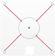
When the rotation speed of central body is raised up to the predetermined speed by using the reaction wheel, the corners masses are released, and the deployment start. The deployment process is shown in Fig. 7-8.
Fig. 7Deployment stages: a) initial state, b) deploying for first step, c) complete deployment for first step, d) full deployment for second step
a)
b)
c)
d)
First stage: the released masses driven by the centrifugal force deploy the tethers and folded webs, and the first stage will be completed after tethers are fully extended.
Second stage: open downwardly the stoppers, release the folding webs to automatically expand into a square configuration. When the webs are fully expanded, the second phase is completed.
Fig. 8Two-step deployment for space web
4. Kinematic modeling and simulation analysis of web deployment
4.1. The simplify of kinematic model
After the first step is completed, folded web deployment process will not be a big problem, if the stoppers are successfully released. So the first step of the deployment process is crucial to the success of web deployment, and then the kinematic model can be established by the simulation software ADAMS to simulate the first stage deployment of this system. Because of difficult folding web modeling, the kinematic model should be simplified.
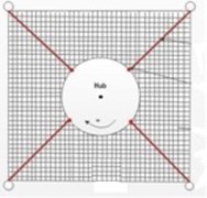
The main components of this system include central rigid body, tether, space web, corner masses, stopper. During the first stage, the webs are folded on the tether, which may be seen as increased length of the tether. So the folded webs and tethers can be simplified as flexible body, the same length as the tether length, the same mass as the total mass of folding webs and tethers; the central rigid body, corner masses, stoppers are regarded as rigid bodies, where one end of the flexible body is fixed to central body and the other end is fixed to rigid body of corner masses, and stoppers are fixed to the ground to make the flexible body expand in order. The simplified model is shown in Fig. 9.
Fig. 9Simplified kinematic model
4.2. The modeling of flexible body and rigid body
The model of central rigid body: firstly create a solid model in Pro/ENGINEER. Due to simulate central rigid in space environment, so three layer model is established, and the diameter of the middle layer is 200 mm. When the model is completed, it is saved as Parasolid format and stored at ADAMS working directory. Finally, import the file into ADAMS software, and define the material property of this rigid body.
The model of flexible body: ADAMS provides four methods to generate flexible body: stretching method, geometry method, the grid file imported to finite element model, macros generated by ANSYS software. For the simple shape of components, stretch mode can be directly used to generate the flexible member; for complex shape rigid member can be built at first and then the meshes are divided.
The idea of discretization is used in this paper with a number of very small cylindrical rigid units instead of the flexible body, and limited degrees of freedom of nodes representing infinite degrees of freedom of flexible bodies. The bushing force is used to connect small cylindrical rigid units, so elastic deformation of these element nodes can be approximated with the deformation of the flexible body. Creating steps of the flexible tether are as follows:
1) Create a small cylinder with the diameter of 4 mm, length of 10 mm, where its length is much smaller than the length of the tether;
2) Copy fifty such small cylinders by using a macro command;
3) Move these copied cylinders at the same distance and the same direction by a macro command;
4) The bushing forces are applied between these small cylindrical rigid units by another macro command.
In addition, the stoppers, and corner masses are directly using Cylinder and Sphere commands for modeling in ADAMS software to get two rigid bodies. By user-defined options of rigid bodies the simulated components can be acquired.
4.3. Contact definition and creation of joints and motion
Before defining the contact the flexible tether coiled around central rigid body must be established to simulate the initial state of space web system. In this coiling process the whole flexible body is firstly moved, and then the macro command is used to complete the coiling.
In the simulation, accelerations in three directions are set as zero due to weightlessness of space web deployment. In addition, the contacts between the central rigid body and the tether, the stopper and tether are needed to define.
The define of impact force in ADAMS has two ways: compensation method and impact function method. Since the compensation method is difficult to accurately set the parameters, impact function method is generally adopted to calculate the impact force, which is based on the impact function to calculate the elastic force and damping force between two components. Before the simulation of contacts, the stiffness, force exponent, damping, penetration depth are needed to determine in Table 1.
Table 1The simulation parameters
Stiffness | 2.0E+005 | Damping | 10.0 |
Force exponent | 1.1 | Penetration depth | 0.1 |
Fig. 10Whole kinematic model
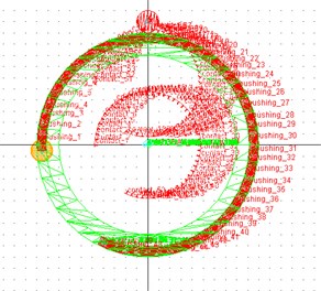
The joints and motions are added. A revolute is applied between central rigid body and the ground in the center; fixed joints are added between tether and corner mass, tether and central rigid body, stopper and ground, which can define the kinematic relationship of the released corner mass driving the flexible tether. Finally a rotational joint motion is created on the revolute by ADAMS rotary driven tool. After setting the simulation parameters the whole kinematic model is completed. Considering the complexity of the tether model, only one tether is established, and the final model is shown in Fig. 10.
4.4. The kinematic simulation analysis of space webs
The simulation parameters of rotational web system are as follows: the diameter of a small cylinder of tether 4 mm, length 10 mm, total length 500 mm, total mass 0.5 kg; masses are modeled as sphere. Parameters: center angular velocity 30 d/s, mass of masses 0.5 kg, mass of central rigid body 2 kg.
Fig. 11Deployment simulation curves of space web
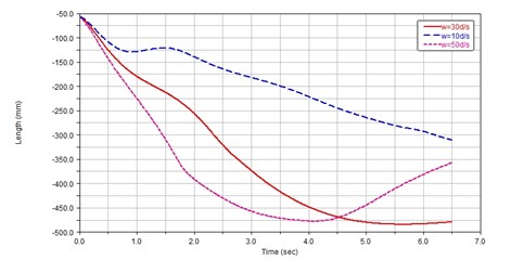
a) Web deployment curve with different central angular velocity
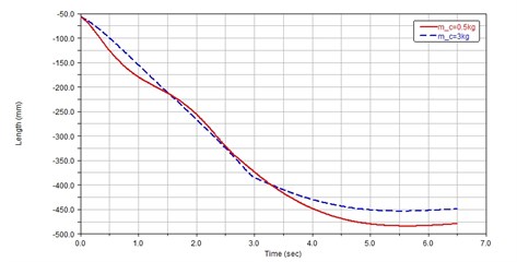
b) Web deployment curve with different mass of corner masses
c) Web deployment curve with different mass of central rigid body
The tether with many cylinders are used to simulate real tether and folding webs with equivalent quality; and a single tether is also applied as a simulation object to improve computational efficiency. So the simple kinematic model is established by the above method, where one end of the tether is fixed with central rigid body, and the other end fixed with corner masses. By releasing the corner masses, the tether is driven to elongate gradually through the stopper within the centrifugal force.
In order to study the different parameters on the influence of the space web deployment in the first phase, three kinematic parameters are set to analyze the movement. The first group: the central angular velocity 10 d/s, 30 d/s, 50 d/s, the other parameters remain unchanged; the second group: mass of corner masses 0.5 kg, 3 kg, the other parameters remain unchanged; the third group: mass of central rigid body2 kg, 8 kg, the other parameters remain unchanged. Three sets of parameters are expanded on the web simulation analysis, and the curves of results are shown in Fig. 11.
In Fig. 11(a), when the center speed is 10 d/s, the tether will be the same length during about 0.5 s, which has the impact on the deployment; the re-coiled phenomenon will be appeared with the speed 50 d/s after full deployment; the tether can smoothly stretch when the center speed is 30 d/s. Therefore, the center speed 30 d/s can be appropriate motion parameters.
In Fig. 11(b), it can be clearly seen that when the mass of corner masses is 3 kg, the tether expand more stably, but mass 0.5 kg of the masses is selected considering the quality limits of the system.
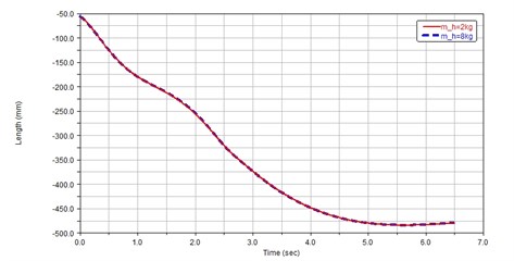
In Fig. 11(c), when the mass of the central rigid body is increased to 8 kg, tether expanding curves almost coincide, which the mass of central rigid has less impact on the deployment, and mass 2 kg of the central rigid is selected considering the quality limits of the system.
Set simulation acceleration zero to simulate space microgravity environment. The simulation results of space web deployment in first stage shown in Fig. 12 are required with the above suitable kinematic parameters and the simulation time is set to 6.5 s. From the results, flexible tether can be smoothly elongated within 6.5 s, and the confusion problems about tether and central rigid body have not appeared during the deployment.
Fig. 12The first stage of space web deployment
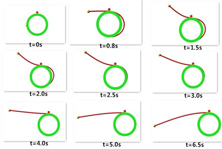
Fig. 13Bushing force curves of flexible tether between two cylinders
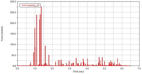
The bushing force curve of two cylinders of tether is shown in Fig. 13. The bushing force is constantly changing, but bushing force variation is relatively large over a period of time because of the contact between tether and central rigid or stoppers, which can simulate appropriately the force change of the tether by using bushing force.
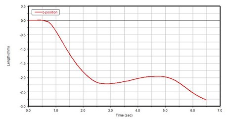
The out-of-plane displacement of the corner mass is shown in Fig. 14. It can be seen that in the simulation time of 6.5 s, the maximum displacement of the corner mass is 2.7 mm, thus the conclusion can be drawn that the space web deployment in the first phases is in almost two-dimensional plane, and the out-of-plane displacement in short time is negligible.
Fig. 14Corner masses displacement in Z direction
5. Conclusions
A new double rotational space web system is proposed in this paper from the advantages of rotational webs to analyze the deployment characteristics of the rotating web and simulate the first-stage deployment of space webs by using the simplified kinematic model. The different parameters about central rigid body and corner masses are studied to analyze the influence on the space web deployment.
From the simulation results, if the rotational speed of the central rigid body is too small, the tether does not stretch in a short time; if the speed is too high, the recoiled phenomenon of the tether will appear; large mass of corner masses has the advantages of the elongation of tether, but the system has the certain quality restriction; the web deployment is not significantly affected by the mass of central rigid body; the small out-of-plane displacement of corner masses can be negligible. Therefore, these suitable parameters of central rigid body and corner masses are set to obtain ideal kinematic model of rotational web deployment in ADAMS, which can provide some support for the second step deployment and eventually capture the scheduled large non-cooperative targets.
References
-
Gong Z. Z., Xu K. B., Mu Y. Q. The space debris environment and the active debris removal techniques. Spacecraft Environment Engineering, Vol. 31, Issue 2, 2014, p. 129-135.
-
Ma N., Gui X. Z. Foreign space debris removal plan. Space International, Issue 2, 2013, p. 64-69.
-
Jia J., Wang Y. Simulation of flexible net capture process for space debris. Spacecraft Environment Engineering, Vol. 31, Issue 2, 2014, p. 136-140.
-
Nakasuka S., Funane T., Nakamura Y. Sounding rocket flight experiment for demonstrating “Furoshiki Satellite” for large phased array antenna. Acta Astronautica, Vol. 59, Issue 1, 2006, p. 200-205.
-
Bischof B., Kerstein L., Starke J. ROGER- Robotic geostationary orbit restorer. 4th International Astronautical Congress, Bremen, Germany, 2003.
-
Hoyt R. P., Slostad J. T., Frank S. S. A modular momentum-exchange/electrodynamic-reboost tether system architecture. 39th Joint Propulsion Conference and Exhibit, Huntsville, Alabama, 2003.
-
Summerer L., Purcell O., Vasile M. Making the first steps towards solar power from space-microgravity experiments testing the deployment of large antennas. 60thInternational Astronautical Congress, Daejeon, Korea, 2009.
-
Lavagna M., Armellin R. Debris removal mechanism based on tethered nets. International Symposium on Artificial Intelligence, Robotics and Automation in Space, Torino, Italy, 2012.
-
Zhai G., Zhang J. R. Space tether net system for debris capture and removal. 4th International Conference on Intelligent Human-Machine Systems and Cybernetics, Nanchang, Jiangxi, 2012.
-
Chen Q., Yang L. P. Research on casting dynamics of orbital net systems. Journal of Astronautics, Vol. 30, Issue 5, 2009, p. 1829-1833.
-
Yu Y., Baoyin H. X., Li J. F. Dynamic modelling and analysis of space webs. Science China Physics, Mechanics and Astronomy, Vol. 54, Issue 4, 2011, p. 783-791.
-
Ma J., Huang P. F., Meng Z. J. Design and dynamic modeling of autonomous maneuvering tethered-net space robot system. Journal of Astronautics, Vol. 34, Issue 10, 2013, p. 1316-1322.
-
Tsuda Y., Mori O., Funase R. Achievement of IKAROS – Japanese deep space solar sail demonstration mission. Acta Astronautica, Vol. 82, Issue 2, 2013, p. 183-188.
-
Tibert G., Gardsback M. Space webs final report. ESA, Advanced Concepts Team, Rept, 2006.
-
McKenzie D., Cartmell M., Radice G. Space webs: final report. ESA, Advanced Concepts Team, Rept, 2006.
-
Gardsback M. Deployment control of spinning space webs and membranes. Mekanik, Kungliga Tekniska högskolan, 2008.
About this article

This work was supported by National Natural Science Foundation of China (Grant No. 51105196), Natural Science Foundation of Jiangsu Province (Grant No. BK2011733), Science and Technology Innovation Fund of Shanghai Aerospace (Grant No. SAST201320), and Shanghai Key Laboratory of Deep Space Exploration Technology.
