Abstract
The paper is devoted to the problem of stress measurements in polymeric films with Braille and tactile relief elements by using the method of photo-elasticity. A separate Braille and tactile relief element is analyzed numerically by using an axisymmetric model and the problem of determination of distribution of equivalent stress is investigated. Nodal stresses are calculated by using the procedure of conjugate approximation. Equivalent stresses are represented by intensity of the image. A special experimental setup was developed for the measurement of stresses in polymeric materials. The obtained results of investigations are used in the process of design of polymeric films with Braille and tactile relief elements by taking into account the stress distributions in them.
1. Introduction
An important problem of the integration of disabled people (among them blind and visually impaired people) into the society exists in aging societies. Thus it becomes desirable to use the Braille and tactile relief elements on various products or their packages produced from polymeric and other materials [1-3].
Various stress distributions take place in transparent and usually optically isotropic polymeric materials. The character of distribution of stresses in these materials enables to measure the qualitative and quantitative parameters of Braille and tactile relief elements. Special requirements are to be satisfied in order to ensure sufficient quality of Braille and tactile relief elements during the process of use of a package or a label [4-6].
The main objective of this paper is to perform experimental stress analysis of the Polyethylene Terephthalate (PET) and Polypropylene (PP) polymers and their applicability for Braille and tactile relief elements. Also, this paper extends the investigations to new types of Braille and tactile relief elements. Braille and tactile relief elements are analyzed numerically by using an axisymmetric model and the distribution of equivalent stresses is investigated. Nodal stresses are calculated by using the procedure of conjugate approximation; equivalent stresses are represented by the grayscale level of the digital image. The numerical procedure is based on finite element analysis [7-9], the technique of conjugate approximation [7, 8] and representation of equivalent stresses [10].
A special experimental setup was developed for the measurement of distribution of stresses in samples of polymeric materials with Braille and tactile relief elements. Physical parameters of PET and PP samples are presented in Table 1 (these materials are used for packaging of food and non food type products) [3].
As mentioned previously, the main objective of this paper is to measure and investigate the character of distribution of stresses in polymeric packages with Braille and tactile relief elements and also in a special Braille and tactile relief element of axisymmetric type.
Table 1Physical parameters of investigated samples [3]
Parameter | Samples | |
Plastic PET | Plastic PP | |
Modulus of elasticity, (MPa) | 1.41×10⁴ | 1032-1720 |
Poissons ratio, | 0.44 | 0.45 |
Strength in tension, (MPa) | 172 | 29.3-38.6 |
Breaking elongation, (%) | 12-55 | 100-600 |
Impact strength, (MPa) | 13-35 | 2.8-6.9 |
Thickness of the material, (mm) | 0.25 | 1.0 |
Density of the material, (g/cm3) | 1.335 | 0.85-0.854 |
2. Investigation of stress distributions in axisymmetric Braille elements
2.1. The description of the numerical procedure
Nodal values of the stresses are determined from:
where stands for the radial coordinate; denotes the axial coordinate; denotes the coordinate in the angular direction;, , , are the vectors of nodal values of the stresses , , , and:
where is the row of the shape functions , ,…, of the two dimensional Lagrange quadratic finite element.
Stresses in the expression of are determined from:
where is the vector of nodal displacements, is the matrix of elastic constants and:
2.2. Braille element of type I: the stress field for a quarter of a disk
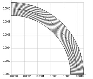
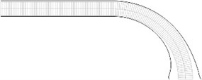
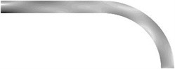
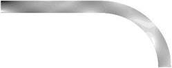
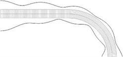
The structure consists of one row of elements located on one fourth of a disk with radius of the middle line 0.001 m and semi thickness 0.0001 m. The following parameters are assumed: modulus of elasticity 10.32×10⁸ Pa, Poisson’s ratio 0.45, density of the material 850 kg/m3. The left end of the structure coincides with the axis of symmetry. 64 two dimensional Lagrange quadratic finite elements are used; the finite element mesh is illustrated in Fig. 1.
Fig. 1Finite element mesh of the structure
2.2.1. The static problem
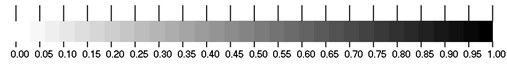
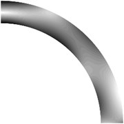
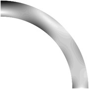
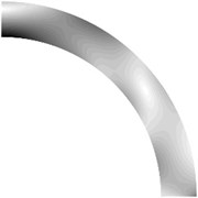
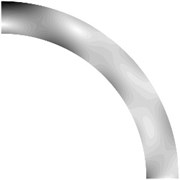
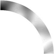
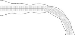
Displacements in the direction of the axis of the three nodes on the left end of the structure and displacements in the direction of the axis of the three nodes on the right end of the structure are assumed equal to zero. Non-dimensional displacements in the direction of the axis of the three nodes on the right end of the structure are assumed equal to one (the structure has 765 degrees of freedom after taking the boundary conditions into account). Equivalent stresses are represented by grayscale levels in Fig. 2 (black color of the images corresponds to highest values of equivalent stress; white color corresponds to lowest values of equivalent stress); the grayscale bar is presented in Fig. 3.
Fig. 2Equivalent stresses
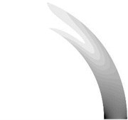
Fig. 3The greyscale bar
2.2.2. Visualization of the eigenmodes
Displacements in the direction of the axis of the three nodes on the left end and all displacements of the three nodes on the right end of the structure are assumed equal to zero. Equivalent stresses for the first ten eigenmodes are presented in Fig. 4.
It is clear that the complexity of stress distribution in general increases with the increase of the number of the eigenmode and that maximum values of equivalent stress are usually located at the surface of the structure. But experimental investigations of polymeric materials with Braille elements of this type indicate that polymeric Braille materials of this type experience degradation of strength at their top parts due to frequent contacts with fingers. Thus Braille elements having a flat top part are to be preferred what leads to the investigation of Braille elements of the second type.
Fig. 4Equivalent stresses for a) the first, b) the second,…, j) the tenth eigenmodes
a)
b)
c)
d)
e)
f)
g)
h)
i)
j)
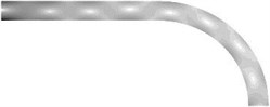
2.3. Braille element of type II: the stress field for the structure with improved tactile relief element
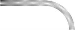
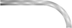
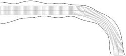
The structure consists of one row of elements located on a straight part with the length equal to the length of the middle line of one fourth of a circle with another part comprising a quarter of the disk. The radius of the middle line of the part of the circle is 0.001 m and semi thickness of the structure is 0.0001 m. The following parameters are assumed: modulus of elasticity 10.32×10⁸ Pa, Poisson’s ratio 0.45, density of the material 850 kg/m3. The left end of the structure coincides with the axis of symmetry; 64 2D Lagrange quadratic finite elements are used: 32 for the straight part and 32 for the circular part.
2.3.1. The static problem
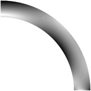
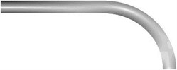
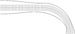
Displacements in the direction of the x axis of the three nodes on the left end of the structure and displacements in the direction of the y axis of the three nodes on the right end of the structure are assumed equal to zero. Non-displacements in the direction of the axis of the three nodes on the right end of the structure are assumed equal to one (after taking the boundary conditions into account the structure comprisess 765 degrees of freedom) Equivalent stresses are presented in Fig. 5.
Fig. 5Equivalent stresses
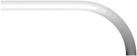
Fig. 6Equivalent stresses on the lower and upper surfaces
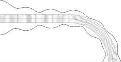
As noted previously, Braille elements with a flat top part have an advantage over the Braille elements of the first type. Thus they are recommended for practical applications and deserve more detailed analysis. Maximum equivalent stress usually takes place at the surfaces of the Braille and tactile relief element. In order to be able to interpret the values of equivalent stress on the lower and upper surfaces of the Braille element a graphical representation is desirable. Equivalent stresses on the lower and upper surfaces represented in the normal direction to the surfaces are presented in Fig. 6.
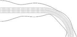
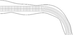
Displacements in the direction of the axis of the three nodes on the left end of the structure and all displacements of the three nodes on the right end of the structure are assumed equal to zero (after taking the boundary conditions into account the structure has 765 degrees of freedom) Equivalent stresses for the first ten eigenmodes are presented in Fig. 7. Equivalent stresses on the lower and upper surfaces represented in the normal direction to the surfaces are presented in Fig. 8.
Fig. 7Equivalent stresses for a) the first, b) the second, …, j) the tenth eigenmodes
a)
b)
c)
d)
e)
f)
g)
h)
i)
j)
3. Experimental measurements of stresses in a sheet of polymeric film with Braille elements
3.1. The experimental setup
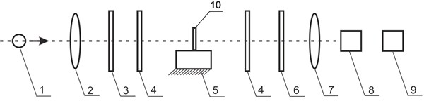
A special experimental setup was produced for the investigation of distributions of stresses in polymeric packages with Braille and tactile relief elements. It comprises General Purpose Strain Viewer produced by the company Sharpless, digital camera EO-1312c and a personal computer (Fig. 9).
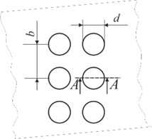
Geometrical parameters of Braille and tactile relief elements are presented in Fig. 10. Two different samples of transparent polymeric materials were investigated: PET samples with formed surface elements (sample 1 and sample 2) and PP samples with elements of Braille writings (sample 3). Measurement of distribution of stresses in the investigated samples are performed in static conditions.
Transparent optically isotropic polymeric material becomes optically anisotropic during the process of production due to residual stresses. Thus it divides the propagating light into two polarized waves which occur due to different velocities of the propagation of waves in the polymeric material in different directions. This reason causes a time delay when mutually perpendicular polarized waves reach the observer. The image produced by the polariscope represents this time delay – in the regions of polymeric material with stresses result in white areas, while the unstressed regions result into dark areas.
Fig. 8Equivalent stresses on the lower and upper surfaces for a) the first, b) the second, …, j) the tenth eigenmodes
a)
b)
c)
d)
e)
f)
g)
h)
i)
j)
Fig. 9Layout of the setup for investigation of stresses: a) structural diagram; b) external view of the designed experimental setup: 1 – stands for the light source, 2 – collimating lens, 3 – polarizer, 4 – quarter wave plate, 5 – background on which a sample is located, 6 – analyzer, 7 – field lens, 8 – digital camera EO-1312c, 9 – personal computer, 10 – investigated sample
a)

b)
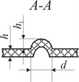
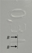
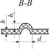
Fig. 10Representation of geometric parameters of Braille and tactile relief elements: a) top view of the Braille element: d – diameter of the Braille dot, b – distance between Braille dots; b) side view of Braille on polymeric material (A-A): h – thickness of polymeric material, h1 – height of the Braille dot; c) the surface of the graphical image; d) profiles of surface elements (B-B): h – thickness of the polymeric material, h1 – height of the graphical element, d – width of the graphical element
a)
b)
c)
d)
3.2. Results of experimental investigations
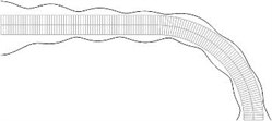
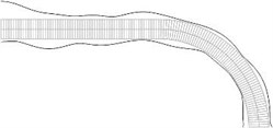
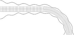
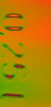
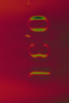
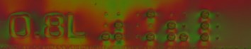
The images of samples obtained by using the method of photo-elasticity are presented in Table 2. The resulting interference color (see Table 3) enables optical determination of the time delay caused by the light wave propagation through the investigated sample.
Note that the color structure in samples 1, 2, 3 is similar; color regions of the fourth order dominate and the values of stresses are highest there. Stresses in the regions of Braille and tactile relief elements stresses can be clearly seen.
Table 2Photo-elastic images for the samples
Sample 1 | Sample 2 | Sample 3 |
 |  |  |
4. Conclusions
Separate Braille and tactile relief elements are investigated using computational techniques in an axisymmetric model geometry. Nodal stresses are calculated by using the procedure of conjugate approximation. Equivalent stresses are represented according to the intensity of the image. Two types of Braille and tactile relief elements were investigated: a quarter of a disk and a structure with the special type of tactile relief elements.
Results of experimental investigations indicate that Braille elements of the first type experience wear and degradation of strength of material at the top due to frequent contacts with fingers and other sheets of polymeric material. Thus Braille and tactile relief elements with a flat top could be considered as an alternative. Braille and tactile relief elements of the second type have a flat top and thus are advantageous from the point of view of wear and degradation of strength of the polymeric material.
Table 3Color index representing the source of white light [11]
Color | Nanometers (10-9 m) | Color | Nanometers (10-9 m) |
First order colors | Second order colors | ||
Black | 0 | Green – yellow | 830 |
Grey | 140 | Orange | 960 |
White | 260 | Rose Red | 1050 |
Pale yellow | 330 | Purple | 1150 |
Orange | 460 | Green | 1350 |
Dull red | 520 | Third order colors | |
Purple | 580 | Green – yellow | 1450 |
Deep blue | 620 | Pink | 1550 |
Blue – green | 700 | Green | 1800 |
Fourth order colors | |||
Pink | 2100 | ||
Green | 2400 | ||
The darkest parts of the images correspond to highest values of equivalent stress. At those places the wear of material is highest. In general, higher eigenmodes correspond to more complicated distributions of equivalent stress and the highest equivalent stress is located at the surfaces of the tactile relief elements.
Braille elements of the second type have advantages in practical applications and are investigated in more details – graphical representations of the equivalent stress on the lower and upper surfaces are obtained. Such graphical representations help to determine places with the highest values of the equivalent stress.
An experimental setup based on photo-elastic method for the measurements of stresses in sheets of polymeric material with Braille and tactile relief elements is developed. The fourth order color structure is employed for the measurement of stresses in Braille elements. The obtained results are used for improvement of design of sheets of polymeric material, as well as packages, labels and pictures with Braille and tactile relief elements.
I. Venytė performed experimental measurements of stresses in a sheet of polymeric film with Braille elements. She also took part in the development of the numerical model of Braille and also in the development of the experimental setup. E. Kibirkštis proposed and developed the experimental setup, performed the interpretation of experimental results and took part in the development of the numerical model. A. Voloshin enhanced the developed experimental setup used for investigations, investigated the correspondence between experimental and numerical results and took part in the interpretation of experimental results. K. Ragulskis proposed the geometries of Braille and tactile relief elements which were used in numerical calculations and performed the interpretation of the obtained numerical results. L. Ragulskis was responsible for the numerical implementation of the model.
References
-
Chen X., Barnes C. J., Childs T. H. C., Henson B., Shao F. Materials’ tactile testing and characterisation for consumer products’ affective packaging design. Materials and Design, Vol. 30, Issue 10, 2009, p. 4299-4310.
-
Kim M. S., Young Kim I., Kyu Park Y., Ze Lee Y. The friction measurement between finger skin and material surfaces. Wear, Vol. 301, 2013, p. 338-342.
-
Beswick R., Dunn D. Plastics in Packaging. Western Europe and North America, Rapra Technology Limited, 2002, p. 141.
-
LST EN 15823:2010 Packaging – Braille on Packaging for Medicinal Products.
-
Seideii P. Axisymmetrical buckling of circular cones under axial compression. Journal of Applied Mechanics, Vol. 23, Issue 4, 1956, p. 227-232.
-
Maksymuk O. Calculation of stresses in the half plane of stamps under the action of various forms. Mathematical Methods and Physical Mechanical Fields, Vol. 43, Issue 2, 2000, p. 155-162, (in Russian).
-
Segerlind L. J. Applied Finite Element Analysis. Moscow, Mir, 1979, (in Russian).
-
Gallagher R. H. Finite Element Analysis Fundamentals. Moscow, Mir, 1984, (in Russian).
-
Bathe K. J. Finite Element Procedures in Engineering Analysis. Prentice-Hall, New Jersey, 1982.
-
Samul V. I. Basis of the Theory of Elasticity and Plasticity. Moscow, Vysshaja Shkola, 1982, (in Russian).
-
Sharples Stress Engineers Ltd. Manual for General Purpose Strain Viewer, www.sharplesstress.com.
About this article

Authors thank the anonymous reviewers for their valuable comments which did help to improve the paper substantially.
