Abstract
This study has presented a method to estimate the damage location in the concrete gravity dam monolith. The first four vibration mode of the highest monolith of the Koyna dam was estimated and analyzed by the combined discrete and continuous wavelet transform. The position of the damage scenarios was identified by using bior 3.9 wavelet in the spatial variation of the data response. The sensitivity of wavelet to random signal noise was investigated by using noise to displacement response of cracked monolith. Three noise levels were introduced in the model and the capacity of this method to detect damage from noisy data was discussed.
1. Introduction
Concrete dams play important role in different disciplines such as irrigation, hydropower generation and flood controlling. Due to its simplicity and functionality in designing and constructing, Gravity dam is known as one kind of concrete dams having commonly been constructed and used around the world. It is notable that these dams encompass 30 % of all constructed dams in the world. These structures maintain their stability from the geometric shape, mass and strength of the concrete. Crack occurrence and propagation on dams can result in devastating economic and vital consequences. accordingly, it is necessary to develop the suitable damage detection system to estimate any crack in the early forming stages and secure the lifetime of the dam.
The existence of cracks in gravity dam may influence the dynamic behavior of structures (i.e., natural frequencies and modal vibration), which in turn can cause catastrophic dam failure. Therefore, the appropriate analysis must be done to estimate the dynamic response of the dam. In light of this concept, the modal analysis as a well-known procedure for dynamic structure analysis can evaluate the seismic response of structures in the range of elastic behavior. This approach is frequently utilized in all hydraulic structures in which their behavior always is in elastic range due to the exerted forces of the earth’s movement. The response of the structures is obtained by combining vibration modes needed to be calculated only in initial modes; because, the structure response against the earthquake loads is negligible on the higher modes [1].
In the field of signal processing and identification damage methods used includes improved LMD, EMD [2, 3], Inverse Optimization [4] and Wavelet Transform (WT). Over the decades, WT is extensively used in different fields of civil engineering study [5, 6]. WT has become one of the applied approaches in detecting structure damages as well. By this technique, the wavelet coefficients are calculated in displacement of structure based on static forces or dynamic mode shapes. The distribution of wavelet coefficients of the damaged structure is investigated, at which the points of structure showing the abrupt change of wavelet coefficients are considered as damaged area [7]. There have been several studies to identify the existence and location of structural damage by using WT, some of them are included here. Hwang et al. [8] used the hybrid WT and Artificial Neural Network (ANN) to identify the damage in gas pipelines. Douka et al. [9] was estimated both the location and size of the crack in a cracked cantilever beam using continuous wavelet transform to fundamental vibration mode. Ovanesova and Suárez [10] presented use of WT to detect cracks in frame structures, such as beams and plane frames. The continuous wavelet transform is broadly used to detect structural damages reported in different researches [11-14]. Rucka [15] was investigated the effectiveness of higher vibration modes in steel beam to the wavelet-based damage detection technique. The results indicated that higher modes are more sensitive to the damage. Liu et al. [16] considered WT as a signal processing technique in monitoring the health of structures. They used wind turbines as a case study. Khorram et al. [17] employed WT to identify the damage of the concrete beams from the moving load. Vafaei and Adnan [18] explored the vibration damage of the airport control tower by using WT analysis. Ravanfar et al. [19] used two-step wavelet transform to identify the location and intensity of the damage in the concrete beam from the flexural vibrations. Chen et al. [20] was studied of detection on damage occurrence of the five-story shear building. The researchers were applied CWT to the structural acceleration responses. The observations indicate that proposed detection method can accurately identify the damage time present and damage location due to a sudden stiffness reduction in terms of the event time and spatial distribution of coefficient spikes of the CWT.
This study has aimed to evaluate the capacity of the application of CWT, DWT and their combination method to detect the damaged areas over the vibration response and the effect of the mode order on detecting damage of the dam monolith. Also, considering the possible damage scenarios, the effect of crack at various distances of downstream and upstream of the monolith have been examined and have been determined the position of critical damages on the basis of usages of CWT. Furthermore, the determination of the optimal analysis level DWT decomposition to extract the features of signal and properly detect structural damage has been studied. The effect of noise on the detection of crack has been investigated, eventually.
2. Wavelet transform theory
Wavelet transform is one of the most versatile mathematical transformations in signal processing domain. Generally, mathematical transportation to a signal has been used to extract the features that are not available in the first signal. Wavelets are made of basic functions being able to describe signal in time (or place) and given frequency (or scale). The general algorithms of wavelet functions include continuous and discrete wavelet.
2.1. Continuous wavelet transformation
The continuous wavelet transform is usually defined as follows [21]:
where the wavelet coefficients are the result of the CWT of the signal , variable is the time or place, and which is a basic wavelet function and is called the mother wavelet is defined as:
The scale or dilation parameter, a, scales a function by compressing or stretching, while b is the translation of the wavelet function along the time or space axis and * corresponds to complex conjugate. According to Eq. (1), which is expressed as inner product, it can be considered that wavelet transform is, in fact, the measurement of similarity between the signal and basic functions. In other words, wavelet transform indicates how the signal is close to the wavelet in corresponding scale. In this case, a set of wavelet coefficients are obtained and the local information of the signal is extracted by estimating the coefficients. In this study, the large amount of wavelet coefficient that can be seen as sudden changes or peaks in the graph indicates the presence of damage in the studied position.
The effect of wavelet transform on detecting damage depends on selecting the appropriate wavelet function and the number of Vanishing Moments (VMs). The researchers have shown that the wavelet with two VMs would be more appropriate to identify the damage [9, 22]. Therefore, the wavelet of bior 3.9 with three VMs has been used in this paper.
2.2. Discrete wavelet transform
Contrary to the CWT, Discrete Wavelet Transform (DWT) calculates the wavelet coefficients at discrete intervals of time and scale. When the scaling factor and shifting factor of the basic wavelet function () are limited to discrete values, the analysis is done efficiently and accuratly. DWT has been used as a computational technique to extract information about non-stationary signals [23].
It can be expressed by:
where can be written as:
The input signal can be reconstructed by using the following equation:
In Eq. (5), as wavelet coefficients are divided into an approximation (low frequency) coefficient () at level () through a low-pass filter , and detail (high frequency) coefficients (, , ,…, ) at different levels (1, 2, 3,…) through a high-pass filter . () provides general information on the original signal, while (, , ,…, ) contains the detail information on the original signal such as period, break and jump. Then the original signal can be expressed as:
or simplified as follows:
As shown in Fig. 1, is the approximation of the original signal at level (), and is the detail of the original signal at different levels (1, 2, 3,…, ).
3. Numerical simulation
3.1. Proposed finite element model with damage scenarios
Gravity dams are built as separate monoliths that can separately maintain its stability. Due to the resistance against the cataclysmic earthquake damage on 11 December 1967, Koyna gravity dam has greatly been attended by the researchers working on structural damage analysis [24-26]. The earthquake made diagonal and horizontal cracks on the upstream and downstream faces in which the slope of the downstream face changes at the highest non-overflow monoliths of the dam. Thus, in this research, two-dimensional finite element of the highest non-overflow monoliths of the dam was modeled. Finite element was modeled by using 63952 of 4-node quadrilateral elements of plane stress with reduced integration which is denoted as CPS4R in ABAQUS finite element modeling software. Also in the current study, the interaction between water and dam in the reservoir and between dam and foundation have been ignored. To identify damage, the cracks as small as 0.02 meter length were hypothetically introduced in three different positions of the model. The finite element model of the monolith dam and the damaged scenarios are shown in Fig. 2. The material properties considered for concrete dam are as follows: the elasticity modulus 31027 MPa, the Poisson’s ratio 0.2 and the mass density 2643 kg/ m3.
The modal analysis has resulted in the first four modes of the model in both undamaged and damaged states. To validate, Fig. 3 has shown the first four natural frequency of finite element model of the dam and reference [27] article to a healthy state. There is a significant correspondence between the results from the study and results reported in the reference.
Fig. 1Three levels of discrete wavelet transformation
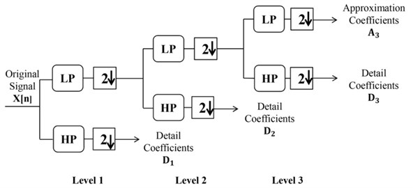
Fig. 2a) Finite element model, b) damage scenarios
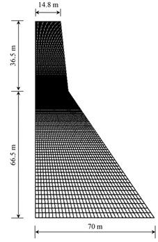
a)
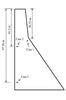
b)
3.2. Identification of damage position
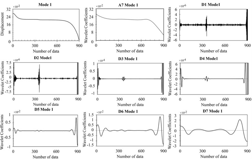
The wavelet analysis is conducted on monolith mode shapes assumed as a spatially distributed signal by using the BiorSplines wavelet family. Fig. 4 shows the response data, approximation and details in seven levels of analysis for damage case 1. It should be noted that higher levels of analyzing discontinuities from cracks cannot be considered separately, due to the analysis of approximation at any level of decomposition. With increasing the level decomposition, the approximation closes to 0. In this case, almost all features of the original signal are extracted. According to this figure, it can be seen that the details more accurately identifies the position of the cracks in the third level of analysis.
Fig. 3Comparison natural frequency between finite element model and ref. [27]
![Comparison natural frequency between finite element model and ref. [27]](https://static-01.extrica.com/articles/17269/17269-img4.jpg)
Fig. 4The response data, approximation and details in seven levels of DWT for damage case 1
According to Fig. 5, at the third level of DWT, details was analyzed by using CWT to have more precise details of wavelet coefficients.
The conversion of scale from 1-60 was used to extract the signal features. It is observed that the wavelet coefficients value is increased by increasing order mode. This indicates the sensitivity of the wavelet to the damage position in far higher mode shape. On the other hand, if the CWT of numerical mode shape is implemented for scales of 1-15, it is obvious in Fig. 6 that the absolute value of the maximum wavelet is regularly increased by increasing scale. Therefore, the crack position can be easily identified at scale = 15.
Also, no significant coefficient is observed in other situations away from the position of crack; because, a series of information from theoretical calculations is analyzed and doesnot include any noise and measurement errors. In actual tests, the expected noise destroys the obtained data. In this case, the wavelet coefficients behave in a totally different way, which will discuss in the next section.
Fig. 5Damage detection in four first modes of third level of DWT for damage case 1
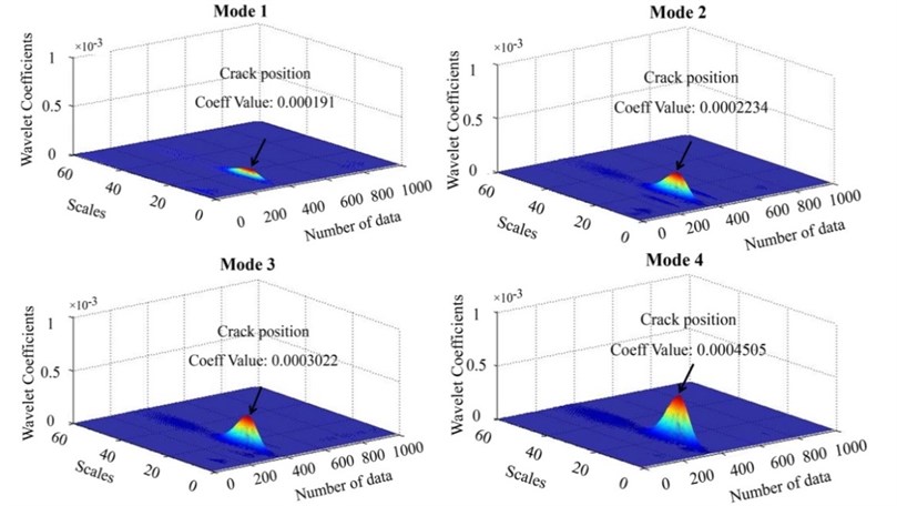
Fig. 6The wavelet transform showing the trend of the maximum coefficients at crack position of case 1
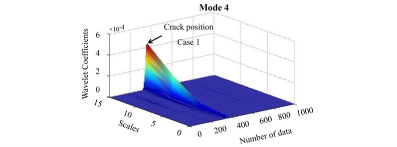
Fig. 7Damage detection in the combination of damage case 1 and damage case 2 of mode 2
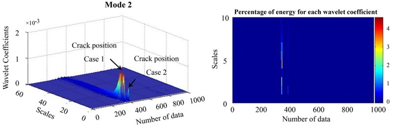
To examine the effect of crack position in the process of identifying the damage, the combination of different damage scenarios was evaluated. It is expected that the effect of observed damage would be significant in area of slope change in the downstream side. It is seen that the crack of case 2, located near the dip in upstream face, cannot be clearly distinguished from the case 1. Due to the slope of the crack in the case 1, the damage in case 1 has encompassed more damage area which in turn influence the identification of crack in case 2 (Fig. 7).
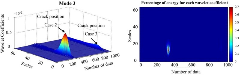
As it can be seen in Fig. 8, wavelet coefficients are higher in the proximity of the upstream face slope in combination of case 2 and case 3; as a result, wavelet is not sensitive to the crack being close to the support in the studied model.
Fig. 8Damage detection in the combination of damage case 2 and damage case 3 of mode 3
4. The effect of noise on damage detection
In a real experiment, it is impossible to avoid the measurement errors. To observe the effect of noise or measurement errors on the process of damage identification, a noise was added to the fourth mode of damage scenario in case 1 according to the following equation [28]:
Fig. 9The response noisy data and details in five levels of DWT for damage case 1
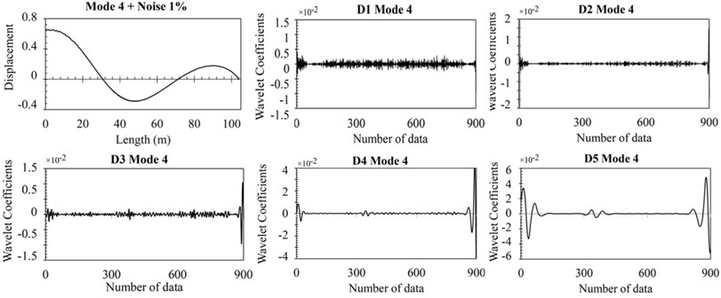
In Eq. (8), and are amounts of noise and the disturbances of modal shape, respectively. In this paper, three different levels of noise including 1 %, 3 % and 5 % were used. The noisy data has been analyzed under wavelet transform on the basis of the method presented in the previous section. Fig. 9 shows the signal discretization at different levels after adding intended noise. It can be observed that by applying 1 % noise and analyzing signals through five levels, the damage area well be detected, while Fig. 10 has shown that the position of crack is poorly determined by adding 3 % and 5 % noise, and consequently applying DWT to the same level. Therefore, it is necessary to decompose the signals at higher levels.
Fig. 10The response noisy data and details of DWT for damage case 1
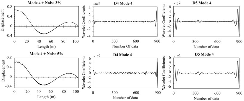
Fig. 11Damage detection in the three value of noise
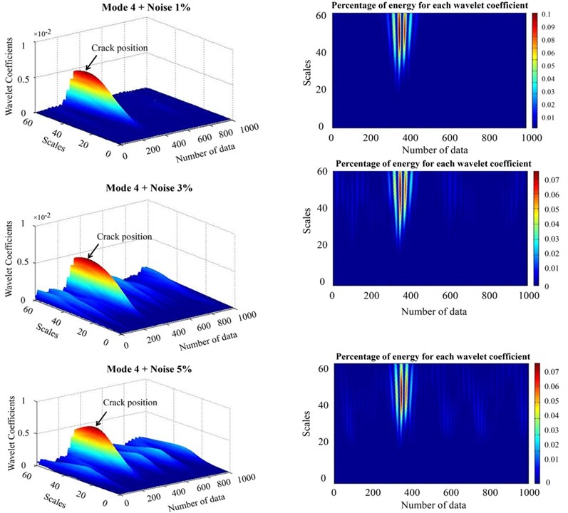
Also, after the application of CWT to the fifth level in the noisy data in Fig. 11, it is observed that in 1 % noisy data, the effect of measurement errors was eliminated and damage position can be recognized with high accuracy. While in the 3 % and 5 % levels of noise, it can be seen wavelet has significant value in other areas except the location of crack in spite of the high value of wavelet coefficient in the crack position. It was observed that by reducing scale, the value of wavelet coefficients in the other different areas is more than its value in the damaged area. Accordingly, it was impossible to detect damage location.
5. Conclusions
In this study, identifying the damage location in concrete gravity dams has been investigated by wavelet transform. For this purpose, various scenarios of damage were defined in the model, and the modal shape of the first four modes of the monolith of Koyna dam has been extracted. Then, the process of damage detection was accomplished by combination of discrete and continuous wavelet transform. Crack position was identified as abrupt changes in the wavelet coefficients in the damaged area. It was observed that the damage can accurately be detected in the high order mode.
To investigate the effect of cracks on each other in different situations, a combination of different damage scenarios was considered. As expected, the wavelet coefficients, in the elevation at which the slope of the downstream face changes abruptly, is higher than in other vulnerable situations. It was also observed that the wavelet is not sensitive to the closeness of damage to the support. Since preventing measurement errors in real experiments is unavoidable, noise data with different percentages was added and it was observed that the signal is required to be analyzed at higher levels by DWT so that damage can be identified.
References
-
Response Spectra and Seismic Analysis for Concrete Hydraulic Structures. U.S.A. c. o. Engineers, EM 1110-2-6050, 1999.
-
Li Y., Xu M., Wang R., Huang W. A fault diagnosis scheme for rolling bearing based on local mean decomposition and improved multiscale fuzzy entropy. Journal of Sound and Vibration, Vol. 360, 2016, p. 277-299.
-
Li Y., Xu M., Wei Y., Huang W. An improvement EMD method based on the optimized rational Hermite interpolation approach and its application to gear fault diagnosis. Measurement, Vol. 63, 2015, p. 330-345.
-
Kaveh A., Hoseini Vaez S. R., Hosseini P., Fallah N. Detection of damage in truss structures using Simplified Dolphin Echolocation algorithm based on modal data. Smart Structures and Systems, Vol. 18, 2016, p. 983-1004.
-
Abbaszadeh P. Improving hydrological process modeling using optimized threshold-based wavelet de-noising technique. Water Resources Management, Vol. 30, Issue 5, 2016, p. 1701-1721.
-
Nourani V., Tahershamsi A., Abbaszadeh P., Shahrabi J., Hadavandi E. A new hybrid algorithm for rainfall–runoff process modeling based on the wavelet transform and genetic fuzzy system. Journal of Hydroinformatics, Vol. 16, Issue 5, 2014, p. 1004-1024.
-
Wang J., Qiao P. On irregularity-based damage detection method for cracked beams. International Journal of Solids and Structures, Vol. 45, Issue 2, 2008, p. 688-704.
-
Hwang K., Mandayam S., Udpa S. S., Udpa L., Lord W., Atzal M. Characterization of gas pipeline inspection signals using wavelet basis function neural networks. NDT&E International, Vol. 33, Issue 8, 2000, p. 531-545.
-
Douka E., Loutridis S., Trochidis A. Crack identification in beams using wavelet analysis. International Journal of Solids and Structures, Vol. 40, Issue 13, 2003, p. 3557-3569.
-
Ovanesova A., Suarez L. Applications of wavelet transforms to damage detection in frame structures. Engineering Structures, Vol. 26, Issue 1, 2004, p. 39-49.
-
Chang C.-C., Chen L.-W. Vibration damage detection of a Timoshenko beam by spatial wavelet based approach. Applied Acoustics, Vol. 64, Issue 12, 2003, p. 1217-1240.
-
Gökdağ H., Kopmaz O. A new damage detection approach for beam-type structures based on the combination of continuous and discrete wavelet transforms. Journal of Sound and Vibration, Vol. 324, Issue 3, 2009, p. 1158-1180.
-
Rucka M., Wilde K. Application of continuous wavelet transform in vibration based damage detection method for beams and plates. Journal of Sound and Vibration, Vol. 297, Issue 3, 2006, p. 536-550.
-
Zhong S., Oyadiji S. O. Detection of cracks in simply-supported beams by continuous wavelet transform of reconstructed modal data. Computers and Structures, Vol. 89, Issue 1, 2011, p. 127-148.
-
Rucka M. Damage detection in beams using wavelet transform on higher vibration modes. Journal of Theoretical and Applied Mechanics, Vol. 49, Issue 2, 2011, p. 399-417.
-
Liu X., Leimbach K. R., Hartmann D., Höffer R. Signal analysis using wavelets for structural damage detection applied to wind energy converters. The 14th International Conference on Computing in Civil and Building Engineering, 2012.
-
Khorram A., Rezaeian M., Bakhtiari-Nejad F. Multiple cracks detection in a beam subjected to a moving load using wavelet analysis combined with factorial design. European Journal of Mechanics – A/Solids, Vol. 40, 2013, p. 97-113.
-
Vafaei M., Adnan A. B. Seismic damage detection of tall airport traffic control towers using wavelet analysis. Structure and Infrastructure Engineering, Vol. 10, Issue 1, 2014, p. 106-127.
-
Ravanfar S. A., Abdul Razak H., Ismail Z., Monajemi H. An improved method of parameter identification and damage detection in beam structures under flexural vibration using wavelet multi-resolution analysis. Sensors (Basel, Switzerland), Vol. 15, Issue 9, 2015, p. 22750-22775.
-
Chen B., Kang Y.-P., Li P.-Y., Xie W.-P. Detection on structural sudden damage using continuous wavelet transform and Lipschitz exponent. Shock and Vibration, Vol. 2015, 2015.
-
Kişi Ö. Stream flow forecasting using neuro-wavelet technique. Hydrological Processes, Vol. 22, Issue 20, 2008, p. 4142-4152.
-
Hong J.-C., Kim Y., Lee H., Lee Y. Damage detection using the Lipschitz exponent estimated by the wavelet transform: applications to vibration modes of a beam. International Journal of Solids and Structures, Vol. 39, Issue 7, 2002, p. 1803-1816.
-
Daubechies I. The wavelet transform, time-frequency localization and signal analysis. IEEE Transactions on Information Theory, Vol. 36, Issue 5, 1990, p. 961-1005.
-
Calayir Y., Karaton M. Seismic fracture analysis of concrete gravity dams including dam-reservoir interaction. Computers and Structures, Vol. 83, Issue 19, 2005, p. 1595-1606.
-
Chopra A. K., Chakrabarti P. The earthquake experience at Koyna dam and stresses in concrete gravity dams. Earthquake Engineering and Structural Dynamics, Vol. 1, Issue 2, 1972, p. 151-164.
-
Sun D., Ren Q. Seismic damage analysis of concrete gravity dam based on wavelet transform. Shock and Vibration, Vol. 2016, 2016.
-
Sarkar R., Paul D., Stempniewski L. Influence of reservoir and foundation on the nonlinear dynamic response of concrete gravity dam. ISET Journal of Earthquake Technology, Vol. 44, Issue 2, 2007, p. 377-389.
-
Villalba J., Laier J. E. Localising and quantifying damage by means of a multi-chromosome genetic algorithm. Advances in Engineering Software, Vol. 50, 2012, p. 150-157.
Cited by
About this article

